

Page 1
Colour Television Chassis
TDVD2.1E
AA
CL 36532059_000.eps
050803
Contents Page Contents Page
1. Technical Specifications, Connections, and Chassis
Overview 2
2. Safety Instructions, Warnings, and Notes 5
3. Directions for Use 7
4. Mechanical Instructions 15
5. Service Modes, Error Codes, and Fault Finding 16
6. Block Diagrams, Test Point Overviews, and
Waveforms
Block Diagram 19
I2C Bus Interconnection Diagram 20
Chassis Diagram 20
Supply Voltage Diagram 21
7. Circuit Diagrams and PWB Layouts Diagram PWB
Main Panel: Tuner (A1) 22 28-29
Main Panel: EEPROM (A2) 22 28-29
Main Panel: Audio Amplifier (A3) 22 28-29
Main Panel: Vertical (A4) 23 28-29
Main Panel: Video Processor (A5) 23 28-29
Main Panel: DVD AV (A6) 24 28-29
Main Panel: DVD OUT (A8) 24 28-29
Main Panel: Keyboard (A10) 24 28-29
Main Panel: SCART (A11) 24 28-29
Main Panel: u-Controller (A7) 25 28-29
Main Panel: Power Supply (A9) 26 28-29
Main Panel: Horizontal (A12) 27 28-29
Picture Tube Panel (B) 30 30
LED Panel (C) 31 31
Front AV Panel (D) 31 31
Line Out Panel (E) 32 32
Mains Switch Panel (F) 32 32
8. Alignments 33
9. Circuit Description and Abbreviation List 36
List of Abbreviations 36
IC Data Sheets 37
10. Spare Parts List 43
11. Revision List 46
©
Copyright 2005 Philips Consumer Electronics B.V. Eindhoven, The Netherlands.
All rights reserved. No part of this publication may be reproduced, stored in a
retrieval system or transmitted, in any form or by any means, electronic,
mechanical, photocopying, or otherwise without the prior permission of Philips.
Published by JH 0569 Service PaCE Printed in the Netherlands Subject to modification EN 3122 785 14171
Page 2
EN 2 TDVD2.1E AA1.
Technical Specifications, Connections, and Chassis Overview
1. Technical Specifications, Connections, and Chassis Overview
Index of this chapter:
1.1 Technical Specifications
1.2 Connection/Control Facilities
1.3 Chassis Overview
1.1 Technical Specifications
1.1.1 Reception
Tuning System : PLL
Colour Systems : PAL
: SECAM
Sound System : 2SC BG
: NICAM BGDKIL
A/V Connections : NTSC 3.58
: NTSC 4.43
Channel Selections : 100 presets
: UVSH
IF Frequency : B/G, D/K, L: 38.9 MHz
: L': 33.4 MHz
: I: 39.5 MHz
Aerial Input : 75 Ohm
1.1.2 DVD module
Disc formats : CD Audio
: MP3 Audio
: DVD Audio
: CD (R/RW)
:CVD
: (S) VCD
:DVCD
:DVD (+R/RW)
: DVD (-R/RW)
: DVD-Video
Rotational speed : 3.9 - 5.5 x CD
: 1.6 - 2.4 x DVD
Data transfer rate : 2216 - 3324 kB/s for
DVD
: 672 - 947 kB/s for CD
Avg. access time : 320 ms (DVD). 420
ms (CD) typical
Data buffer capacity : 256 Kbytes
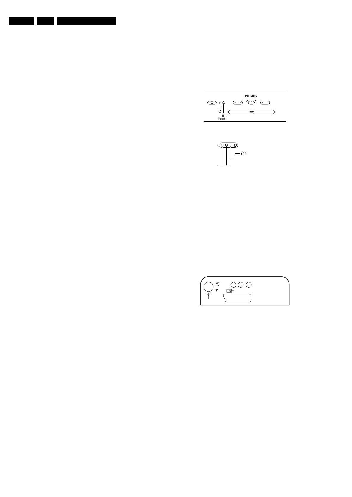
1.2 Connection/Control Facilities
1.2.1 TV Side Connections and Front Control
FRONT CONTROL
PHILIPS
- VOLUME + - PROGRAM +
IR
Receiver
SIDE I/O
3.5
VIDEO
Figure 1-1 Side connections and Front control
Cinch (Input)
1 -CVBS 1 Vpp / 75 Ω jq
2 -Audio - L 0.5 Vrms / 10 kΩ jq
3 -Audio - R 0.5 Vrms / 10 kΩ jq
Mini Jack: Headphone - Out
- Headphone 32 - 600 Ω / 10 mW rt
1.2.2 TV Rear Connections
REAR CONNECTIONS
AUDIO R
AUDIO L
EURO-AV
CL 36532059_001.eps
PCMA/RA/L
CL 26532120_002.eps
310703
251002
1.1.3 Miscellaneous
Audio Output (RMS) : 2 x 3 W
Mains Voltage : 150 - 240 V (± 10 %)
Mains Frequency : 50 (± 5 %)
Power Consumption : 50 W
Standby Power Consumption : < 3 W
Figure 1-2 Rear connections
Aerial - In
- IEC - type Coax, 75 Ω D
Cinch (Output)
1 -Audio - L 0.5 Vrms / 1 kΩ kq
2 -Audio - R 0.5 Vrms / 1 kΩ kq
3 -Digital Audio SPDIF kq
Page 3

Technical Specifications, Connections, and Chassis Overview
EN 3TDVD2.1E AA 1.
Euro AV
121
CL96532137_056.eps
Figure 1-3 SCART connector
1 -Audio - R 0.5 Vrms / 1 kOhm k
2 -Audio - R 0.5 Vrms / 10 kOhm j
3 -Audio - L 0.5 Vrms / 1 kOhm k
4 -Audio Ground H
5 -Blue Ground H
6 -Audio - L 0.5 Vrms / 10 kOhm j
7 -Blue 0.7 Vpp / 75 Ohm j
8 -CVBS-status 0 - 1.3 V: INT
4.5 - 7 V: EXT 16:9
9.5 - 12 V: EXT 4:3
9 -Green Ground H
10 -
11 - Green 0.7 Vpp / 75 Ohm j
12 -
13 - Red Ground H
14 - CVBS status Ground H
15 - Red 0.7 Vpp / 75 Ohm j
16 - RGB status 0 - 0.4 V: INT
1 - 3 V: EXT / 75 Ohm j
17 - CVBS Ground H
18 - RGB status Ground H
19 - CVBS-out 1 Vpp / 75 Ohm k
20 - CVBS-in 1 Vpp / 75 Ohm j
21 - Shielding Ground H
202
171199
Slave Interface Connector (CN7)
1-INTOR k
2-GND H
3 -VDATAIN k
4 -VDATAOUT k
5-VCLK k
6-VSTB k
External A/V Interface Connector(CN8)
1-POWER k
2-STOP k
3 - EJECT k
4-LED1 k
5 - NEXT k
6-BACK k
7 - PLAY k
8-LED2 k
9 - EXT_IF_! k
10 - EXT_IN_2 k
11 - Ground H
1.2.3 DVD Module Connections
DC Power Connector (CN1)
1 - Supply voltage + 12 V
2 -Ground GND H
3-Supply voltage + 3.3 V
4 - Ground (analogue) A-GND H
5 - Ground (digital) D-GND H
6 - Supply voltage + 5 V
7 - Power Control Active high
A/V and DAIC Output (CN6)
1 - R/R (PCM3) Rear Right Audio (Audio Data 3) k
2 - AGND Audio Ground H
3 - R/L (PCM2) Rear Left Audio (Audio Data 2) k
4 - CEN (PCM1) Centre Audio (Audio Data 1) k
5 - A-GND Audio Ground H
6 - S/W (PCM0) Sub Woofer (Audio Data 0) k
7 - F/R (SCK) Front Right Audio (System clock) k
8 - AGND Audio Ground H
9 - F/L (BCK) Front Left Audio (Audio bit clock) k
10 - MUTE (LRCK) Mute for Audio (Audio L/Rch clock) k
11 - SPDIF Digital Audio k
12 - D-GND Digital Ground H
13 - CVBS 1 Vpp / 75 Ohm k
14 - VGND Video Ground H
15 - Y 1 Vpp / 75 Ohm k
16 - VGND Video Ground H
17 - C 0.3 Vpp / 75 Ohm k
18 - VGND Video Ground H
19 - G(Y) 0.7 Vpp / 75 Ohm k
20 - B(Cb) 0.7 Vpp / 75 Ohm k
21 - R(Cr) 0.7 Vpp / 75 Ohm k
22 - VGND Video Ground H
23 - VID_S/W Video switching k
24 - TV_S/W TV switching k
25 - MODE1 SCL or TXD k
26 - MODE2 SDA or RXD k
Page 4
EN 4 TDVD2.1E AA1.
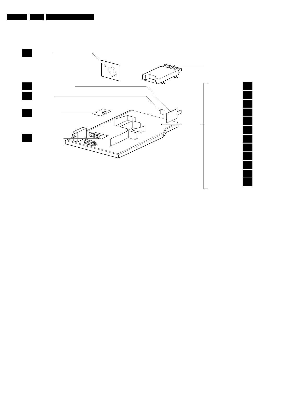
1.3 Chassis Overview
CRT PANEL
B
Technical Specifications, Connections, and Chassis Overview
DVD ENGINE
MAINS SWITCH PANEL
F
LED PANEL
C
SIDE AV PANEL
D
LINE OUT PANEL
E
Figure 1-4 PWB location
MAIN
CHASSIS
PANEL
TUNER
EEPROM
AUDIO AMPLIFIER
VERTICAL
VIDEO PROCESSOR
DVD AV
µ-CONTROLLER
DVD OUT
POWER SUPPLY
SCART
KEYBOARD
HORIZONTAL
CL 36532059_002.eps
A1
A2
A3
A4
A5
A6
A7
A8
A9
A10
A11
A12
040803
Page 5

Safety Instructions, Warnings, and Notes
2. Safety Instructions, Warnings, and Notes
EN 5TDVD2.1E AA 2.
Index of this chapter:
2.1 Safety Instructions
2.2 Maintenance Instructions
2.3 Warnings
2.4 Notes
2.1 Safety Instructions
Safety regulations require that during a repair:
• Due to the chassis concept, a part of the circuitry is 'hot'.
Therefore, connect the set to the mains via an isolation
transformer.
• Replace safety components, indicated by the symbol
only by components identical to the original ones. Any
other component substitution (other than original type) may
increase risk of fire or electrical shock hazard.
• Wear safety goggles when you replace the CRT.
Safety regulations require that after a repair, you must return
the set in its original condition. Pay, in particular, attention to
the following points:
• General repair instruction: as a strict precaution, we advise
you to re-solder the solder connections through which the
horizontal deflection current is flowing. In particular this is
valid for the:
1. Pins of the line output transformer (LOT).
2. Fly-back capacitor(s).
3. S-correction capacitor(s).
4. Line output transistor.
5. Pins of the connector with wires to the deflection coil.
6. Other components through which the deflection current
flows.
Note: This re-soldering is advised to prevent bad connections
due to metal fatigue in solder connections, and is therefore only
necessary for television sets more than two years old.
• Route the wire trees and EHT cable correctly and secure
them with the mounted cable clamps.
• Check the insulation of the mains cord for external
damage.
• Check the strain relief of the mains cord for proper function,
to prevent the cord from touching the CRT, hot
components, or heat sinks.
• Check the electrical DC resistance between the mains plug
and the secondary side (only for sets that have an isolated
power supply). Do this as follows:
1. Unplug the mains cord and connect a wire between the
two pins of the mains plug.
2. Turn on the main power switch (keep the mains cord
unplugged!).
3. Measure the resistance value between the pins of the
mains plug and the metal shielding of the tuner or the
aerial connection of the set. The reading should be
between 4.5 MΩ and 12 MΩ.
4. Switch the TV 'off' and remove the wire between the
two pins of the mains plug.
• Check the cabinet for defects, to prevent the possibility of
the customer touching any internal parts.
h,
Output Power : 20 mW (DVD+RW
writing)
: 0.8 mW (DVD
reading)
: 0.3 mW (VCD/CD
reading)
Beam divergence : 60 degree
Figure 2-1
Note: Use of controls or adjustments or performance of
procedure other than those specified herein, may result in
hazardous radiation exposure. Avoid direct exposure to beam.
2.2 Maintenance Instructions
We recommend a maintenance inspection carried out by
qualified service personnel. The interval depends on the usage
conditions:
• When a customer uses the set under normal
circumstances, for example in a living room, the
recommended interval is three to five years.
• When a customer uses the set in an environment with
higher dust, grease, or moisture levels, for example in a
kitchen, the recommended interval is one year.
• The maintenance inspection includes the following actions:
1. Perform the 'general repair instruction' noted above.
2. Clean the power supply and deflection circuitry on the
chassis.
3. Clean the picture tube panel and the neck of the picture
tube.
2.3 Warnings
2.3.1 General
• In order to prevent damage to ICs and transistors, avoid all
high voltage flashovers. In order to prevent damage to the
picture tube, use the method shown in Fig. 2-2, to
discharge the picture tube. Use a high voltage probe and a
multi-meter (position V
reading is 0 V (after approx. 30 s).
V
). Discharge until the meter
DC
2.1.1 Laser Safety
This unit employs a laser. Only qualified service personnel may
remove the cover, or attempt to service this device (due to
possible eye injury).
Laser Device Unit
Type : Semiconductor laser
GaAlAs
Wavelength : 650 nm (DVD)
: 780 nm (VCD/CD)
CL96532156_040.eps
140501
Figure 2-2 Discharge picture tube
• All ICs and many other semiconductors are susceptible to
electrostatic discharges (ESD, symbol w). Careless
handling during repair can reduce life drastically. Make
Page 6

EN 6 TDVD2.1E AA2.
sure that, during repair, you are connected with the same
potential as the mass of the set by a wristband with
resistance. Keep components and tools also at this
potential. Available ESD protection equipment:
– Complete kit ESD3 (small tablemat, wristband,
connection box, extension cable and ground cable)
4822 310 10671.
– Wristband tester 4822 344 13999.
• Together with the deflection unit and any multi-pole unit,
flat square picture tubes form an integrated unit. The
deflection and the multi-pole units are set optimally at the
factory. We do not recommend adjusting this unit during
repair.
• Be careful during measurements in the high voltage
section and on the picture tube.
• Never replace modules or other components while the unit
is 'on’.
• When you align the set, use plastic rather than metal tools.
This will prevent any short circuits and the danger of a
circuit becoming unstable.
2.3.2 Laser
• The use of optical instruments with this product, will
increase eye hazard.
• Only qualified service personnel may remove the cover or
attempt to service this device, due to possible eye injury.
• Repair handling should take place as much as possible
with a disc loaded inside the player.
• Text below is placed inside the unit, on the laser cover
shield:
Safety Instructions, Warnings, and Notes
CAUTION VISIBLE AND INVISIBLE LASER RADIATION WHEN OPEN AVOID EXPOSURE TO BEAM
ADVARSEL SYNLIG OG USYNLIG LASERSTRÅLING VED ÅBNING UNDGÅ UDSÆTTELSE FOR STRÅLING
ADVARSEL SYNLIG OG USYNLIG LASERSTRÅLING NÅR DEKSEL ÅPNES UNNGÅ EKSPONERING FOR STRÅLEN
VARNING SYNLIG OCH OSYNLIG LASERSTRÅLNING NÄR DENNA DEL ÄR ÖPPNAD BETRAKTA EJ STRÅLEN
VARO! AVATTAESSA OLET ALTTIINA NÄKYVÄLLE JA NÄKYMÄTTÖMÄLLE LASER SÄTEILYLLE. ÄLÄ KATSO SÄTEESEEN
VORSICHT SICHTBARE UND UNSICHTBARE LASERSTRAHLUNG WENN ABDECKUNG GEÖFFNET NICHT DEM STRAHL AUSSETSEN
DANGER VISIBLE AND INVISIBLE LASER RADIATION WHEN OPEN AVOID DIRECT EXPOSURE TO BEAM
ATTENTION RAYONNE MENT LASER VISIBLE ET INVISIBLE EN CAS D'OUVERTURE EXPOSITION DANGEREUSE AU FAISCEAU
!
Figure 2-3
2.4 Notes
• Measure the voltages and waveforms with regard to the
chassis (= tuner) ground (H), or hot ground (I), depending
on the tested area of circuitry.
• The voltages and waveforms shown in the diagrams are
indicative. Measure them in the Service Default Mode (see
chapter 5) with a colour bar signal and stereo sound (L: 3
kHz, R: 1 kHz unless stated otherwise) and picture carrier
at 475.25 MHz (PAL) or 61.25 MHz (NTSC, channel 3).
• Where necessary, measure the waveforms and voltages
with (D) and without (E) aerial signal. Measure the
voltages in the power supply section both in normal
operation (G) and in standby (F). These values are
indicated by means of the appropriate symbols.
• The picture tube panel has printed spark gaps. Each spark
gap is connected between an electrode of the picture tube
and the Aquadag coating.
• The semiconductors indicated in the circuit diagram and in
the parts lists, are interchangeable per position with the
semiconductors in the unit, irrespective of the type
indication on these semiconductors.
Page 7

3. Directions for Use
You can download this information from the following websites:
http://www.philips.com/support
http://www.p4c.philips.com
Directions for Use
EN 7TDVD2.1E AA 3.
Page 8

EN 8 TDVD2.1E AA3.
12
Mark
MENU
OK
”
P
564
879
0
¢
∫
ù
¤
ª
3
--
++
.
[
Zoom DVD Menu
Search
A-B
Repeat Clear
Subtitle
Fast
Skip
Ω™
Ë
›
ÓŸ
∏
Æ
∆
TV/DVD
Audio
-
Á
Ø
Ê
fl
3
The remote control keys
TV: Information Screen
To display / hide the programme
number,name (if there is one) sound
mode *, and the time remaining on
the timer.
DVD:Info. on playing (p.10)
DVD keys (p. 10,12)
TV: teletext keys (p.8)
Rewind and fast forward (p.10)
Stop, Eject (p. 10)
Cursor
These four keys navigate the menus.
Menu
To call or close menus
Selection of EXT sockets
Press several times to select EXT
and AV (p. 13).
* Only available on stereo versions
Standby
Lets you place the TV set in standby.
To turn on the TV, press
@
P
#
,
b
,
0 to 9
.
TV: Call teletext (p. 8)
DVD : disc menu (p. 10)
16:9 format
To select different screen formats.
Change track (p.10)
Play, pause (p. 10)
Volume
To adjust the sound level
Mute
Mute or bring back sound.
TV: Sound mode *
Changes
Stereo
and
Nicam
Stereo
transmissions into
Mono
or for bilingual transmissions to
choose between
Dual I
or
Dual II
.
DVD:choice of language
(p. 11)
Programme selection
To access the next or previous
programme. For certain programmes,
the title of the programme will be
displayed at the bottom of the screen.
Picture and sound settings
Accesses a series of picture and
sound settings.
The position PERSONAL corresponds
to the settings stored in the menus.
Numerical keys
Direct access to the programmes.
For a two digit programme, enter
the second digit before the dash
disappears.
Previous programme
To access the previously displayed
programme
Validation
TV / DVD mode
To switch between TV or DVD
mode
(p. 10)
.
The television has 6 keys located on the front
of the set.
The
;
key switches the TV set on and off.
The
fl
key opens and closes the DVD player.
The VOLUME - + (-
”
+) keys adjust the
sound.
The - + select the programmes.
To access the menus simultaneously press the
”
- and
”
+ keys.The P - + keys select a
setting and the
”
- + keys make adjustments.
To quit the menu displayed, press and keep
pressed the two keys
”
- and
”
+.
Note: when the
childlock
is active, the keys are
deactivated (see p. 7).
2
&
Positioning the television set
Place your TV on a solid, stable surface, leaving
a space of at least 5 cm around the appliance.
To avoid accidents,do not put anything on the
set such as a cloth or cover, a container full of
liquid (vase) or a heat source (lamp).The set
must not be exposed to water.
é
Connections
• Insert the aerial plug into the
:
socket at
the rear of the set.
If you are using an indoor aerial, reception may be
difficult in certain conditions.You can sometime improve
reception by rotating the aerial. If the reception
remains poor, you will need to use an external aerial.
• Insert the mains plug into a wall socket
(220-240 V / 50 Hz).
“
Remote control
Insert the two R6-type batteries (supplied)
making sure that they are the right way round.
Check that the mode selector is set to TV.
The batteries supplied with this appliance do not
contain mercury or nickel cadmium. If you have
access to a recycling facility, please do not discard
your used batteries (if in doubt, consult your dealer).
When the batteries are replaced, use the same type.
‘
Switching on
To switch on the set, press the on/off key.
A red indicator comes on and the screen
lights up. If the television remains in standby
mode, press P
#
on the remote control.
The indicator will flashe when you use the remote
control.
T
5 cm
5 cm
5 cm
Installing your television set
The keys on the TV set
Directions for Use
Page 9
Directions for Use
5
Manual store
DVD player menu
This menu is used to store the programmes
one at a time or to add a programme to the
existing list.
& Press the
H
key to display the
MAIN MENU
.
Select
INSTALLATION
with the cursor then the
manual store
menu
then press
u
.
é
System
: select
Europe
(automatic detection*)
or according to the versions
Western Europe
(BG standard),
Eastern Europe
(DK
standard),
United Kingdom
(I standard) or
France
(LL’ standard).
* Except for France (LL’standard), you must select
the choice
France
.
“
Search
: press
¬
.The search starts. Once a
programme is found, the scanning stops. Go to
the next step. If you know the frequency of the
required programme, enter its number directly
with the
0
to
9
keys.
If no picture is found, consult the possible solutions
(p. 14).
‘
Fine tuning
: if the reception is not satisfactory,
adjust using the
Ȭ
keys.
(
Programme:
enter the desired number with
the keys
Ȭ
or
0
to
9
.
§
Name:
use the
Ȭ
keys to move around
the name display area (5 characters) and the
îÏ
keys to select the characters.
When the name has been entered press the
È
key to exit.
è
Store
: press
¬
.The programme is stored.
! Repeat steps é to è for each programme to
be store.
ç To exit the menus press
H
several times.
Use this menu to set the preferences of the
integrated DVD player.
& Press the
H
key.The
MAIN MENU
is
displayed on screen.
é Use the
îÏ
key on the remote to select
DVD SETUP
then confirm with
u
.
The DVD menu appears and the TV set switches
to DVD mode. Use the
îÏ
keys to select a
setting and
u
to confirm, enter or leave
submenus.
“
TV aspect
: to select the required screen
format.
‘
Audio
: to select the preferred language of the
DVD film sound track.
If the preferred language is available on the disk it
will be selected by default. Otherwise the first
language of the disk will be activated.
(
Subtitle
: to select the preferred subtitle
language of the DVD films.
§ Disk Menu
: to define the preferred language of
the DVD disk menu.
è Parental
: to activate parental locking level from
1 (minimum) to 8 (maximum).The
off
position
deactivates the feature.
Some DVD disks have locking levels (1 to 8),
sometimes with replacement scenes. For example,
if you choose Level 4, all the scenes of level 4 (and
lower) will be played. Scenes with a higher level will
not be played or replaced with replacement
scenes. If the disk does not have any replacement
scene, it stops playing and you have to enter the
four figure Password.
!
Passworld:
to change password. First key in
your old password,then key your new
password. Confirm by keying it a second time.
if you have forgotten your password press
Ê
four
times.
ç Press
H
.
several times to exit the menus
MAIN MENU
PICTURE
SOUND
FEATURES
INSTALLATION
DVD
Manual Store
Program 01
Name -----
System EUROPE
Search 671 MHz
Fine Tune
Store
MENU PRINCIPAL
IMAGE
SOUND
AUTRES MENUS
INSTALLATION
DVD
DVD SETUP
TV aspect
Audio
Subtitle
Disc Menu
Parental
Password
4
Choice of language and country
Automatic search
This menu can change the display language of
the menus and the country
On the first start up the language
menu
appears
automatically. Go directly to step
“
.
& Press the
H
key.The
MAIN MENU
is
displayed on the screen.
é Use the
îÏ
keys on the remote to select
INSTALLATION
then confirm with
u
.
“
Language
:
use the
Ȭ
keys to choose
your language.
‘ Select
Country
(
Ï
) and
use the
Ȭ
keys
to choose your country (
GB
for Great Britain).
This setting is used for the search, automatic
sorting of the programmes and teletext display.
If your country does not appear in the list,
select the choice ”. . .”
( If you want to exit the menus press
H
several times.
This menu allows you to automatically search
for all the programmes.
& First perform the & à ‘ operations then:
é Select
Auto store
(
Ï
) and press
¬
to start
the automatic search of the programmes
available in your region.The search takes
several minutes. Finally the
Sort
menu appears
automatically.If the programmes found have
not been correctly numbered,use the
Sort
menu to renumber them (see below).
If no picture is found see Tips (p. 14).
“ If you want to exit the menus, press
H
several times.
Programme sort
This menu allow you to change the numbering
of programmes.
& Press the
H
key.The
MAIN MENU
is
displayed on the screen.
é Select the
INSTALLATION
menu with the
cursor then the
Sort
menu .
“ Select the programme you want to move with
the
îÏ
keys and press
¬
.
‘ Then use the
îÏ
keys to choose the new
number and confirm with
È
.
( Repeat steps “ and ‘ as many times as
required to move the programmes.
§ To exit the menus,press
H
several times.
MAIN MENU
PICTURE
SOUND
FEATURES
INSTALLATION
DVD
INSTALLATION
LANGUAGE ENGLISH
Country GB
Auto Store
Manual Store
Sort
MAIN MENU
PICTURE
SOUND
FEATURES
INSTALLATION
DVD
INSTALLATION
LANGUAGE ENGLISH
Country GB
Auto Store Store
Manual Store
Sort
MAIN MENU
PICTURE
SOUND
FEATURES
INSTALLATION
DVD
INSTALLATION
LANGUAGE ENGLISH
Country GB
Auto Store
Manual Store
Sortrt
EN 9TDVD2.1E AA 3.
Page 10
EN 10 TDVD2.1E AA3.
7
Timer function
TV lock
This menu lets you use the TV set as an alarm
clock.
& Press the
H
key.
é With the cursor select the
FEATURES
menu
then
Timer
:
“
Sleep:
to select an automatic standby period.
‘
Time:
enter the current time.
Note
: each time the TV set is turned on, the time will
automatically be updated from the teletext on
programme 1. If this programme does not have
teletext, the update will not take place.
(
Start Time
: enter the start time.
§
Stop Time:
enter the stop time.
è
Programme No.:
enter the number of the
desired programme for the wake-up alarm.
!
Activate
: you can set:
•
Once
for a single alarm,
•
Daily
for each day,
•
Stop
to cancel.
ç Press
b
to put the TV set in standby.It will
automatically come on at the time
programmed. If you leave the TV set on, it will
just change programmes at the time entered
(and go into standby mode at the
Stop Time
).
This menu lets you block use of the TV set by
locking the keys.
& Press
H
.
é With the cursor select the
FEATURES
then
Child Lock
:
“ You must enter your secret access code.
The first time, key the code 0711 twice.
The menu is displayed.
‘ Switch
Child Lock
to
ON
.
( Switch the TV set off and hide the remote.
The TV set cannot be used (it can only be
switched on with the remote).
§ To cancel switch
Child Lock
to
OFF
.
è To change the code select
New Code
and
enter a new 4 figure code. Confirm by
entering a second time.
If you have forgotten your secret code, enter the
universal code 0711 twice.
! Press
H
several times to exit the menus
MAIN MENU
PICTURE
SOUND
FEATURES
INSTALLATION
DVD
Timer
Sleep OFF
Time -- : --
Start Time -- : --
Stop Time -- : --
Pr Nr 00
Activate OFF
MAIN MENU
PICTURE
SOUND
FEATURES
INSTALLATION
DVD
FEATURES
Timer
Childlock
6
Picture settings
Sound adjustments
(only available in stereo versions)
& Press
H
, select
PICTURE
and press
¬
.The
PICTURE
menu appears:
é Use the
îÏ
keys to select a setting and
Ȭ
keys to adjust.
“ Once the adjustments have been made select
Store
and press
¬
to store them.
‘ Press
H
several times to exit the menus.
Description of the adjustmensts:
•
Brightness:
this changes the picture brilliance.
•
Colour
: this changes the intensity of the
colour.
•
Contrast
: this changes the difference
between the light and dark tones.
•
Sharpness
: this changes the picture
definition
•
Colour Temp.
: this changes the colour
rendering:
Cold
(bluer),
Normal
(balanced) or
Warm
(redder).
•
NR
(Noise Reduction): reduces picture noise
(snow), in the case of difficult reception.
•
Contrast+
: automatically adjusts contrast of
the picture by making the darkest part of the
picture permanently black.
•
Store
: to store the picture adjustments.
& Press
H
, select
SOUND
(
Ï
) and press
¬
.
The
SOUND
sound menu is displayed:
é Use the
îÏ
keys to select a setting and
the
Ȭ
keys to adjust.
“ Once the adjustments have been made select
Store
and press
¬
to store them.
‘ To quit the menus press
H
several times.
Description of the settings:
•
Treble
: this alters the high frequency sounds.
•
Bass
: this alters the low frequency sounds.
•
Balance
: to balance the sound on the left
and right speakers.
•
Delta Volume
: this is used to compensate for
any volume discrepancies between the
different programmes or EXT sockets.
This setting is operational for programmes
0 to 40 and the EXT sockets.
•
AVL
(Automatic Volume Leveler): automatic
volume control which limits increases in sound,
especially on programme change or advertising
slots.
•
Store
: this is used to store sound settings.
MAIN MENU
PICTURE
SOUND
FEATURES
INSTALLATION
DVD
PICTURE
Brightness ---I-------
Colour
Contrast
Sharpness
Colour Temp.
NR Normal
Contrast+ OFF
Store ON
MAIN MENU
PICTURE
SOUND
FEATURES
INSTALLATION
DVD
SOUND
Treble ---I-------
Bass ------I----
Balance -----I-----
Delta volume ---I-------
AVL OFF
Store
Directions for Use
Page 11
Directions for Use
9
Using the built-in DVD player
Inserting a disc
The built-in DVD player allows you to play DVD video discs, picture CDs (jpeg format) and audio
CDs (including finalised CD-Rs, CD-RWs MP3 CDs).The discs can be recognised by their logo on
the packaging.
Note:
Generally, DVD films are not placed on the market at the same time in the various regions of the world.
Accordingly, DVD players are provided with geographical zone codes. If you insert a disc which has a regional
code that is different from that of your reader, you will see a message displayed on the screen.
The disc cannot be played and you will have to remove it.
&
Opening the drawer
Press the
fl
key located on the front of the TV
set.
é
Inserting the disc
Place the disc in the drawer, with the label
facing upwards. Makes sure that it is positioned
correctly in the recess.
“
Closing the drawer
Gently push the drawer or press the
fl
button
to close.The disk will begin to play.
‘
Automatic play
When the drawer is closed the TV set switches
to DVD mode then the content of the disk is
displayed.
PICTURE
8
Teletext
Press : You will obtain:
Teletext is an information system broadcast by certain channels which can be consulted like a
newspaper. It also offers access to subtitles for viewers with hearing problems or who are not familiar
with the transmission language (cable networks, satellite channels, etc.).
Teletext call
Selecting a
page
To call up or exit from teletext.
The summary appears
with a list of items that can be accessed. Each item has a
corresponding 3 digit page number.
If the channel selected does not broadcast teletext, the
indication 100 will be displayed and the screen will remain
blank (in this case, exit teletext and select another channel).
Enter the number of the page required using the
0
to
9
or
@ P #
keys. Example: page 120,enter
120
.
The number is displayed top left,the counter turns and
then the page is displayed.Repeat this operation to view
another page.
If the counter continues to search, this means that the page is
not transmitted. Select another number.
Direct
access to
the items
Coloured areas are displayed at the bottom of the screen.
The 4 coloured keys are used to access the items or
corresponding pages.
The coloured areas flash when the item or the page is not yet
available.
Contents
This returns you to the contents page (usually page 100).
Enlarge a
page
Stop sub-
page
acquisition
This allows you to display the top or bottom part of the
page and then return to normal size.
Certain pages contain sub-pages which are automatically
displayed successively.This key is used to stop or resume
sub-page acquisition.The indication STOP appears top left.
Hidden
information
Overlaying
text on the
TV picture
Temporary
suspension
of display
To display or hide the concealed information (games
solutions).
To activate or deactivate screen overlay.
This suspends or restarts teletext display.The televised
programme reappears.This saves waiting when page
searches are long.
EN 11TDVD2.1E AA 3.
¤
¤Ω
™
Ë
†
Clear
›
Repeat
A-BSubtile
ÓŸ
Æ
∫
∆
¢
Fast Skip
fl
Ê
DVD Menu
.
Mark Zoom
Search
0 9
OK
MENU
+
P
-
+ +
P
[
”
TV/DVD
- -
Audio
ª
-
ù
Ë
›
Á
0
Ø
3
564
879
12
Ó
Ÿ
Ω
™
Page 12
EN 12 TDVD2.1E AA3.
11
Playing an audio CD
Play
Once the disk has been inserted
,
play begins automatically.The current
track and time are displayed on the screen.
Changing tracks
Use the
¢ ∫
keys to change tracks or the
09
keys to select
the track of your choice.
Note: this function is not available with MP3 audio CDs.
Fast forward and rewind
Press
<<
or
>>
to fast forward or rewind
x2, x4,x8, x16 or x32
.
Press
Æ
to return to normal speed.
Pause / stop / eject
Press
∆
to pause and
Æ
to resume play.
Press
Ê
to stop and again to
eject
Direct access by time
Press
d
. Use the
09
keys to enter the exact time from which you
want to restart play.
Playing an MP3 audio CD
MP3 audio CDs allow you store several albums on a single disk.
A navigation menu is displayed on the screen with the list of the
various albums available Use the
îÏ
keys to make your selection
and the
u
keys to confirm. Repeat the operation to select the
desired track and start play.
The access track appears at the top of the
list.
The
È
key allows you to back up the hierarchy.
Reading an image CD
Reading and navigation
Once the disk has been inserted
,
a navigation menu appears on screen.
The list of folders and images is displayed on the left and a preview on the
right. Use the cursor
îÏȬ
to select the desired image and
press
u
to display it full screen.The images on the disk follow
automatically in order.To return to the navigation menu press
c
.
Preview
While reading the disk press the
Ê
key to display the preview menu.
Use the cursor
îÏȬ
to select the desired image and press
u
to display it in full screen.
Moving to another image
Use the
¢ ∫
keys to move to the next or previous image.
Rotating the image
Use the
Ȭ
keys to change the orientation of the image and the
îÏ
keys to reverse it.
Enlarging/reducing the image
Press the
Zoom
key several times to display the image in 2, 3 or 4
times scale. Use the
Ȭ îÏ
keys to move the enlarged image.
Mark Zoom
DVD Menu
A-BSubtile
Fast Skip
Repeat
MENU
P
¤Ω
ÓŸ
--
++
.
[
”
Clear
Search
™
›
12
Audio
TV/DVD
564
879
0
ù
Á
3
ª
-
Ø
†
∆
Æ
∫
¢
Ë
OK
Ê
fl
∫
∫
001/003
Î
ï
\
Holidays
Paris
Jennifer
10
Playing a DVD or a video CD
Choice of TV or DVD mode
Press the
TV/DVD
key on the remote to switch the TV set between
TV and DVD mode.
Play
Once the disk has been inserted, play begins automatically.On some
disks you may be invited to select a heading in a menu.Use the
09
or
îÏ È¬
keys as appropriate then press
u
.
Stop and ejection of the disk.
Press the
Ê
key once to stop play and a second time to eject the disk.
Resume play
When you interrupt playing a disk (going to TV mode or pressing
Ê
),
playing starts at the exact point where you have stopped it.
The resume function applies equally to the last 4 disks played.
Fast forward and rewind
Press the
<<
or
>>
key while playing to fast forward or rewind at x2,
x4, x8,x16 or x32. Speed. Press
Æ
to return to normal speed.
Stop on picture
Press
∆
to stop the picture. Press
Æ
again to resume play.
Next/previous chapter
DVD disks are split into different chapters to permit direct access to
certain scenes. Use the
¢ ∫
key to access the next or previous
chapter.
DVD disk menu
Press the
c
key.The DVD menu appears. Its contents will depend on
the DVD. It allows you to access different sections, such as choice of
language, direct access to certain scenes,special production notes,
trailers, etc.use the
Ȭ îÏ
keys to select and
u
confirm.
Langage selection
Press the
e
key to select the different languages available on the
disk.A menu bar appears at the top of the screen, this will disappear
after a few seconds.
Subtitling language
Press the
y
key to choose your subtitling language (choose
off
to
deactivate it).
Enlarging the picture
Press the
Zoom
key several times to enlarge the picture x2,x3 or x4.
Use the
Ȭ îÏ
keys to move the enlarged picture.
Information on playing
Press the
d
key. An information menu appears and in its upper part
the preview of the play in progress. Use the
îÏȬ
keys to go
through the different settings and access the submenus.
Use the
u
key to confirm and
d
to quit.
Menu
Title 01/03
Chapter 02/38
Audio English
Subtile English
Æ
Directions for Use
DVD Menu
.
Mark Zoom
Search
Æ
∫
¤
Clear
Ω
Repeat
A-BSubtile
™
Ë
OK
†
∆
›
Ó
Ÿ
¢
Fast Skip
fl
Ê
MENU
P
TV/DVD
ª
[
-
--
++
ù
Audio
”
3
564
12
Á
0
879
Ø
Page 13
Directions for Use
13
Connecting peripheral equipment
Carry out the connections shown opposite, using a good
quality euroconnector cable.
If your video recorder does not have a euroconnector socket, the only
connection possible is via the aerial cable.You will therefore need to
tune in your video recorder's test signal and assign it programme
number 0 (refer to manual store, p. 5).
To reproduce the video recorder picture,press
0
.
Video recorder with decoder
Connect the decoder to the second euroconnector socket of
the video recorder.You will then be able to record scrambled
transmissions.
Video recorder
Satellite receiver, decoder, games, etc.
Make the connections as shown opposite.
To connect a Hi-fi unit, use an audio connecting table and
connect:
- the ”L” and ”R” outputs of theTV set to an ”AUDIO IN” ”L”
and ”R” of the Hi-fi unit.
- The ”PCM” output of theTV set to a ”DIG IN” input of the
amplifier (amplifier with digital coaxial input).
Other equipment
Amplifier
VCR
564
879
0
Á
Ø
To select connected equipment
Press the
n
key to select EXT and AV for the side connections.
Most equipment (decoder, video recorder) carries out the switching itself.
Make the connections as shown opposite.
Headphones
When headphones are connected, the sound on the TV set
will be cut.The
@”#
keys are used to adjust the volume
level.
The headphone impedance must be between 32 and 600 Ohms.
Side connections
12
Marking and repeating play
The following functions let you program the player to repeat or to
repeat scenes or favourite parts of a disk.
Repeat play
Press the
Repeat
key several times to repeat the title,chapter or the
whole disk.
Repeat play between two points A -B
Press the
A-B
once to tag the starting point
A
of the repetition.
Press a second time to tag the point
B
. Play will repeat indefinitely
between the two points
A
and
B
.To cancel the repeat, press the
A-B
key again.
This function is not available with picture CDs.
Marking play
You can mark up to 12 points on the disk being played.These marks let
you return at any time to the scenes or parts that you have marked.
This function is not available with picture CDs.
& Press the
Mark
key to display or hide the Marking menu.
é Press the
u
key for each mark you want to make.The number of the
mark, the title,the chapter and the time of the marked point are
displayed.
“ Use the
îÏȬ
keys to navigate in the marking menu and press
u
to display the marked scene.
to cancel a tag press
Clear
key.
Glossary
RGB Signals:
These are 3 Red, Green and Blue video signals which directly drive
the red, green and blue emitters in the cathode ray tube. Using these
signals provides better picture quality.
NICAM sound:
Process by which digital sound can be transmitted.
System:
Television pictures are not broadcast in the same way in all countries.
There are different standards:BG, DK, I, and L L’.The SYSTEM setting
(p. 6) is used to select these different standards.This is not to be
confused with PAL or SECAM colour coding.Pal is used in most
countries in Europe, Secam in France,Russia and most African
countries.The United States and Japan use a different system called
NTSC.
16:9:
Refers to the ration between the length and height of the screen.
Wide screen televisions have a ration of 16/9,conventional screen TV
sets have a ration of 4/3.
01
Track: 02 Time 00:08
02
EN 13TDVD2.1E AA 3.
∫
¤Ω
†
Clear
DVD Menu
.
›
¢
Repeat
A-BSubtile
Ó
™
Mark Zoom
Fast Skip
Ÿ
Ë
Search
Page 14
EN 14 TDVD2.1E AA3.
Directions for Use
Personal Notes:
The proximity of mountains or high buildings may be responsible for ghost
pictures, echoing or shadows. In this case, try manually adjusting your
picture: see Fine Tuning (p.5) or modify the orientation of the outside
aerial.
Does your antenna enable you to receive broadcasts in this frequency range
(UHF or VHF band)?
menu to ON. (p. 6).
In the event of difficult reception (snowy picture) switch the NR on the
Picture
Have you connected the aerial socket properly?
Have you chosen the right system? (p.5). Poorly connected euroconnector
cables or aerial sockets are often the cause of picture or sound problems
(sometimes the connectors can become half disconnected if the TV set is
moved or turned). Check all connections.
To play a video cassette,check that it has been recorded under the same
standard (PAL,SECAM, NTSC) which can be replayed by the video
recorder.
Check that the mode selector on the side of the remote control is set to
TV.
If on certain channels you receive a picture but no sound,this means that
you do not have the correct TV system. Modify the System setting (p. 5).
Are certain characters not displayed correctly? Check that the Country
setting has been positioned correctly (p.4).
Check that the disc does not have any fingerprints on it.Clean it with a soft
cloth, wiping from the centre to the edge.
The TV set does not react to the remote control;the indicator on the set
no longer flashes when you use the remote control? Replace the batteries.
When you switch the TV set on it remains in standby mode and the
indication Locked is displayed when you use the keys on the TV set?
The Child Lock function is switched On (p. 7).
If the set receives no signal for 15 mins, it automatically goes into standby
Only use a clean, soft and lint-free cloth to clean the screen and the casing
of your set. Do not use alcohol-based or solvent-based products.
If your TV set breaks down,never attempt to repair it yourself:contact your
mode.
dealer's after-sales service.
To save power, your set is fitted with components that give it a very low power
consumption when in standby mode (less than 3 W).
Tips
Poor reception
Still no results?
Peripheral
equipment gives a
black and white
picture
The remote control
no longer works.
No sound
Teletext
Does the DVD
player no longer
No picture
work?
Standby
Remote control
Cleaning the set
14
Page 15

4. Mechanical Instructions
Mechanical Instructions
EN 15TDVD2.1E AA 4.
Index of this chapter:
4.1 Rear Cover Removal
4.2 Service Position Main Panel
4.3 DVD Module Removal
4.4 Side I/O Panel Removal
4.5 Rear I/O Panel Removal
4.6 Rear Cover Mounting
Note: Figures can deviate slightly from the actual situation.
4.1 Rear Cover Removal
1. Remove all fixation screws (4x) of the rear cover.
2. Pull the rear cover a little backwards.
3. Disconnect the Rear I/O panel
4. Now pull the rear cover backwards to remove it.
4.2 Service Position Main Panel
1. Disconnect all cables of the DVD module
2. Remove the main panel, by pushing the two centre clips
outward [1]. At the same time, pull the panel away from the
CRT [2].
3. Turn the panel 90 degrees clockwise [3].
4. Flip the panel 90 degrees [4], with the components towards
the CRT.
4.3 DVD Module Removal
Remove the complete DVD module after unscrewing the four
fixation screws [1].
CL 26532120_026.eps
311002
Figure 4-2 Disassemble DVD module
4.4 Side I/O Panel Removal
A
Remove the side I/O panel after unscrewing the screws (2x) at
the bottom of the set.
1
1
3
2
B
4
4.5 Rear I/O Panel Removal
Remove the rear I/O panel after unscrewing the two screws
from the inside of the rear cover.
4.6 Rear Cover Mounting
To reassemble the set, perform all described processes in
reverse order.
Be sure that, before the rear cover is mounted:
• The mains cord is mounted correctly in its guiding bracket.
• All wires/cables are returned in their original position.
Figure 4-1 Service position main panel
CL 26532120_027.eps
311002
Page 16

EN 16 TDVD2.1E AA5.
Service Modes, Error Codes, and Fault Finding
5. Service Modes, Error Codes, and Fault Finding
Index of this chapter:
5.1 Service Modes
5.1 Service Modes
The Service Mode is a combination of the TV Service Mode
and the DVD Service Mode. You can enter the DVD Service
Mode via the TV Service Mode. The Service Mode offers
features, which the service technician can use to repair a set.
Any feature change, made via the Service Menu, will respond
at the same time (for example; if Hotel Mode is enabled, the
volume cannot be increased above max. volume displayed at
the Service Menu).
The Dealer Mode is a special DVD mode, to provide an auto
replay function for commercial purposes.
All displayed text strings in the Service Modes are in English.
5.1.1 TV Service Mode
Purpose
• To perform alignments (e.g. colour adjustment and
geometry alignments)
• To change option settings
• Hotel Mode operations
• DVD Service menu
Specifications
All service unfriendly modes (if present) are disabled, like:
• Auto switch 'off' (when there is no 'ident' signal)
• Timer switch to a channel
• Automatic user menu time-out
• The NVM is unprotected
• AV functions are not working
How to enter the Service Mode
Screen menu's must be 'off', when you enter the Service Mode.
Use a standard customer RC-transmitter and key in the code
062596 directly followed by the MENU button.
The following screen is visible when you enter the Service
Mode:
LLLLLLLPAB#- XX
OPT I ONS
GEOMET RY
G2ADJ
VIDEO
TUNE/ IF
DVD
Ho t e l M OFF
V o l u m e ------ --- --- --- --- --- --- --- --- --- --- --- --- ---
Figure 5-1 TV Service Mode menu
1. LLLLLLL. This is the used IC type.
2. PAB#-XX. This is the software identification.
– P = Philips.
– A = the region (W = West Europe, E = East Europe).
– B = sound specification (M = Mono, S = Stereo).
– # = number of TXT pages.
– XX = the software version number (the first X is the
main software version number and the second X is the
sub software version number).
3. PROGRAM. .......
4. OPTIONS. Three codes possible.
5. GEOMETRY. To align the geometry (see chapter 8.x for a
detailed description).
6. G2A. To align the G2 (see chapter 8.x for a detailed
description).
7. VIDEO. To adjust RGB, R_cut-off and G_cut-off.
CL 26532120_018.eps
311002
8. TUNE/IF. To align the tuner.
9. DVD. To enter the DVD Service Mode.
10. HOTEL M. To switch the Hotel mode 'on/off'.
11. VOLUME. To adjust the volume when Hotel mode is 'off'.
How to navigate
• Select menu items with the CURSOR UP/DOWN keys.
• With the CURSOR LEFT/RIGHT keys, it is possible to
change the value of the first (Program) and last two menu
items (Hotel mode and Volume).
• With the CURSOR RIGHT and OK keys, activate the
selected menu item.
• When you press the MENU key in a sub menu, you will
return to the previous menu.
• When you press the MENU key in the Service Mode menu,
you will return to the Main menu.
How to exit
• With the STANDBY command, the set switches to
Standby.
• With the MENU key, the set returns to the Main menu.
Switching the set 'off' and 'on' with the mains switch, brings the
set into normal operation again.
All changes in the Service Mode are stored immediately.
5.1.2 Dealer Mode
Purpose
• To provide an auto replay function (commercial purpose).
• To ignore some features.
Pre-conditions to start the Dealer Mode are:
• Put the set in DVD Mode (not necessary but is better).
• Switch Teletext 'off' (if set is in TV Mode).
• Switch Childlock 'off'.
• No screen Menu's.
• A disc is present in the tray.
• Close disc tray.
• Switch the DVD in STOP condition.
Specifications
• The information line displays the current mode.
• The set starts to play the disc.
• The Disc Menu passes automatically.
• At the end of the disc, the set replays the disc from chapter
1 onwards.
In Dealer Mode, some restrictions and rules are defined:
• While the Dealer Mode is active, you cannot use the
STANDBY key (RC reception is blocked), so it is not
possible to go to standby. The only way to switch off the set
is to switch the Mains Power 'off'.
• When the mains Power is switched 'on', the set will go out
of standby (DVD Mode) automatically.
How to enter the Dealer Mode
Use a standard RC-transmitter and key in the code 9999
directly followed by the MENU button.
The set will now switch to Dealer Mode. The current mode is
written to the NVM.
The set switches to the DVD mode and informs the DVD about
the current mode
Page 17

Service Modes, Error Codes, and Fault Finding
Dea l e r Mode ON
EN 17TDVD2.1E AA 5.
How to exit
Use a standard RC-transmitter and key in the code 9999
directly followed by the MENU button.
The Play mode is stopped, the Dealer mode is deactivated, and
the TV menu returns
Figure 5-2 Dealer Mode menu
D101-04
C101-04
C106, T101
R107, R105
open and
short circuit
R106
R111, D107
CL 26532120_019.eps
311002
YES
NO
YES
YES
Fuse
F1
Defective
NO
Voltage at
drain of
T101
Voltage at
I101 pin 11
< 1V
NO
start-up
voltage (6)
pin 14
< 8V
Switched mode
Power Supply defective,
+112V is missing or
level is wrong
YES
T101
V101, R103
YES
NO
NO
start-up
voltage
varies ca.
8V
NO
I101
Measure
+112V
adjustable with
V101
YES
Control range of
switched-mode
Power Supply
CL 36532059_007.eps
010803
Figure 5-3 Fault tracing diagram power supply
Page 18

EN 18 TDVD2.1E AA5.
Personal Notes:
Service Modes, Error Codes, and Fault Finding
E_06532_012.eps
131004
Page 19

Block Diagrams, Test Point Overviews, and Waveforms
6. Block Diagrams, Test Point Overviews, and Waveforms
Block Diagram
19TDVD2.1E AA 6.
CL 36532059_003.eps
010803
Page 20

Block Diagrams, Test Point Overviews, and Waveforms
I2C Bus Interconnection Diagram
A1
A2
A4
20TDVD2.1E AA 6.
A7
+5V
TUNER
SDA
5
SCL
4
Chassis Diagram
R614
R613
SDA
SCL
R333
R013
R334
52
51
VIDEO
PROC.
SDA
SCL
R048
R049
65
EEPROM
SDA
SCL
20 19
u-CONTROLLER
R012
CL 36532059_005.eps
SDA
SCL
010803
CL 36532059_006.eps
040803
Page 21

Block Diagrams, Test Point Overviews, and Waveforms
Supply Voltage Diagram
21TDVD2.1E AA 6.
CL 36532059_004.eps
010803
Page 22

Circuit Diagrams and PWB Layouts
22TDVD2.1E AA 7.
7. Circuit Diagrams and PWB Layouts
Main Panel: Tuner
A1
Main Panel: Audio Amplifier
A3
Main Panel: EEPROM
A2
CL 36532059_010.eps
010803
CL 36532059_009.eps
010803
CL 36532059_011.eps
010803
Page 23

Circuit Diagrams and PWB Layouts
23TDVD2.1E AA 7.
Main Panel: Vertical
A4
Main Panel: Video Processor
A5
CL 36532059_012.eps
010803
CL 36532059_013.eps
010803
Page 24

Circuit Diagrams and PWB Layouts
24TDVD2.1E AA 7.
Main Panel: DVD AV
A6
DVD AV
Main Panel: DVD OUT
A8
DVD OUT
CL 36532059_014.eps
040803
Main Panel: SCART
A10
Main Panel: Keyboard
A11
CL 36532059_016.eps
010803
CL 36532059_018.eps
010803
CL 36532059_019.eps
010803
Page 25

Circuit Diagrams and PWB Layouts
25TDVD2.1E AA 7.
Main Panel: u-Controller
A7
Personal Notes:
CL 36532059_015.eps
010803
Page 26

Circuit Diagrams and PWB Layouts
Main Panel: Power Supply
26TDVD2.1E AA 7.
A9
POWER SUPPLY
RESERVED
I104
T111
R161
Z102
R162
C152
R163
C153
R164
R159
R165
V102
D118
C116
D119
D121
F_14170_001.eps
290905
Page 27

Main Panel: Horizontal
A12
Circuit Diagrams and PWB Layouts
27TDVD2.1E AA 7.
EKRANAS CRT
L402 = 150uH
L403 = 100uH
L402 = 150uH
R409 = 68R FUS
C404 = 8nF1, 6KV
TOSHIBA CRT
L402 = 150uH
L403 = 100uH
L402 = 150uH
R409 = 68R FUS
F_14170_002.eps
290905
Page 28

Circuit Diagrams and PWB Layouts
Layout Main Panel (Top Side)
28TDVD2.1E AA 7.
CL 36532059_042.eps
040803
Page 29

Circuit Diagrams and PWB Layouts
Layout Main Panel (Bottom Side)
29TDVD2.1E AA 7.
CL 36532059_043.eps
040803
Page 30

Circuit Diagrams and PWB Layouts
30TDVD2.1E AA 7.
Picture Tube Panel
PICTURE TUBE PANEL
B
Layout Picture Tube Panel (Top Side)
CL 36532059_021.eps
010803
CL 36532059_023.eps
010803
Layout Picture Tube Panel (Bottom Side)
CL 36532059_022.eps
010803
Page 31

Circuit Diagrams and PWB Layouts
31TDVD2.1E AA 7.
LED Panel
LED
C
Layout LED Panel
CL 36532059_024.eps
010803
Front AV Panel
D
CL 36532059_025.eps
010803
Layout Front AV Panel (Top Side)
CL 36532059_027.eps
Layout Front AV Panel (Bottom Side)
010803
CL 36532059_026.eps
010803
CL 36532059_028.eps
010803
Page 32

Circuit Diagrams and PWB Layouts
32TDVD2.1E AA 7.
Line Out Panel
E
Layout Line Out Panel
CL 36532059_029.eps
010803
Mains Switch Panel
F
CL 36532059_030.eps
010803
Layout Mains Switch Panel
CL 36532059_031.eps
010803
CL 36532059_032.eps
010803
Page 33

8. Alignments
Alignments
EN 33TDVD2.1E AA 8.
Index of this chapter:
8.1 Hardware Alignments
8.2 Software Alignments/Settings
8.1 Hardware Alignments
8.1.1 System Voltage Adjustment
• Switch the TV in AV mode by pressing the AV button on the
remote control unit (minimum beam current condition).
• Adjust the V101 potentiometer until you measure 112 Vdc
on the cathode of diode D108.
8.2 Software Alignments/Settings
Enter the TV Service Mode (see chapter 5). The Service Mode
menu will now appear on the screen.
LLLLLLLPAB#- XX
OPT I ONS
GEOMET RY
G2ADJ
VIDEO
TUNE/ IF
DVD
Ho t e l M OFF
V o l u m e --- --- --- --- --- --- --- --- --- --- --- --- --- --- ---
Figure 8-1 Service mode menu
Select one of the following alignments:
1. OPTIONS.
2. GEOMETRY.
3. G2ADJ.
4. VIDEO.
5. TUNE/IF.
8.2.1 Options
Options are used to control the presence/absence of certain
features and hardware.
An Option byte represents a number of different options. All
options are controlled via three option bytes.
OPT I ONS
O1 11111111
O2 01010000
O3 11100111
Figure 8-2 Option menu
How to change an Option byte
Select the option byte (01, 02 or 03) with the CURSOR UP/
DOWN keys.
Use a digit key (0 to 7) to change the relevant option bit. The bit
values will change from 0 to 1 and from 1 to 0 on each pressing
of the relevant digit key.
CL 26532120_018.eps
CL 26532120_020.eps
311002
311002
Option bit definition
Option byte 1 (01): System configuration
b0
1: Welcome bit enabled
0: Welcome bit disabled
b1
1: PAL I enabled (/05 selected)
0: PAL I disabled (/01 and /58 selected)
b2
1: SECAM L enabled
0: SECAM L disabled
b3
1: not available
0: not available
b4
1: Standby after power 'on'
0: Last state after power 'on'
b5
0: not available
1: not available
b6
0: not available
1: not available
b7
0: not available
1: not available
Option byte 2 (02): Video configuration
b0
1: QSS application
0: Intercarrier application
b1
1: Blue Screen enabled
0: Blue Screen disabled
b2
1: OSD Contrast Control enabled
0: OSD Contrast Control disabled
b3
1: APR ON (Auto Peak Regulation 'on')
0: APR OFF (Auto Peak Regulation 'off')
b4
1: Blue Screen disable
0: Enable
b5
1: OSD Contrast Control enable
0: Disable
b7-b6-b5-b4
0000: APR 50 IRE
0001: APR 53.33 IRE
0010: APR 56.66 IRE
0011: APR 60 IRE
0100: APR 63.33
0101: APR 66.66
0110: APR 70
0111: APR 73.33
1000: APR 76.66
1001: APR 80
1010: APR 83.33
1011: APR 86.66
1100: APR 90
1101: APR 93.33
1110: APR 96.66
1111: APR 100
Option byte 3 (03): Feature configuration
b0
1: DVD available
0: DVD not available
Page 34

EN 34 TDVD2.1E AA8.
Alignments
b1
1: 2248E (microprocessor)
0: 2248C (microprocessor)
b2
1: One Crystal applied (4.43 MHz)
0: Two crystals applied (for NTSC playback)
b3
1: CVBS output 2.3 V
0: CVBS output 2.0 V
b4
1: not available
0: not available
b5
1: not available
0: not available
b7-b6
00: ALPS tuner
01: UV1316
10: Thomson/Orega CTFF5510
Table 8-1 Opion Codes
Option 1 Option 2 Option 3
14PT6807/01 1110 1101 1101 1001 1011 1011
14PT6807/01 1110 1111 1101 1001 1011 1011
14PT6807/01 1110 1001 1101 1000 1011 1011
8.2.2 Geometry
The Geometry Alignments menu contains several items to
align the set, in order to obtain a correct picture geometry.
8.2.3 G2 Adjust menu
In this menu we will see a comparative display according to the
preset. To adjust the G2, turn the G2 potentiometer on the LOT
until you reach the ':' sign. If the colon is highlighted,
adjustment is achieved ('<' means you have to decrease and '>'
means you have to increase).
G2A
>:<
Figure 8-4 G2 adjustment menu
8.2.4 Video
4
Figure 8-5 Video alignment menu
CL 36532059_038.eps
CL 36532059_039.eps
010803
010803
VS4/350h0
CL 36532059_037.eps
010803
Figure 8-3 Geometry alignment menu
How to align
Enter the Service Mode and select the GEOMETRY settings.
Standard geometry adjustments are carried out by VS, VP and
HP settings.
VS 16/9 50h setting has to be carried out until 3 cm distance
between upper and lower parts of the screen.
Same adjustments are valid for 60h 16/9 and 4/3.
• V.S4/3 50h Vertical size property of picture at 50 Hz 4/3
aspect ratio broadcast (default value 10).
• V.S16/9 50h Vertical size property of picture at 50 Hz 16/9
aspect ratio broadcast (default value 15).
• V.SEXP 50h Vertical size property of picture at 50 Hz 16/9
expand aspect ratio broadcast (default value 0).
• V.S4/3 60h Vertical size property of picture at 60 Hz 4/3
aspect ratio broadcast (default value 7).
• V.S16/9 60h Vertical size property of picture at 60 Hz 16/9
aspect ratio broadcast (default value 11).
• V.SEXP 60h Vertical size property of picture at 60 Hz
expand aspect ratio broadcast (default value 5).
• V.P To adjust the vertical position of the picture (default
value 0).
• H.P To adjust the horizontal position of the picture (default
value 0).
1. Apply a 'white' pattern (at 100 IRE)
2. Set CONTRAST to 70% and BRIGHTNESS and COLOUR
SATURATION in the middle.
3. Place the colour analyser.
4. Via R, G, and B, it is possible to modify the 'peak white'.
5. Adjust to obtain the necessary values for x and y.
– R (default value = 0)
– G (default value = 0)
– B (default value = 0)
1. Apply a 'dark gray' pattern (at 10 IRE).
2. Set CONTRAST to 70% and BRIGHTNESS and COLOUR
SATURATION in the middle.
3. Adjust to obtain the necessary values for x and y by
changing the R CFF and G CFF
– R CFF (default value = 0)
– G CFF (default value = 0)
Remark: After the low light alignment it may be necessary to
check and to re-align the high light, and to repeat several times
the procedure to obtain a good alignment for both low and high
light.
Page 35

8.2.5 Tune IF
AGC 5 0
>:<
Figure 8-6 Tuner alignment menu
AGC adjustment (default value = 41):
Select AGC, and adjust the settings until the ':' indicator
(displayed as >:< ) turns into red by pressing < and > on the
remote control.
PIF adjustment for BG/DK/L systems:
1. Apply a 38.9 MHz PAL BG signal.
2. Enter the Service Mode.
3. Select TUNE IF.
4. Choose the PIF C and PIF F items, and adjust the settings
until the ':' indicator (displayed as >:< ) turns into red by
pressing < and > on the remote control.
– PIF C (default value = 0)
– PIF F (default value = 0)
CL 36532059_040.eps
010803
Alignments
EN 35TDVD2.1E AA 8.
PIF adjustment for L' system:
1. Apply a 33.9 MHz SECAM L' signal.
2. Enter the Service Mode.
3. Select TUNE IF.
4. Choose the PIF COARSE L’ and PIF FINE L’ items, and
adjust the settings until the ':' indicator (displayed as >:< )
turns into red by pressing < and > on the remote control.
– PIF CL’ (default value = 0)
– PIF FL’ (default value = 0)
8.2.6 DVD
Ver s i MTK 1379-0 1
Reg i oonnCode 0 2
Figure 8-7 DVD settings menu
In this menu the DVD software version is visible and the
following selections are possible:
• Region Code 2
• Region Code All
CL 36532059_041.eps
010803
8.2.7 Hotel Mode
Installation and Child Lock Menus are omitted in Hotel Mode.
You cannot search any channel when the Hotel Mode is
activated.
8.2.8 Volume
In Hotel Mode the volume level cannot be increased higher
then the level adjusted in the Service Mode.
Page 36

EN 36 TDVD2.1E AA9.
Circuit Description and Abbreviation List
9. Circuit Description and Abbreviation List
Index of this chapter:
9.1 List of Abbreviations
9.2 IC Data Sheets
9.1 List of Abbreviations
112VOUT 112 V Horizontal power supply
24V_VERT 24 V Vertical power supply
5VA 5 V analog
5VD 5 V digital
AGC Auto Gain Control
AV1/AV2 AV1 / AV2 information
AV_STATUS AV Status
BBlue
B_OSD OSD Blue input
BCL Beam Current Limiter
CVBS Composite Video Signal
CVBSEXT External CVBS input
CVBSOUT Second Video Switch Output
CVBSTXT Teletext CVBS
DOC Depends on Chassis
FB_OSD OSD Fast blanking Input
FBEXT Fast Blanking External
FBT Flayback Transformer
FLM. Flaman
G Green
G_OSD OSD Green input
HOSD Horizontal OSD
HOUT Horizontal Output pulse
IF1 Intermediate Frequency 1
IF2 Intermediate Frequency 2
IR Infrared led
KEYB Front panel keyboard
L/L’ Secam L/L’ sound standard
LOUT Left out
MDO Mode control data output
ON/STBY On/Standby
PRST Preset
RRed
R_OSD OSD Red input
RIN Red in
RMOT Remote Control
SCL I2C Clock
SDA I2C Data
SW1 Switch 1
TXTSW Teletext switch
V_AMP Vertical Amplitude DAC output
V_OSD Vertical OSD
VERT Vertical Output pulse
VGUARD Vertical guard voltage
VMEM Voltage supplied for Eeprom
VOL Volume
Vol- Volume Vol+ Volume
Page 37

Circuit Description and Abbreviation List
9.2 IC Data Sheets
In this paragraph, the internal block diagrams and pinning are
given of ICs that are drawn as a “black box” in the electrical
diagrams (with the exception of “memory” and “logic” ICs).
9.2.1 STV2248E
EN 37TDVD2.1E AA 9.
REXT/Cr
GEXT/Y
BEXT/Cb
FBEXT
CVBSOUT2
NTBC/CVBSOUT1
CVBSIN1
CVBSIN2
Y/CVBSIN3
CHR
FMCAP
INTCVBSOUT
BS
APR
24
27
26
RGB
HALF
YUV
BLACK
STRETCH
TO YUV
SWITCH
LUMA DL
CONTRAST
PEAKING
MATRIX
SAT./CONT
& CORING
25
28
21
44
29
18
20
22
APR
FBOSD/HC
37
3
CHROMA
ROSD
GOSD
363534
RGB
RGB
SWITCH
TRAP
CONTRAST
FM
23
56
13
DEEMP.
SOUND BP
FM DEMOD
CATH
BOSD
BCL/SAF
I
4633323130
SENSE
BCL/SAF
CATH
I
DRIVE
BRIGHT.
CUTOGG
BLANKING
FILTER
TUNING
ACC & ACC
Mono
AM
Mono
ROUT
OVERLOAD
GOUT
BOUT
Sound
Subcarrier
VERT
47
VERTICAL
SCANNING
SYNC.
DL
CHROMA
FILTER
BANDPASS
FILTER
CLOCHE
HOUT
48
LFB/SSC
49
2nd LOOP
HORIZONTAL
SLPF
50
1st LOOP
SEP
HORIZONTAL
KILLER
AUTO IDENT.
CLOCHE
VAMP DC
DEMODULATOR
PAL/SECAM/NTSC
TUNING
CONTROL
X1/VAMP/CHROUT
42
CLPF
414039
XTAL1
XTAL2
XTAL3/BTUN
38111455
Mute
AM/FMOUT/SC
EXTAUDIOIN
AVL
Mute
IFPLL
PIFLC2
PIFLC1
VOLUME
REF
AUDIOOUT
V
4
REF
9
16
15
AFC
W/B SPOT
INVERTER
PLL
Carrier
PLL Reference
LIMITER
AUDIO
SCL
AGC
TUNER AGC
STV2248E
6
PIFIN1
7
PIFIN2
8
5
1
SIFIN12SIFIN2
AGCPIFCAP
AGC
3
AGCSIFCAP
53
V
CCD
54
GNDD
12
CCIF
V
I²C BUS
10
45
43
IF
CC1
V
V
GND1
GND
TUNERAGCOUT
DECODER
19
17
CC2
GND2
SDA
52 51
CL 36532059_046.eps
040803
Figure 9-1 STV2248E Internal Block Diagram
Page 38

EN 38 TDVD2.1E AA9.
Circuit Description and Abbreviation List
STV224XE/8XE Pinout (SDIP56)
SIFIN1
SIFIN2
AGCSIFCAP
V
REFIF
AGCPIFCAP
PIFIN1
PIFIN2
TUNERAGCOUT
IFPLL
GND
AM/FMOUT/SC
V
CCIF
INTCVBSOUT
EXTAUDIOIN
PIFLC1
PIFLC2
V
CC2
CVBSIN1
GND2
CVBSIN2
Y/CVBSIN3
CHR
APR
BEXT/Cb
GEXT/Y
REXT/Cr
FBEXT
1
2
3
4
5
6
7
8
9
10
IF
11
12
13
14
15
16
17
18
19
20
21
BS
22
23
24
25
26
27
28
56
55
54
53
52
51
50
49
48
47
46
45
44
43
42
41
40
39
38
37
36
35
34
33
32
31
30
29
FMCAP
AUDIOOUT
GNDD
V
CCD
SDA
SCL
SLPF
LFB/SSC
HOUT
VERT
BCL/SAF
V
CC1
CVBSOUT2
GND1
X1/VAMP/CHROUT
CLPF
XTAL1
XTAL2
XTAL3/BTUN
FBOSD/HC
ROSD
GOSD
BOSD
I
CATH
ROUT
GOUT
BOUT
NTBC/CVBSOUT1
Note: Underlined pin functions are optional.
CL 36532059_047.eps
Figure 9-2 STV224XE/8XE Pinning
040803
Page 39

9.2.2 ST92E195 C/D - ST92T195C/D
Circuit Description and Abbreviation List
EN 39TDVD2.1E AA 9.
NMI
INT[7:4]
INT2
INT0
OSCIN
OSCOUT
RESET
RESETO
SDO/SDI
SCK
MCFM
VSO[2:1 ]
STOUT0
SDA1/SCL1
SDA2/SCL2
Up to 84 Kbytes
EPROM
512 bytes
RAM
8 Kbytes
TDSRAM
256 bytes
Register File
8/16-bit
CPU
TRI
MMU
Interrupt
Management
ST9+ CORE
RCCU
16-BIT
TIMER/
WATCHDOG
SPI
TIMING AND
CLOCK CTRL
VOLTAGE
SYNTHESIS
STANDARD
1)
TIMERS
I²C
I/O
PORT 0
I/O
PORT 2
I/O
PORT 3
I/O
PORT 4
I/O
MEMORY BUS
PORT 5
DATA
SLICER
& ACQUI-
SITION
UNIT
SYNC.
EXTRAC-
TION
VPS/WSS
DATA
SLICER
ADC
P0[7:0]
8
P2[5:0]
6
P3[7:4]
4
P4[7:0]
8
P5[1:0]
2
TXCF
CVBS1
WSCR
WSCF
CVBS2
AIN[4:1]
EXTRG
REGISTER BUS
FREQ.
MULTIP.
VSYNC
HSYNC/CSYNC
CSO
PXFM
R/G/B/FB
TSLU
HT
PWM[7:0]
SYNC
CONTROL
ON
SCREEN
DISPLAY
PWM
D/A CON-
VERTER
All alternate functions (Italic characters) are mapped on Ports 0, 2, 3, 4 and 5
Note 1: Two standard timers
Figure 9-3 ST92E195C/D-ST92T195C/D Internal Block Diagram
56-Pin Package Pin-Out
INT7/P2.0
RESET
P0.7
P0.6
P0.5
P0.4
P0.3
AIN4/P0.2
P0.1
P0.0
CSO/RESET0
SDA1/SDI/SDO/P5.1
SCL1/SCK/INT 2/P5.0
/P3.7
P3.6
P3.5
P3.4
V
JTDO
WSCF
V
/WSCR
PP
AVDD3
TEST0
MCFM
JTCK
1
2
3
4
5
6
7
8
9
10
11
12
13
14
15
B
16
G
17
R
18
FB
19
20
21
DD
22
23
24
25
26
27
28
P2.1/INT5/AIN1
56
P2.2/INT0/AIN2
55
P2.3/INT6/VS01
54
P2.4/NMI
53
P2.5/AIN3/INT4/VS02
52
OSCIN
51
OSCOUT
50
P4.7/PWM7/EXTRG/STOUT0
49
P4.6/PWM6
48
P4.5/PWM5/SDA2
47
P4.4/PWM4/SCL2
46
P4.3/PWM3/TSLU/HT
45
P4.2/PWM2
44
P4.1/PWM1
43
P4.0/PWM0
42
VSYNC
41
HSYNC/CSYNC
40
AVDD1
39
PXFM
38
37
JTRSTO
GND
36
AGND
35
CVBS1
34
CVBS2
33
JTMS
32
AVDD2
31
CVBSO
30
29
TXCF
CL 36532059_045.eps
010803
CL 36532059_044.eps
040803
Figure 9-4 Pinning
Page 40

EN 40 TDVD2.1E AA9.
9.2.3 ICE1QS01
Foldback
Point Corr.
Circuit Description and Abbreviation List
VCC
Overvoltage
20V
-
Protection
+
PCS
SRC
RZI
2V
+
-
25mV
5.7V
UVLO
+
-
-
1.5V
+
Burst-Mode
Reference
Voltage and
+
5V
-
+
-
1V
+
-
Ringing
Suppression
Time
Start
5V
50µs Timer
50ms Timer
Digital Processing
ZC-Counter
UP/DO-Counter
4.8V
4.4V
3.5V
+
-
+
-
+
-
Latch
Primary
Regulation
Current
5V
20k
Power
Driver
OFC
1
2
3
4
N.C.
PCS
RZI
SRC
1V
1V
-
+
+
-
CL 36532059_050.eps
VCC
OUT
GND
OFC
GND
Figure 9-5 ICE1QS01 Internal Block Diagram
8
7
6
5
040803
SET
Q
S
Q
R
CLR
SET
Q
D
Q
L
CLR
CL 36532059_048.eps
Pin Sym bol Func tion
1N.C.
2 PCS Primary Current Simulation
3 RZI Regulation and Zero Crossing Input
4 SRC Soft-Start and Regulation Capacitor
5 OFC Overvoltage Fault Comparator
6 GND Ground
7 OUT Output
8 VCC Supply Voltage
OUT
040803
CL 36532059_049.eps
040803
Figure 9-6 ICE1QS01 Pinning
Figure 9-7 ICE1QS01 Pin Definitions
Page 41

9.2.4 TDA1771 Vertical Deflection Circuit
Circuit Description and Abbreviation List
EN 41TDVD2.1E AA 9.
TRIGGER IN
9
VOLTAGE
REGULATOR
2
FLYBACK
GENERATOR
R3
3
RAMP
GENERATOR
BUFFER
STAGE
CLOCK
PULSE
POWER
AMP.
THERMAL
PROTECTION
467 85
CL 26532120_015.eps
Figure 9-8 TDA 1771 internal block diagram
10
1
251002
10
9
8
7
6
5
4
3
2
1
FLYBACK GENERATOR
V
S
INVERTING INPUT
BUFFER OUTPUT
RAMP GENERATOR
GROUND
HEIGHT ADJUSTMENT
TRIGGER INPUT
OUTPUT STAGE V
POWER OUTPUT
CL 26532120_014.eps
Figure 9-9 TDA 1771 pinning
S
251002
Page 42

EN 42 TDVD2.1E AA9.
9.2.5 TDA7057AQ
Circuit Description and Abbreviation List
Figure 9-10
CL 26532120_052.eps
051202
Page 43

10. Spare Parts List
Spare Parts List
EN 43TDVD2.1E AA 10.
Mono Board [A][B]
Various
0050 100 22210 Holder for LOT
0050 510 84620 Insulating plate 13x23mm
F101 0673 100 01831 Fuse T2.5A 250V
F101 0751 102 11040 Fuse holder
F201 9965 000 20799 Filter 4.43 MHz
F301 0377 300 07801 Filter SAW K3953M
F301 0377 300 07911 Filter SAW K2966M
F302 0377 300 07771 Filter SAW K9453M
F303 0377 300 07101 Filter 5.5/6.0/6.5 MHz
F303 4822 242 10254 TPWA02B-TF21
S001 0750 304 11001 Connector 4P in-line V
S002 0750 303 11061 6P v 2mm
S004 0750 303 11021 3P v
S101 0750 302 61010 2P vert. 10mm
S102 0751 002 11781 2P 7.5mm
S201 0751 004 11000 Connector 4P V
S202 0750 304 11001 Connector 4P in-line V
S301 0020 320 00051 Cable 5P 30cm
S301 0750 305 11001 Connector 5P in-line V
S302 0750 305 11001 Connector 5P in-line V
S303 0750 305 11001 Connector 5P in-line V
S304 0751 010 11061 Connector 12P V
S306 0750 402 10051 Socket scart
S401 0020 420 00051 Cable 4P 2 sockets 30cm
S401 0750 304 11001 Connector 4P in-line V
S402 0751 002 01010 4P hor. male
S421 0750 302 11001 2P vert. 5mm
S501 0750 305 11001 Connector 5P in-line V
S502 0750 304 11001 Connector 4P in-line V
S506 0750 208 00431 CRT socket mini neck
SC01 0751 007 11041 Connector 5P
SW01 0811 011 14031 Tact switch hor.
SW02 0811 011 14031 Tact switch hor.
SW03 0811 011 14031 Tact switch hor.
SW04 0811 011 14031 Tact switch hor.
SW05 0811 011 14031 Tact switch hor.
X001 0490 300 00461 Crystal 4 MHz HC49U
X101 6168 000 20001 Tuner CTT5020E/
X201 0490 300 00541 Crystal 18.432 MHz
X301 0490 300 00501 Crystal 4.433619 MHz
X302 0490 300 00511 Crystal 3.579545 MHz
Z101 4822 209 81397 TL431CLPST
g
C001 0424 465 01061 10µF 20% 50V
C002 0400 310 42261 22pF 5% 50V 0603
C003 0424 465 01061 10µF 20% 50V
C004 0421 401 61071 100µF 20% 16V
C005 0400 670 41081 100nF 20% 50V 0805
C006 0421 401 61071 100µF 20% 16V
C008 0400 670 41081 100nF 20% 50V 0805
C009 0400 310 42261 22pF 5% 50V 0603
C010 4822 126 14238 2.2nF 50V 0603
C011 0400 670 41081 100nF 20% 50V 0805
C013 4822 126 14238 2.2nF 50V 0603
C014 0400 440 81861 470nF 10% 16V 0603
C015 0407 320 41081 100pF 5% 50V 0805
C016 0400 440 81861 470nF 10% 16V 0603
C019 4822 126 13193 4.7nF 10% 63V
C020 0400 670 41081 100nF 20% 50V 0805
C022 0400 310 42261 22pF 5% 50V 0603
C023 0400 310 42261 22pF 5% 50V 0603
C024 0400 520 44861 470pF 5% 50V 0603
C025 0424 165 01051 1µF 20% 50V
C026 0400 310 42261 22pF 5% 50V 0603
C027 0400 310 42261 22pF 5% 50V 0603
C028 0400 310 42261 22pF 5% 50V 0603
C029 0400 310 42261 22pF 5% 50V 0603
C030 0400 310 42261 22pF 5% 50V 0603
C031 0407 320 41081 100pF 5% 50V 0805
C032 0400 310 42261 22pF 5% 50V 0603
C040 0400 440 81861 470nF 10% 16V 0603
C101 6200 040 62241 220nF 20% 275V
C102 6200 040 62241 220nF 20% 275V
C103 0400 401 52211 2.2nF 10% 1kV
C104 0400 401 52211 2.2nF 10% 1kV
C105 6200 041 33331 33nF 5% 630V
0050 510 84631 Bead
5X20MM
CTF5510
HC49U
HC49U
HC49U
C106 0427 199 01071 100µF 20% 400V
C108 6200 031 46811 680pF 10% 2kV
C109 0424 165 02261 22µF 20% 50V
C110 5322 126 11583 10nF 10% 50V 0603
C112 0400 000 45611 560pF 5% 100V
C115 0400 670 41081 100nF 20% 50V 0805
C116 0400 402 02221 2.2nF 20% 400V
C117 0400 430 45661 56pF 5% 50V 0603
C118 0424 198 34761 47µF 20% 160V
C119 6200 040 48201 8.2nF 10% 400V
C120 0424 165 02261 22µF 20% 50V
C121 0424 401 62281 2200µF 20% 16V
C122 0400 670 41081 100nF 20% 50V 0805
C124 0424 492 52271 220µF 20% 25V
C129 0424 142 54761 47µF 20% 25V
C130 0400 670 41081 100nF 20% 50V 0805
C131 0424 142 51071 100µF 20% 25V
C132 0400 670 41081 100nF 20% 50V 0805
C133 0424 165 01051 1µF 20% 50V
C134 0400 670 41081 100nF 20% 50V 0805
C135 0400 670 41081 100nF 20% 50V 0805
C138 0424 402 51081 1000µF 20% 25V
C141 0400 670 41081 100nF 20% 50V 0805
C142 0400 670 41081 100nF 20% 50V 0805
C143 0424 165 02261 22µF 20% 50V
C144 0424 465 01061 10µF 20% 50V
C145 4822 126 13883 220pF 5% 50V
C147 0424 121 61081 1000µF 20% 16V
C148 0400 670 41081 100nF 20% 50V 0805
C150 0400 401 41011 100pF 10% 500V
C151 0400 401 72211 220pF 10% 2kV
C154 0400 670 41081 100nF 20% 50V 0805
C160 0400 670 41371 1nF 20% 400V
C201 0421 401 64771 470µF 20% 16V
C202 0421 945 04751 4.7µF 20% 50V
C203 0421 945 04751 4.7µF 20% 50V
C204 5322 126 11583 10nF 10% 50V 0603
C205 5322 126 11583 10nF 10% 50V 0603
C206 0424 465 01061 10µF 20% 50V
C207 0400 670 41081 100nF 20% 50V 0805
C208 0424 465 01061 10µF 20% 50V
C209 0400 670 41081 100nF 20% 50V 0805
C210 0400 670 41081 100nF 20% 50V 0805
C215 0400 440 81861 470nF 10% 16V 0603
C216 0400 440 81861 470nF 10% 16V 0603
C217 5322 126 11578 1nF 10% 50V 0603
C218 5322 126 11578 1nF 10% 50V 0603
C219 0424 165 02261 22µF 20% 50V
C220 0424 165 02261 22µF 20% 50V
C221 0424 165 02261 22µF 20% 50V
C222 0424 165 02261 22µF 20% 50V
C223 0424 465 01061 10µF 20% 50V
C224 0424 465 01061 10µF 20% 50V
C225 0400 670 41081 100nF 20% 50V 0805
C226 0424 465 01061 10µF 20% 50V
C227 0400 670 41081 100nF 20% 50V 0805
C228 0420 339 01011 3.3µF 20% 50V
C229 0400 520 43381 330nF 20-80% 50V 0805
C230 0400 520 43381 330nF 20-80% 50V 0805
C231 0400 520 43381 330nF 20-80% 50V 0805
C232 0400 520 43381 330nF 20-80% 50V 0805
C233 0400 520 43381 330nF 20-80% 50V 0805
C234 0400 520 43381 330nF 20-80% 50V 0805
C235 0400 670 41081 100nF 20% 50V 0805
C236 0424 465 01061 10µF 20% 50V
C238 0400 670 41081 100nF 20% 50V 0805
C239 0424 465 01061 10µF 20% 50V
C240 0400 430 45661 56pF 5% 50V 0603
C241 0400 430 45661 56pF 5% 50V 0603
C242 0400 430 45661 56pF 5% 50V 0603
C244 0400 320 42281 2.2pF 5% 50V 0805
C245 0400 320 42281 2.2pF 5% 50V 0805
C246 4822 126 14238 2.2nF 50V 0603
C247 0424 465 01061 10µF 20% 50V
C248 0424 465 01061 10µF 20% 50V
C249 4822 126 13883 220pF 5% 50V
C250 0424 465 01061 10µF 20% 50V
C251 0424 465 01061 10µF 20% 50V
C252 4822 126 13883 220pF 5% 50V
C253 0424 465 01061 10µF 20% 50V
C254 4822 126 14238 2.2nF 50V 0603
C255 0424 465 01061 10µF 20% 50V
C257 0400 520 43381 330nF 20-80% 50V 0805
C301 0424 165 01051 1µF 20% 50V
C302 0424 465 01061 10µF 20% 50V
C303 0400 400 42261 22nF 20% 50V 0603
C304 0424 165 01051 1µF 20% 50V
C305 5322 126 11578 1nF 10% 50V 0603
C306 0400 520 43381 330nF 20-80% 50V 0805
C307 0421 401 61071 100µF 20% 16V
C308 0400 670 41081 100nF 20% 50V 0805
C309 0400 670 41081 100nF 20% 50V 0805
C310 0421 401 61071 100µF 20% 16V
C311 0400 670 41081 100nF 20% 50V 0805
C312 0424 165 01051 1µF 20% 50V
C313 0424 165 01051 1µF 20% 50V
C314 0424 165 01051 1µF 20% 50V
C315 0424 165 01051 1µF 20% 50V
C317 0424 165 01051 1µF 20% 50V
C318 0400 400 42261 22nF 20% 50V 0603
C319 0400 400 42261 22nF 20% 50V 0603
C320 0400 400 42261 22nF 20% 50V 0603
C321 0400 670 41081 100nF 20% 50V 0805
C322 0400 670 41081 100nF 20% 50V 0805
C323 0400 670 41081 100nF 20% 50V 0805
C324 0400 670 41081 100nF 20% 50V 0805
C325 4822 126 13193 4.7nF 10% 63V
C326 0424 165 01051 1µF 20% 50V
C327 0421 401 61071 100µF 20% 16V
C328 0400 670 41081 100nF 20% 50V 0805
C330 4822 126 13193 4.7nF 10% 63V
C331 0424 465 02251 2.2µF 20% 50V
C332 0421 401 61071 100µF 20% 16V
C333 0400 670 41081 100nF 20% 50V 0805
C335 0424 465 01061 10µF 20% 50V
C336 0424 165 01051 1µF 20% 50V
C342 5322 126 11578 1nF 10% 50V 0603
C343 4822 122 33753 150pF 5% 50V
C344 4822 126 13193 4.7nF 10% 63V
C345 0400 670 41081 100nF 20% 50V 0805
C348 5322 126 11583 10nF 10% 50V 0603
C349 0400 670 41081 100nF 20% 50V 0805
C350 4822 126 13883 220pF 5% 50V
C351 0424 142 54761 47µF 20% 25V
C352 0400 310 42261 22pF 5% 50V 0603
C354 0424 142 54761 47µF 20% 25V
C355 0424 465 01061 10µF 20% 50V
C356 4822 051 30008 Jumper 0603
C359 5322 126 11578 1nF 10% 50V 0603
C360 0400 310 42261 22pF 5% 50V 0603
C361 0400 520 44861 470pF 5% 50V 0603
C362 0407 320 41081 100pF 5% 50V 0805
C363 0407 320 41081 100pF 5% 50V 0805
C364 0407 320 41081 100pF 5% 50V 0805
C366 0400 670 41081 100nF 20% 50V 0805
C367 0400 310 42261 22pF 5% 50V 0603
C368 0400 310 42261 22pF 5% 50V 0603
C370 0400 402 53361 330pF 10% 50V 0603
C371 0400 402 53361 330pF 10% 50V 0603
C372 0400 402 53361 330pF 10% 50V 0603
C373 0400 402 53361 330pF 10% 50V 0603
C374 4822 126 14238 2.2nF 50V 0603
C375 4822 126 14238 2.2nF 50V 0603
C376 0400 402 53361 330pF 10% 50V 0603
C377 0400 402 53361 330pF 10% 50V 0603
C378 0424 465 01061 10µF 20% 50V
C379 0424 142 54761 47µF 20% 25V
C380 0400 310 42261 22pF 5% 50V 0603
C381 0424 142 54761 47µF 20% 25V
C401 0424 142 51071 100µF 20% 25V
C402 6200 040 71031 10nF 10% 50V
C404 6193 237 76221 6.2nF 2.5% 1.6kV
C407 6200 130 81041 100nF 5% 63V
C409 0424 408 61061 10µF 20% 250V
C411 0400 670 41081 100nF 20% 50V 0805
C412 0424 163 51081 1000µF 20% 35V
C413 0400 401 71021 1nF 10% 2kV
C414 0424 148 61051 1µF 20% 250V
C416 6200 130 81041 100nF 5% 63V
C417 6200 130 81041 100nF 5% 63V
C419 6210 040 71051 1µF 10% 160V
C441 6200 040 72241 220nF 10% 63V
C442 6210 030 04731 47nF 5% 50V
C443 0424 165 02261 22µF 20% 50V
C444 0424 102 52281 2200µF 20% 25V
C445 0424 146 31071 100µF 20% 63V
C462 0400 401 41011 100pF 10% 500V
C501 4822 122 33753 150pF 5% 50V
C502 4822 122 33753 150pF 5% 50V
C503 4822 122 33753 150pF 5% 50V
C504 6210 040 51001 100nF 10% 250V
C505 0424 148 61051 1µF 20% 250V
C506 0400 401 71021 1nF 10% 2kV
C507 0400 310 42261 22pF 5% 50V 0603
C515 6200 030 52741 270nF 5% 250V
C601 0424 142 54761 47µF 20% 25V
C602 0421 401 61071 100µF 20% 16V
C603 0400 670 41081 100nF 20% 50V 0805
Page 44

EN 44 TDVD2.1E AA10.
Spare Parts List
C605 0400 320 48301 8.2pF +-0.5PF 50V
C606 6200 130 81041 100nF 5% 63V
C607 0407 320 41081 100pF 5% 50V 0805
C608 0407 320 41081 100pF 5% 50V 0805
C627 5322 126 11583 10nF 10% 50V 0603
CD28 0400 440 81861 470nF 10% 16V 0603
CP40 0421 401 61071 100µF 20% 16V
CP45 0424 165 02261 22µF 20% 50V
f
J096 4822 051 30008 Jumper 0603
J097 4822 051 30008 Jumper 0603
J098 4822 051 30008 Jumper 0603
J099 4822 051 30008 Jumper 0603
P102 0347 103 03631 PTC 18Ω 30%
R001 4822 051 30221 220Ω 5% 0.062W
R002 4822 051 30222 2.2kΩ 5% 0.062W
R003 0300 206 22131 220Ω 5% 1/4W
R004 0300 106 82161 820Ω 5% 1/10W 0603
R005 4822 051 30561 560Ω 5% 0.062W
R006 4822 051 30152 1.5kΩ 5% 0.062W
R007 0300 206 47231 4.7k 5% 1/4W
R008 4822 051 30472 4.7kΩ 5% 0.062W
R009 0300 206 22131 220Ω 5% 1/4W
R010 0300 206 47231 4.7k 5% 1/4W
R012 0300 206 47231 4.7k 5% 1/4W
R013 0300 206 47231 4.7k 5% 1/4W
R015 4822 051 30472 4.7kΩ 5% 0.062W
R016 4822 051 30102 1kΩ 5% 0.062W
R017 4822 051 30102 1kΩ 5% 0.062W
R018 4822 051 30102 1kΩ 5% 0.062W
R019 4822 051 30471 470Ω 5% 0.062W
R022 4822 051 30562 5.6kΩ 5% 0.063W 0603
R023 4822 051 30153 15kΩ 5% 0.062W
R025 4822 051 30562 5.6kΩ 5% 0.063W 0603
R027 4822 051 30472 4.7kΩ 5% 0.062W
R030 4822 051 30103 10kΩ 5% 0.062W
R032 4822 051 30472 4.7kΩ 5% 0.062W
R033 4822 051 30472 4.7kΩ 5% 0.062W
R034 4822 051 30472 4.7kΩ 5% 0.062W
R035 4822 051 30472 4.7kΩ 5% 0.062W
R040 4822 051 30152 1.5kΩ 5% 0.062W
R043 4822 051 30472 4.7kΩ 5% 0.062W
R044 0300 206 10331 10kΩ 5% 1/4W
R045 0300 206 10331 10kΩ 5% 1/4W
R047 4822 051 30472 4.7kΩ 5% 0.062W
R048 4822 051 30101 100Ω 5% 0.062W
R049 4822 051 30101 100Ω 5% 0.062W
R050 4822 051 30562 5.6kΩ 5% 0.063W 0603
R051 4822 051 30471 470Ω 5% 0.062W
R052 0300 206 10331 10kΩ 5% 1/4W
R053 4822 117 12925 47kΩ 1% 0.063W 0603
R054 4822 051 30472 4.7kΩ 5% 0.062W
R055 4822 051 30221 220Ω 5% 0.062W
R056 4822 051 30472 4.7kΩ 5% 0.062W
R057 4822 051 30103 10kΩ 5% 0.062W
R058 4822 117 12925 47kΩ 1% 0.063W 0603
R059 0300 206 22131 220Ω 5% 1/4W
R080 4822 051 30103 10kΩ 5% 0.062W
R081 4822 051 30103 10kΩ 5% 0.062W
R101 0320 405 55211 5.6Ω 10% 5W
R103 4822 051 30222 2.2kΩ 5% 0.062W
R104 4822 117 12925 47kΩ 1% 0.063W 0603
R105 0300 106 11231 1MΩ 2% 1/4W
R107 0300 206 10131 100Ω 5% 1/4W
R109 0300 506 47511 4.7MΩ 5% 1/2W
R110 0320 406 33521 33kΩ 5W
R111 4822 051 30109 10Ω 5% 0.062W
R114 0300 116 10361 1MΩ 1/10W 0603
R115 0300 206 15331 15k 5% 1/4W
R116 0301 406 33061 33Ω 5% 1/10W 0603
R117 4822 051 30331 330Ω 5% 0.062W
R118 4822 117 12903 1.8kΩ 1% 0.063W 0603
R130 0300 106 47961 4.7Ω 5% 1/10W 0603
R131 4822 051 30221 220Ω 5% 0.062W
R132 0673 100 01851 Fuse 5A 32V 0603
R135 0300 206 15331 15k 5% 1/4W
R136 0300 206 15331 15k 5% 1/4W
R140 4822 051 30682 6.8kΩ 5% 0.062W
R141 0300 206 10131 100Ω 5% 1/4W
R142 4822 051 30101 100Ω 5% 0.062W
R143 4822 051 30152 1.5kΩ 5% 0.062W
R145 0300 106 12261 1.2kΩ 5% 0603
R149 0300 206 10231 1kΩ 5% 1/4W
R150 4822 051 30103 10kΩ 5% 0.062W
R152 0300 506 47511 4.7MΩ 5% 1/2W
R155 0300 206 10131 100Ω 5% 1/4W
R160 0306 086 10001 10Ω 5% 7W
R166 4822 051 30223 22kΩ 5% 0.062W
R201 0302 056 10911 1Ω 5% 2W
R202 4822 117 12902 8.2kΩ 1% 0.063W 0603
R203 4822 117 12902 8.2kΩ 1% 0.063W 0603
R204 4822 051 30102 1kΩ 5% 0.062W
R205 4822 051 30102 1kΩ 5% 0.062W
R206 4822 051 30472 4.7kΩ 5% 0.062W
R207 0300 206 10131 100Ω 5% 1/4W
R208 0300 206 10131 100Ω 5% 1/4W
R209 4822 117 12925 47kΩ 1% 0.063W 0603
R210 0300 256 01011 1Ω 5% 1/4W
R211 4822 051 30008 Jumper 0603
R212 4822 051 30759 75Ω 5% 0.062W
R213 4822 051 30153 15kΩ 5% 0.062W
R214 4822 051 30102 1kΩ 5% 0.062W
R215 4822 051 30103 10kΩ 5% 0.062W
R216 4822 117 12902 8.2kΩ 1% 0.063W 0603
R217 4822 117 12902 8.2kΩ 1% 0.063W 0603
R218 4822 051 30153 15kΩ 5% 0.062W
R219 4822 051 30102 1kΩ 5% 0.062W
R220 4822 051 30222 2.2kΩ 5% 0.062W
R221 4822 051 30222 2.2kΩ 5% 0.062W
R222 0300 256 01011 1Ω 5% 1/4W
R223 4822 051 30103 10kΩ 5% 0.062W
R224 4822 051 30221 220Ω 5% 0.062W
R301 0300 106 15161 150Ω 5% 1/10W 0603
R303 4822 051 30759 75Ω 5% 0.062W
R307 4822 051 30152 1.5kΩ 5% 0.062W
R308 4822 051 30152 1.5kΩ 5% 0.062W
R309 4822 051 30334 330kΩ 5% 0.062W
R310 4822 051 30759 75Ω 5% 0.062W
R311 4822 051 30759 75Ω 5% 0.062W
R312 4822 051 30759 75Ω 5% 0.062W
R314 4822 117 12925 47kΩ 1% 0.063W 0603
R315 4822 051 30102 1kΩ 5% 0.062W
R316 4822 051 30271 270Ω 5% 0.062W
R317 4822 051 30271 270Ω 5% 0.062W
R318 4822 051 30271 270Ω 5% 0.062W
R319 0300 206 10231 1kΩ 5% 1/4W
R320 0300 206 10231 1kΩ 5% 1/4W
R321 0300 206 10231 1kΩ 5% 1/4W
R322 4822 051 30562 5.6kΩ 5% 0.063W 0603
R323 4822 051 30273 27kΩ 5% 0.062W
R324 4822 051 30103 10kΩ 5% 0.062W
R325 4822 051 30223 22kΩ 5% 0.062W
R326 4822 051 30563 56kΩ 5% 0.062W
R327 4822 051 30471 470Ω 5% 0.062W
R328 4822 051 30153 15kΩ 5% 0.062W
R329 4822 117 12902 8.2kΩ 1% 0.063W 0603
R330 0300 206 22231 2.2k 5% 1/4W
R331 4822 051 30222 2.2kΩ 5% 0.062W
R332 0300 206 56131 560Ω 5% 1/4W
R333 4822 051 30101 100Ω 5% 0.062W
R334 4822 051 30101 100Ω 5% 0.062W
R335 4822 051 30101 100Ω 5% 0.062W
R336 4822 051 30334 330kΩ 5% 0.062W
R337 4822 051 30334 330kΩ 5% 0.062W
R340 4822 051 30103 10kΩ 5% 0.062W
R341 4822 051 30103 10kΩ 5% 0.062W
R342 4822 051 30103 10kΩ 5% 0.062W
R343 4822 051 30682 6.8kΩ 5% 0.062W
R344 4822 051 30683 68kΩ 5% 0.062W
R345 4822 051 30222 2.2kΩ 5% 0.062W
R346 4822 051 30223 22kΩ 5% 0.062W
R349 4822 051 30759 75Ω 5% 0.062W
R350 4822 051 30102 1kΩ 5% 0.062W
R351 4822 051 30102 1kΩ 5% 0.062W
R352 0300 206 10231 1kΩ 5% 1/4W
R353 4822 051 30008 Jumper 0603
R354 4822 051 30102 1kΩ 5% 0.062W
R355 4822 117 12925 47kΩ 1% 0.063W 0603
R356 4822 051 30102 1kΩ 5% 0.062W
R357 4822 051 30223 22kΩ 5% 0.062W
R358 4822 051 30223 22kΩ 5% 0.062W
R359 4822 051 30223 22kΩ 5% 0.062W
R360 4822 051 30759 75Ω 5% 0.062W
R361 4822 051 30681 680Ω 5% 0.062W
R362 4822 051 30479 47Ω 5% 0.062W
R363 4822 051 30479 47Ω 5% 0.062W
R364 4822 051 30223 22kΩ 5% 0.062W
R365 0300 106 47961 4.7Ω 5% 1/10W 0603
R366 4822 051 30103 10kΩ 5% 0.062W
R367 0300 206 47031 47Ω 5% 1/4W
R368 4822 051 30331 330Ω 5% 0.062W
R369 4822 051 30101 100Ω 5% 0.062W
R370 4822 117 12902 8.2kΩ 1% 0.063W 0603
R371 4822 051 30103 10kΩ 5% 0.062W
R372 4822 051 30221 220Ω 5% 0.062W
R373 4822 051 30221 220Ω 5% 0.062W
R374 4822 051 30123 12kΩ 5% 0.062W
R375 4822 051 30123 12kΩ 5% 0.062W
R376 4822 117 12902 8.2kΩ 1% 0.063W 0603
R377 4822 051 30101 100Ω 5% 0.062W
R378 4822 051 30759 75Ω 5% 0.062W
R379 4822 051 30759 75Ω 5% 0.062W
R380 4822 051 30759 75Ω 5% 0.062W
R381 0300 106 47961 4.7Ω 5% 1/10W 0603
R382 4822 051 30102 1kΩ 5% 0.062W
R383 4822 051 30101 100Ω 5% 0.062W
R384 4822 117 12902 8.2kΩ 1% 0.063W 0603
R385 4822 051 30103 10kΩ 5% 0.062W
R386 4822 117 12925 47kΩ 1% 0.063W 0603
R401 0300 106 47961 4.7Ω 5% 1/10W 0603
R402 4822 117 12925 47kΩ 1% 0.063W 0603
R403 0300 206 10131 100Ω 5% 1/4W
R404 0300 506 68811 0.68Ω 5% 1/2W
R405 0301 406 39021 39Ω 5% 1/2W
R407 0300 206 47431 470k 55 1/4W
R409 0301 056 15001 1.5Ω 5% 1W
R410 0300 557 22811 0.22Ω 5% 1/2W fusable
R412 4822 051 30472 4.7kΩ 5% 0.062W
R413 0300 106 56221 5.6kΩ 5% 1W fusable
R414 0300 506 10211 1kΩ 5% 1/2W
R415 0300 506 10211 1kΩ 5% 1/2W
R421 0300 116 10361 1MΩ 1/10W 0603
R422 0300 116 10361 1MΩ 1/10W 0603
R423 0300 101 50661 1.5M 5% 1/10W 0603
R424 0300 101 50661 1.5M 5% 1/10W 0603
R425 0300 106 68461 680K 5% 1/10W 0603
R428 0300 206 47131 470Ω 5% 1/4W
R440 0300 506 22111 220Ω 5% 1/2W
R441 0300 206 22911 2.2Ω 5% 1/4W
R444 0300 206 12411 120k 5% 1/4W
R445 4822 117 12902 8.2kΩ 1% 0.063W 0603
R446 0300 106 83061 2kΩ 5% 1/10W 0603
R447 0300 106 24261 2.4kΩ 5% 1/10W 0603
R448 0300 106 83061 2kΩ 5% 1/10W 0603
R449 0300 106 47961 4.7Ω 5% 1/10W 0603
R450 0300 206 10911 1Ω 5% 1/4W
R452 4822 051 30332 3.3kΩ 5% 0.062W
R453 4822 117 12902 8.2kΩ 1% 0.063W 0603
R454 4822 051 30333 33kΩ 5% 0.062W
R455 4822 051 30101 100Ω 5% 0.062W
R456 4822 051 30184 180kΩ 5% 0.062W
R457 4822 051 30103 10kΩ 5% 0.062W
R458 4822 051 30152 1.5kΩ 5% 0.062W
R501 4822 051 30102 1kΩ 5% 0.062W
R502 4822 051 30102 1kΩ 5% 0.062W
R503 4822 051 30102 1kΩ 5% 0.062W
R504 4822 051 30391 390Ω 5% 0.062W
R505 0301 406 33061 33Ω 5% 1/10W 0603
R506 4822 051 30391 390Ω 5% 0.062W
R507 0301 406 33061 33Ω 5% 1/10W 0603
R508 4822 051 30391 390Ω 5% 0.062W
R509 0301 406 33061 33Ω 5% 1/10W 0603
R510 0302 086 15321 15k 5% 2W
R511 0302 086 15321 15k 5% 2W
R512 0302 086 15321 15k 5% 2W
R513 0300 206 22131 220Ω 5% 1/4W
R514 0300 206 22131 220Ω 5% 1/4W
R515 0300 206 22131 220Ω 5% 1/4W
R516 0300 506 10211 1kΩ 5% 1/2W
R517 0300 206 15231 1.5k 5% 1/4W
R518 0300 206 15231 1.5k 5% 1/4W
R519 0300 206 15231 1.5k 5% 1/4W
R520 0300 206 18431 180k 5% 1/4W
R521 0300 206 22511 2.2MΩ 5% 1/4W
R522 0300 506 10211 1kΩ 5% 1/2W
R601 4822 051 30472 4.7kΩ 5% 0.062W
R602 4822 051 30273 27kΩ 5% 0.062W
R606 4822 051 30153 15kΩ 5% 0.062W
R613 4822 051 30101 100Ω 5% 0.062W
R614 4822 051 30101 100Ω 5% 0.062W
V101 6113 800 12021 Potm. 2k 0.1W 30%
b
FBT1 6042 000 00381 LOT
L101 6089 800 03151 Line filter 2*27MHz
L103 6080 000 00021 10µH 5%
L104 6087 800 02411 Ferrite bead 3.5*9*0.8
L105 6087 800 02411 Ferrite bead 3.5*9*0.8
L106 6080 000 00021 10µH 5%
L110 6028 000 03961 Transf. SMPS
L111 6087 800 02411 Ferrite bead 3.5*9*0.8
L112 6087 800 02411 Ferrite bead 3.5*9*0.8
L113 6087 800 02411 Ferrite bead 3.5*9*0.8
L115 6087 800 02411 Ferrite bead 3.5*9*0.8
L301 6080 000 00221 10µH 5%
L302 6080 800 00191 8.2µH 5%
L303 6080 000 00221 10µH 5%
L304 6080 000 00221 10µH 5%
L305 6080 000 00221 10µH 5%
L309 6089 800 00111 1µH 5%
L310 6080 000 00021 10µH 5%
L311 6080 000 00021 10µH 5%
L401 6023 000 33071 Transf. hor. drive
L402 6089 800 04051 Linearity coil 50µH
L403 6089 800 04051 Linearity coil 50µH
L601 6080 000 00221 10µH 5%
L602 6089 800 00111 1µH 5%
Page 45

Spare Parts List
EN 45TDVD2.1E AA 10.
T301 6082 800 01981 Trim. coil 44MHz 39pF
d
D001 4822 130 83338 LL4148
D002 4822 130 83338 LL4148
D003 0481 000 00041 BZX55C
D004 4822 130 83338 LL4148
D005 4822 130 83338 LL4148
D101 4822 130 80858 1N5062
D102 4822 130 80858 1N5062
D103 4822 130 80858 1N5062
D104 4822 130 80858 1N5062
D106 0480 000 00021 BYV95C
D107 4822 130 83338 LL4148
D108 4822 130 41602 BYW95C
D109 4822 130 30959 ZTK33B
D110 4822 130 42606 BYD33J
D111 0483 270 28221 Schottky diode 5A 40V
D112 4822 130 41602 BYW95C
D113 4822 130 83338 LL4148
D114 4822 130 80884 BZV55-C5V1
D115 0483 214 23201 1N4007
D116 4822 130 83338 LL4148
D117 4822 130 83338 LL4148
D120 0480 000 00021 BYV95C
D302 4822 130 83338 LL4148
D303 4822 130 83338 LL4148
D304 4822 130 83338 LL4148
D305 4822 130 83338 LL4148
D307 0483 221 07001 BA282&BA482
D308 0483 221 07001 BA282&BA482
D320 4822 130 80884 BZV55-C5V1
D321 4822 130 80884 BZV55-C5V1
D322 4822 130 80884 BZV55-C5V1
D323 4822 130 80884 BZV55-C5V1
D401 4822 130 42606 BYD33J
D402 4822 130 83338 LL4148
D405 4822 130 42606 BYD33J
D406 4822 130 42606 BYD33J
D407 4822 130 42606 BYD33J
D441 0483 214 23201 1N4007
D501 4822 130 30842 BAV21
D502 4822 130 30842 BAV21
D503 4822 130 30842 BAV21
D505 4822 130 34382 BZX79-B8V2
D506 0483 214 23201 1N4007
D601 4822 130 83338 LL4148
DV24 4822 130 80884 BZV55-C5V1
ce
IC02 9322 147 25682 M24C16-WBN6
I001 0450 000 91171 ST92T195D7B1
I101 0450 000 03631 ICE1QS01
I102 0452 381 03051 LM317
I103 0452 381 03081 LM7805
I105 0455 000 00201 3.3V Voltage regulator
I201 0450 000 00981 TDA7057AQ
I202 0450 000 01561 MSP3410G
I203 4822 209 70672 LM358N SEL.
I301 0450 000 02291 STV2248E
I401 0450 000 01971 TDA1771
T001 0468 480 00001 BC848B
T002 0468 480 00001 BC848B
T003 4822 130 44568 BC557B
T101 0467 110 00031 SPA04N60C2
T102 0468 480 00001 BC848B
T105 4822 130 41053 BC639
T108 0460 015 37001 BD537
T109 0468 480 00001 BC848B
T110 4822 130 40824 BD140
T201 0468 480 00001 BC848B
T202 0468 480 00001 BC848B
T302 0468 480 00001 BC848B
T303 0468 480 00001 BC848B
T305 0468 480 00001 BC848B
T306 0468 480 00001 BC848B
T307 0468 480 00001 BC848B
T308 4822 130 40855 BC337
T309 4822 130 44568 BC557B
T310 0468 480 00001 BC848B
T311 0468 480 00001 BC848B
T312 0468 480 00001 BC848B
T313 0468 480 00001 BC848B
T401 4822 130 41053 BC639
T402 0460 000 00141 BU2508DF
T441 0468 480 00001 BC848B
T442 4822 130 40855 BC337
T443 0469 862 94161 2SA720 / BC327
T501 4822 130 41782 BF422
T502 4822 130 41782 BF422
T503 4822 130 41782 BF422
T504 4822 130 41782 BF422
T505 4822 130 41646 BF423
T506 4822 130 41782 BF422
T507 4822 130 41646 BF423
T508 4822 130 41782 BF422
T509 4822 130 41646 BF423
Led Panel [C]
Various
S801 0020 410 10300 Cable 4P 1 socket 30cm
g
C801 0424 142 54761 47µF 20% 25V
f
R801 0300 206 10131 100Ω 5% 1/4W
d
D801 0487 738 09001 KLR114L
I801 6093 300 01251 IR receiver TSOP2236
Side AV Panel [D]
Various
K901 0020 920 00320 Cable 5P 1 socket 25cm
K902 0750 128 80051 Socket cinch (red)
K903 0750 128 80061 Socket cinch (white)
K905 0020 410 10270 Cable 4P 20cm
K906 0750 164 20221 Socket headphone
g
C901 0407 420 41061 10pF 5% 50V 0603
C902 0407 420 41061 10pF 5% 50V 0603
C903 4822 126 13883 220pF 5% 50V
C904 4822 126 13883 220pF 5% 50V
C905 4822 126 13883 220pF 5% 50V
C906 4822 126 13883 220pF 5% 50V
C908 0424 142 54761 47µF 20% 25V
C909 0424 142 54761 47µF 20% 25V
f
L902 0300 206 12331 12k 5% 1/4W
L903 0300 206 12331 12k 5% 1/4W
R902 0300 106 56061 56Ω 5% 1/10W 0603
R903 0300 106 56061 56Ω 5% 1/10W 0603
R916 4822 117 12925 47kΩ 1% 0.063W 0603
R917 4822 117 12925 47kΩ 1% 0.063W 0603
b
L901 6087 800 02411 Ferrite bead 3.5*9*0.8
L904 6080 000 00021 10µH 5%
L905 6080 000 00021 10µH 5%
Line Out Panel [E]
Various
KC01 0750 128 80021 Socket cinch (black)
KC02 0750 128 80061 Socket cinch (white)
KC03 0750 128 80051 Socket cinch (red)
KS01 0750 305 11001 Connector 5P in-line V
g
CZ01 0400 400 41011 100pF 10% 50V
CZ02 0400 400 41011 100pF 10% 50V
CZ03 0400 320 41001 10pF 5% 50V
CZ04 0400 400 41011 100pF 10% 50V
CZ05 0400 400 41011 100pF 10% 50V
CZ06 0400 320 41001 10pF 5% 50V
b
LH02 6080 000 00021 10µH 5%
LH03 6080 000 00021 10µH 5%
Mains Switch Panel [F]
Various
0020 132 02460 Cable mains 25cm
0810 000 00141 Mains switch
8411 080 17018 Mains cord
KI01 0750 302 61010 2P vert. 10mm
KO01 0750 302 61010 2P vert. 10mm
9051 112 17170 Bracket for mains switch
Page 46

EN 46 TDVD2.1E AA11.
11. Revision List
11.1 Manual xxxx xxx xxxxx.0
• First release.
11.2 Manual xxxx xxx xxxxx.1
• Cross references added in each chapter index and TOC.
• A9 and A12 diagrams updated in chapter 7.
Revision List
 Loading...