

Page 1

INTEGRATED CIRCUITS
DATA SH EET
TDA9610H
Audio FM processor for VHS hi-fi
audio
Product specification
Supersedes data of March 1993
File under Integrated Circuits, IC02
Philips Semiconductors
1995 Mar 21
Page 2

Philips Semiconductors Product specification
Audio FM processor for VHS hi-fi audio TDA9610H
FEATURES
• Integrated High Frequency (HF) low-pass filter (LPF)
and summator
• Low-noise Phase-Locked Loop (PLL) FM (de)modulator
• Low-distortion sample-and-hold switching noise
suppressor
• Integrated audio low-pass filter
• 4 stereo input selectors (left [L] and right [R] channel):
– EXT1L and EXT1R
– EXT2L and EXT2R
– CINL and CINR
– TUNL and TUNR
• Additional mono inputs for linear audio: EXN1 and EXN2
• DC output for VU meter drive
• Direct headphone drive
• Linear input/linear output
• Modulator output with overload Automatic Gain
Control (AGC)
• RAF (Record Audio FM) for head amplifier control
• Power-down mode facility
2
C-bus control of:
• I
– line input volume
– headphone output volume
– input/output selector
– PAL/NTSC mode
• E-E performance (record + playback):
– Total Harmonic Distortion (THD): 0.05%
(−8 dBV, 1 kHz)
– linearity error: 0.1 dB (−88 dBV)
– noise: −93 dBV (20 Hz to 20 kHz).
GENERAL DESCRIPTION
The TDA9610H is a dual audio FM processing IC for VHS
hi-fi audio, digitally controlled via the I
2
C-bus. The
FM (de)modulator and peak noise reduction functions are
highly integrated, resulting in few external components
and adjustments.
In addition special functions for audio editing, mixing and
dubbing have been implemented.
ORDERING INFORMATION
PACKAGE
TYPE NUMBER
NAME DESCRIPTION VERSION
TDA9610H QFP64
(1)
plastic quad flat package; 64 leads (lead length 1.95 mm);
body 14 × 20 × 2.8 mm
Note
1. When using IR reflow soldering it is recommended that the Drypack instructions in the
Handbook”
(order number 9398 510 63011) are followed.
1995 Mar 21 2
SOT319-2
“Quality Reference
Page 3

Philips Semiconductors Product specification
Audio FM processor for VHS hi-fi audio TDA9610H
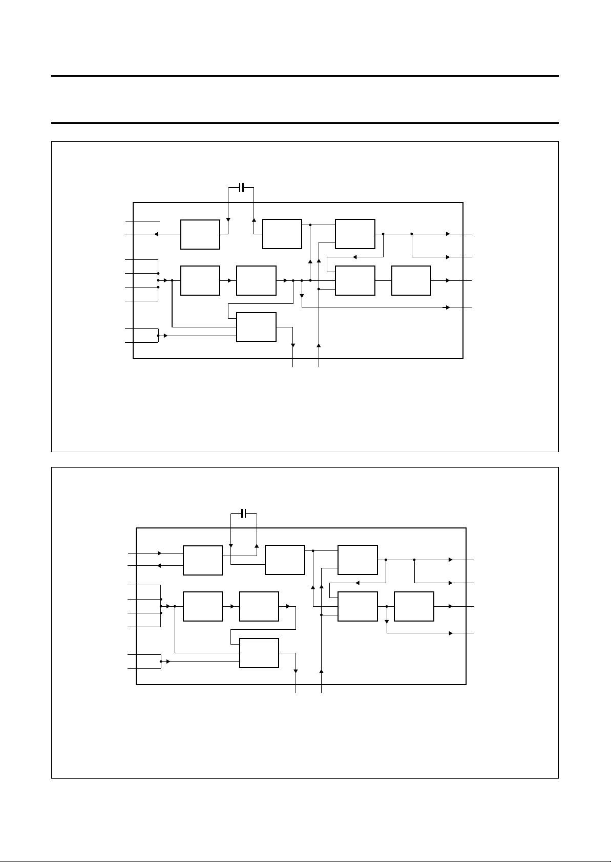
BLOCK DIAGRAM
LINER
DCOUTL
31
DCOUTR
32
HPOUTL
22
HPOUTR
23
LINEL
27
28
MODOUT
30
MODAGC
29
MRC083 - 1
DETLRFIX
RECTL
EMPHL
DCREFL
DCFBL
RVARAFOUTR
AFINR
AFOUTL
AFINL
SSD
V
SDASCLRAF
35 36 37 38 39
25 24
GAIN
2 50 49
NOISE REDUCTION
IPAF + RAF
ADJUST
2
I C
VH4 to VH0
HSF
HSL and HSR
LPF
AUDIO
SAOL,
SAOR,
SAON
LPF
AUDIO
NSS, NSH
and NSL
1834
XS
33
NOISE REDUCTION
46 45 44 43 42
47
658 3 4 48 527109
n.c. XS
LININ
DCREFR RECTR
handbook, full pagewidth
Fig.1 Block diagram.
AND-
AND-
HOLD
HOLD
SAMPLE-
SAMPLE-
MUTE
ENVOUT
HID
FADJL
ref
V
SSA1
V
SSH
V
DDA1
V
DDH
V
SSA2
V
DDA2
V
DDD
V
64
4041211920595713 51 11 12 14 17 16 15 1
MUTE
ONE
SCHOT
ref
SUPPLY AND V
NTSC
LOOP
LEVEL
60
FILTER
DETECT
NTSC
AUDIO
CLIPPER
61
ϕ
HF
LIMITER
FMINL
1.3 MHz
1.4 MHz
RAF
CCO
CCO
1.7 MHz
1.8 MHz
HF
LPF
56
FMOUT
ϕ
HF
LPF
HF
55
FMINR
1995 Mar 21 3
AUDIO
CLIPPER
LIMITER
VL5 to VL0
LOOP
FILTER
VR5 to VR0
TDA9610H
54
n.c.62n.c.63n.c.
ISH and ISL
53
FADJR TUNL TUNR CINL CINR EXT1L EXT1R EXT2L EXT2R EXN1 EXN2 LINOUT DCFBR EMPHR DETR
2658
i.c. i.c.
Page 4

Philips Semiconductors Product specification
Audio FM processor for VHS hi-fi audio TDA9610H
PINNING
SYMBOL PIN DESCRIPTION
AFINL 1 audio input for either audio clipper (record) or noise reduction (playback) of left
channel
AFOUTL 2 audio output from either sample-and-hold (playback) or noise reduction (record and
loop-through) of left channel
EXT2L 3 input selector for left channel
EXT2R 4 input selector for right channel
EXT1L 5 input selector for left channel
EXT1R 6 input selector for right channel
CINL 7 input selector for left channel
CINR 8 input selector for right channel
TUNL 9 input selector for left channel
TUNR 10 input selector for right channel
ENVOUT 11 level detector output; external capacitor required for filtering
MUTE 12 mute timing; external capacitor required for timing playback mute
V
DDD
RAF 14 overrule the I
V
SSD
SDA 16 I
SCL 17 I
XS 18 auxiliary switch; digital output controlled by I
V
DDA1
V
DDH
V
SSH
HPOUTL 22 headphone drive output left
HPOUTR 23 headphone drive output right
RVAR 24 gain adjustment of noise reduction by means of a resistor to ground
RFIX 25 fixed bias current generation circuit by using an external 100 kΩ resistor to ground
i.c. 26 pin internally connected to die pad; preferably connected to ground
LINEL 27 line output left
LINER 28 line output right
MODAGC 29 RF modulator AGC-time constant
MODOUT 30 RF modulator drive output
DCOUTL 31 VU meter drive output left
DCOUTR 32 VU meter drive output right
LININ 33 linear input
n.c. 34 not connected
DCFBL 35 DC feedback left
DCREFL 36 DC reference left
EMPHL 37 total emphasis left (20 to 240 µs)
13 digital supply voltage (+5 V)
2
C-bit RAF input or record/playback switch drive output for head
amplifier control
15 I2C-bus digital ground
2
C-bus data input
2
C-bus clock input
19 analog supply voltage 1 (+12 V)
20 headphone supply voltage (+12 V)
21 headphone ground
2
C-bit XS
1995 Mar 21 4
Page 5

Philips Semiconductors Product specification
Audio FM processor for VHS hi-fi audio TDA9610H
SYMBOL PIN DESCRIPTION
RECTL 38 rectifier DC decoupling left
DETL 39 attack/recovery timing left
V
ref
V
SSA1
DETR 42 attack/recovery timing right
RECTR 43 rectifier DC decoupling right
EMPHR 44 total emphasis right (20 to 240 µs)
DCREFR 45 DC reference right
DCFBR 46 DC feedback left
LINOUT 47 linear output
EXN1 48 EXN input (external normal input); mono input selectable to linear output
AFOUTR 49 audio output from either sample-and-hold (playback) or noise reduction (record and
AFINR 50 audio input for either audio clipper (record) or noise reduction (playback) of right
HID 51 head identification pulse input for sample-and-hold circuits
EXN2 52 EXN input (external normal input); mono input selectable to linear output
FADJR 53 frequency adjustment of right channel oscillator by means of a variable resistor
n.c. 54 not connected; preferably connected to ground
FMINR 55 1.7 to 1.8 MHz input for limiter
FMOUT 56 FM output
V
DDA2
i.c. 58 pin internally connected to die pad; preferably connected to ground
V
SSA2
NTSC 60 digital output controlled by I
FMINL 61 1.3 to 1.4 MHz input for limiter
n.c. 62 not connected; preferably connected to ground
n.c. 63 not connected; preferably connected to ground
FADJL 64 frequency adjustment of left channel oscillator by means of a variable resistor
40 noise filtering of 3.8 V reference voltage; external capacitor required for filtering
41 analog ground for LF circuits
loop-through) of right channel
channel
57 analog supply voltage (+5 V)
59 analog ground for HF circuits
2
C-bit NTSC
1995 Mar 21 5
Page 6
Philips Semiconductors Product specification
Audio FM processor for VHS hi-fi audio TDA9610H
handbook, full pagewidth
AFINL
AFOUTL
EXT2L
EXT2R
EXT1L
EXT1R
CINL
CINR
TUNL
TUNR
ENVOUT
MUTE
V
DDD
RAF
V
SSD
SDA
SCL
XS
V
DDA1
FADJL
n.c.
n.c.
FMINL
64
63
62
61
1
2
3
4
5
6
7
8
9
10
11
12
13
14
15
16
17
18
19
SSA2VDDA2
NTSC
V
60
59
TDA9610H
i.c.
58
FMOUT
FMINR
57
56
55
n.c.
54
FADJR
53
EXN2
52
51
50
49
48
47
46
45
44
43
42
41
40
39
38
37
36
35
34
33
HID
AFINR
AFOUTR
EXN1
LINOUT
DCFBR
DCREFR
EMPHR
RECTR
DETR
V
SSA1
V
ref
DETL
RECTL
EMPHL
DCREFL
DCFBL
n.c.
LININ
20
21
22
23
24
25
SSH
DDH
V
V
HPOUTL
HPOUTR
RVAR
RFIX
Fig.2 Pin configuration.
1995 Mar 21 6
26
i.c.
27
LINEL
28
LINER
29
30
MODOUT
MODAGC
31
32
DCOUTL
DCOUTR
MKA319 - 1
Page 7

Philips Semiconductors Product specification
Audio FM processor for VHS hi-fi audio TDA9610H
FUNCTIONAL DESCRIPTION
The IC is intended for use within the audio FM system of
VHS video recorders. Three modes of operation can be
distinguished:
• Record mode
• Playback mode
• Loop-through mode.
Switching and control of the three modes is done by the
I2C-bus.
Record mode
The audio signal, selected from the four stereo audio
inputs (EXT1L, EXT1R, EXT2L, EXT2R, CINL, CINR,
TUNL and TUNR), is fed to the volume control stage
(separate for left [L] and right [R]). The information for
LINOUT is, after summing of L and R, derived from either
one of the four stereo inputs or the volume control output
or one of the mono inputs (EXN1 and EXN2). After the
Low-Pass Filter (LPF) and signal compression in the noise
reduction (NR) and filter block the audio signal is available
at AFOUTL and AFOUTR. The compressed signal is now
FM modulated on a RF carrier in the PLL block. After
low-pass filtering and summation of both RF carriers
(L and R) the signal is available at FMOUT.
The output select block offers the possibility to choose
eight different audio signal modes:
1. Stereo.
2. Left.
3. Right.
4. Mono.
5. Normal.
6. Mixed stereo (stereo + LININ).
7. Mixed left (left + LININ).
8. Mixed right (right + LININ).
The headphone select block offers the possibility to
choose either the output select signal or four independent
audio signal modes (stereo, left, right and normal) for the
output stages HPOUTL and HPOUTR.
HPOUTL and HPOUTR, with common volume control for
L and R, is suitable for direct headphone drive.
DCOUTL and DCOUTR are intended for VU meter drive.
It is connected to the selected stereo audio input after the
volume control block. The output signal at
DCOUTL and DCOUTR is proportional to the square root
of the recorded audio signal (see Fig.3).
Playback mode
The two FM modulated RF carriers, present at the two
FMINL and FMINR inputs after being band-pass filtered,
are demodulated in the PLL block. The LF audio signal is
fed through a sample-and-hold circuit to suppress
head-switching noise. The demodulated audio signal is
available at AFOUTL and AFOUTR. The audio signal is
low-pass filtered and expanded in the noise reduction (NR)
and filter block. The resulting audio signal is available after
the output and headphone select blocks for all four output
stages (LINEL, LINER, MODOUT, HPOUTL, HPOUTR,
DCOUTL and DCOUTR). The functionality of the output
and headphone select blocks is identical to the record
mode. During playback DCOUTL and DCOUTR are
connected to the headphone select block.
The functionality of the input and normal select blocks is
also identical to record mode (see Fig.3), which offers the
possibility to control (other) audio signals independently
for LINOUT (see Fig.4).
Loop-through mode
This mode is similar to the record mode (see Fig.3), except
for the FMOUT pin, which is inactive, and the RAF output
which is active LOW (see Fig.5).
These audio signal modes are selectable for the output
stages LINEL, LINER and MODOUT. The standard audio
output is LINEL and LINER, e.g. for SCART output.
MODOUT is a mono audio output, with an
overload-protecting AGC, to drive an external
RF modulator.
1995 Mar 21 7
Page 8
Philips Semiconductors Product specification
Audio FM processor for VHS hi-fi audio TDA9610H
AFINL/R AFOUTL/R
2,491,50
VOLUME
CONTROL
NORMAL
SELECT
NR
AND
FILTER
47 33
LINOUT LININ
OUTPUT
SELECT
HEAD-
PHONE
SELECT
VOLUME
CONTROL
TDA9610H
27,28
30
22,23
31,32
MKA359 - 1
LINEL/R
MODOUT
HPOUTL/R
DCOUTL/R
FMINL/R
FMOUT
EXT2L/R
EXT1L/R
CINL/R
TUNL/R
EXN1
EXN2
61,55
56
3,4
5,6
7,8
9,10
48
52
PLL
INPUT
SELECT
FMINL/R
FMOUT
EXT2L/R
EXT1L/R
CINL/R
TUNL/R
EXN1
EXN2
61,55
56
3,4
5,6
7,8
9,10
48
52
Fig.3 Record mode.
AFINL/R AFOUTL/R
2,491,50
PLL
INPUT
SELECT
VOLUME
CONTROL
NORMAL
SELECT
NR
AND
FILTER
47 33
LINOUT LININ
OUTPUT
SELECT
HEAD-
PHONE
SELECT
VOLUME
CONTROL
TDA9610H
27,28
30
22,23
31,32
MKA360 - 1
LINEL/R
MODOUT
HPOUTL/R
DCOUTL/R
Fig.4 Playback mode.
1995 Mar 21 8
Page 9
Philips Semiconductors Product specification
Audio FM processor for VHS hi-fi audio TDA9610H
AFINL/R AFOUTL/R
2,491,50
VOLUME
CONTROL
NORMAL
SELECT
NR
AND
FILTER
47 33
LINOUT LININ
OUTPUT
SELECT
HEAD-
PHONE
SELECT
VOLUME
CONTROL
TDA9610H
27,28
30
22,23
31,32
MKA361 - 1
LINEL/R
MODOUT
HPOUTL/R
DCOUTL/R
FMINL/R
FMOUT
EXT2L/R
EXT1L/R
CINL/R
TUNL/R
EXN1
EXN2
61,55
56
3,4
5,6
7,8
9,10
48
52
PLL
INPUT
SELECT
Fig.5 Loop-through mode.
I2C-bus
Bus specification in accordance with I2C-bus specification. Full details of the I2C-bus are given in the document
I2C-bus and how to use it”
. This document may be ordered using the code 9398 393 40011.
“The
The address and data bytes of the TDA9610H are shown in Table 1.
Table 1 TDA9610H address and data bytes
NAME ADDRESS
Slave address (B8) 1 0 111000
Control byte
Select byte
Input byte
Function byte
(1)
(2)
(3)
(4)
Record volume left byte
Record volume right byte
Headphone volume byte
(5)
(5)
(6)
0 0 0 IPAF RAF NTSC PAFM MUTE
0 0 1 SAOL SAOR SAON HSF NSS
0 1 1 0 ISH ISL NSH NSL
0 1 1 1 HSL HSR XS TEST
1 0 VL5 VL4 VL3 VL2 VL1 VL0
1 1 VR5 VR4 VR3 VR2 VR1 VR0
0 1 0 VH4 VH3 VH2 VH1 VH0
Notes
1. See Section “Control byte”.
2. See Section “Select byte”.
3. See Section “Input byte”.
4. See Section “Function byte”.
5. See Section “Record volume left and right byte”.
6. See Section “Headphone volume byte”.
1995 Mar 21 9
Page 10
Philips Semiconductors Product specification
Audio FM processor for VHS hi-fi audio TDA9610H
Power-On Reset (POR); derived from digital supply V
DDD
In the data byte descriptions [por] indicates the mode after POR.
The status of the data bytes after POR is shown in Table 2.
Table 2 TDA9610H address and data bytes after POR
NAME ADDRESS
Control byte
Select byte
Input byte
Function byte
(1)
(2)
(3)
(4)
Record volume left byte
Record volume right byte
Headphone volume byte
(5)
(5)
(6)
00010001
00111000
01100000
01110000
10110001
11110001
01010111
Notes
1. See Section “Control byte”.
2. See Section “Select byte”.
3. See Section “Input byte”.
4. See Section “Function byte”.
5. See Section “Record volume left and right byte”.
6. See Section “Headphone volume byte”.
1995 Mar 21 10
Page 11
Philips Semiconductors Product specification
Audio FM processor for VHS hi-fi audio TDA9610H
Control byte
Table 3 Bits of control byte
BIT DESCRIPTION
IPAF Inverse Playback Audio FM; see Table 4
RAF Record Audio FM; see Table 4
NTSC National Television Standards Committee; television standard; see Table 5
PAFM Playback Audio FM Mute; see Table 6
MUTE Mute; see Table 7
Table 4 Bits IPAF and RAF
IPAF RAF
(1)
0 0 playback NR and modem in playback mode
1 0 loop-through NR in record mode; modem not active [por]
0 1 record
1 1 record
MODE DESCRIPTION
(2)
(2)
NR and modem in record mode
NR and modem in record mode
Notes
1. The RAF bit can be overruled externally by applying a low-ohmic voltage to the RAF I/O (pin 14) either logic 0 or
logic 1 (0 or +5 V). The actual mode of the IC is determined by the level measured at this pin.
2. The two record modes are equal, only differing in their reaction to forcing RAF LOW at the RAF I/O pin; the status of
the IPAF bit determines whether the IC is switched to the playback or loop-through mode.
Table 5 Bit NTSC
NTSC MODE DESCRIPTION
0 PAL modem set to PAL carrier frequencies [por]
1 NTSC modem set to NTSC carrier frequencies
Table 6 Bit PAFM
PAFM
(1)
MODE DESCRIPTION
0 −
1 PB mute the signal from the modem is muted in playback mode
Note
1. Bit PAFM has the same effect as the internally generated mute signal from the modem part when no FM carrier is
detected during playback mode. If one (or both) of these signals is HIGH, the audio signal coming from the modem
is muted.
Table 7 Bit MUTE
MUTE MODE DESCRIPTION
0 −
1 full mute all audio outputs are muted [por]
1995 Mar 21 11
Page 12
Philips Semiconductors Product specification
Audio FM processor for VHS hi-fi audio TDA9610H
Select byte
Table 8 Bits of select byte
BIT DESCRIPTION
SAOL Select Audio Output Left; see Table 9
SAOR Select Audio Output Right; see Table 9
SAON Select Audio Output Normal; see Table 9
HSF Headphone Select Function; see Table 10
NSS Normal Special Select; see Table 11
Table 9 Bits SAOL, SAOR and SAON; note 1
SAOL SAOR SAON MODE DESCRIPTION
1 1 0 stereo left at LINEL, right at LINER [por]
1 0 0 left left at both LINEL and LINER
0 1 0 right right at both LINEL and LINER
0 0 0 mono left + right added at both LINEL and LINER (hi-fi mono)
1 1 1 mixed stereo left + normal added at LINEL, right + normal added at
LINER
1 0 1 mixed left left + normal added at both LINEL and LINER
0 1 1 mixed right right + normal added at both LINEL and LINER
0 0 1 normal normal (is linear audio) at both LINEL and LINER
Note
1. The bits SAOL, SAOR and SAON provide eight output select functions, left and right are the left and right hi-fi
channels, normal is the conventional audio channel, linear audio input (LININ; pin 33).
Table 10 Bit HSF; note 1
HSF MODE DESCRIPTION
0 − headphone output signals
identical to line outputs
LINEL and LINER [por]
1 headphone
select
Note
1. Normally the headphone outputs carry the same audio
signal as present at the line outputs
(LINEL and LINER), so the signal is selectable by
means of the bits SAOL, SAOR and SAON. However
when bit HSF is set HIGH, the headphone output has
its own output select function switchable with bits HSL
and HSR to stereo, left, right and normal
(see Section “Function byte”).
headphone output signals
independently selectable
Table 11 Bit NSS; note 1
NSS MODE DESCRIPTION
0 − signal at LINOUT is the mono
version of selected stereo line
input pair [por]
1 normal
special select
Note
1. Normally the bits NSH and NSL select one of the four
possible stereo line inputs (TUNL/R, CINL/R,
EXT1L/R, EXT2L/R) as the source signal for linear out.
Left and right channels of the selected input are added
to give a mono signal as output.
When bit NSS is set HIGH, four special input selects
can be made in combination with the same bits NSH
and NSL; volume controlled, tuner left (TUNL), EXN1
and EXN2 (see Section “Input byte”).
special output signals selectable
for LINOUT
1995 Mar 21 12
Page 13
Philips Semiconductors Product specification
Audio FM processor for VHS hi-fi audio TDA9610H
Input byte
Table 12 Bits of input byte
BIT DESCRIPTION
ISH Input Select HIGH; see Table 13
ISL Input Select LOW; see Table 13
NSH Normal Select HIGH; see Table 14
NSL Normal Select LOW; see Table 14
Table 13 Bits ISH and ISL; note 1
ISH ISL MODE DESCRIPTION
0 0 Tuner TUNL and TUNR selected (as hi-fi stereo input source) [por]
0 1 Cinch CINL and CINR selected
1 0 Ext1 EXT1L and EXT1R (e.g. Scart input) selected
1 1 Ext2 EXT2L and EXT2R selected
Note
1. With bits ISH and ISL the stereo input signal is selected which is fed to the hi-fi processing. One out of four stereo
sources can be selected. The terms: Tuner, Cinch, Ext1 and Ext2 are used for describing purposes only, technically
all four inputs are equal (except for the fact that tuner left (TUNL, pin 6) is also selectable by Normal Select).
Table 14 Bits NSH, NSL and NSS; note 1
NSH NSL NSS
0 0 0 Tuner TUNL and TUNR selected (as normal audio input source) [por]
0 1 0 Cinch CINLandCINR selected
1 0 0 Ext1 EXT1L and EXT1R selected
1 1 0 Ext2 EXT2L and EXT2R selected
0 0 1 Volume hi-fi input source selected; taken after record volume control
0 1 1 Exn1 additional mono input (EXN1, pin 48) selected
1 0 1 Tuner left only TUNL selected (e.g. dual language)
1 1 1 Exn2 additional mono input (EXN2, pin 52) selected
Notes
1. With bits NSH and NSL in combination with bit NSS the input signal is selected which is fed out at pin 47 (LINOUT).
With bit NSS set LOW a selection can be made between the four stereo line inputs (like the hi-fi input select). With
bit NSS set HIGH, bits NSH and NSL make a selection between four special select functions.
When a stereo input source is selected, both channels are added to obtain a mono output signal, then the output
signal at LINOUT is equal to:
(2)
MODE DESCRIPTION
LR+()
-------------------2
In the Volume mode the output signal is equal to:
Note that for the Volume mode the hi-fi input select (ISH and ISL) determines the used input source.
2. NSS from select byte.
1995 Mar 21 13
L Volume Left× R Volume Right×+()
----------------------------------------------------------------------------------------------------2
Page 14

Philips Semiconductors Product specification
Audio FM processor for VHS hi-fi audio TDA9610H
Function byte
Table 15 Bits of function byte
BIT DESCRIPTION
HSL Headphone Select Left; seeTable 16
HSR Headphone Select Right; see Table 16
XS auxiliary Switch; see Table 17
TEST Test; see Table 18
Table 16 Bits HSL, HSR and HSF; note 1
HSL HSR HSF
1 1 0 outsel headphone output signal identical to LINEL and LINER
1 0 0 outsel headphone output signal identical to LINEL and LINER
0 1 0 outsel headphone output signal identical to LINEL and LINER
0 0 0 outsel headphone output signal identical to LINEL and LINER [por]
1 1 1 stereo left at HPOUTL, right at HPOUTR
1 0 1 left left at both HPOUTL and HPOUTR
0 1 1 right right at both HPOUTL and HPOUTR
0 0 1 normal normal (is linear audio) at both HPOUTL and HPOUTR
(2)
MODE DESCRIPTION
Notes
1. Normally (bit HSF set LOW) the headphone outputs carry the same audio signal as present at the line outputs
(LINEL and LINER), so the signal is selectable by means of the bits SAOL, SAOR and SAON. However, when bit
HSF is set HIGH the headphone output has its own output select function switchable with bits HSL and HSR.
a) These special headphone selections are also active for the VU meter drive during playback.
2. HSF from select byte.
Table 17 Bit XS
XS MODE DESCRIPTION
0 − XS output LOW [por]
1 XS XS output HIGH
1995 Mar 21 14
Page 15

Philips Semiconductors Product specification
Audio FM processor for VHS hi-fi audio TDA9610H
Table 18 Bits TEST, HSL, HSR and XS; note 1
(2)
TEST
0000 − [por]
0XXX −
100X −
1 1 0 0 VCO test L in record mode; only 1.4 or 1.3 MHz at output
1 0 1 0 VCO test R in record mode; only 1.8 or 1.7 MHz at output
1 1 1 0 Test not for application
1 1 0 1 Test not for application
1 0 1 1 Test not for application
1 1 1 1 Test not for application
Notes
1. X = don’t care.
2. With TEST bit set HIGH, the IC can be switched between several special modes for testing and adjustment purposes,
by means of bits HSL and HSR.
HSL HSR XS MODE DESCRIPTION
Record volume left and right byte
Table 19 Record volume left/right byte; note 1
VL5 VL4 VL3 VL2 VL1 VL0
VR5 VR4 VR3 VR2 VR1 VR0
1100011 mute [por]
X X X X X X 1 mute
0000000 mute
0000010 −48 dB
0000100 −47 dB
0000110 −46 dB
0001000 −45 dB
0001010 −44 dB
0001100 −43 dB
0001110 −42 dB
0010000 −41 dB
0010010 −40 dB
0010100 −39 dB
0010110 −38 dB
0011000 −37 dB
0011010 −36 dB
0011100 −35 dB
0011110 −34 dB
0100000 −33 dB
0100010 −32 dB
0100100 −31 dB
MUTE
(2)
MODE
1995 Mar 21 15
Page 16

Philips Semiconductors Product specification
Audio FM processor for VHS hi-fi audio TDA9610H
VL5 VL4 VL3 VL2 VL1 VL0
VR5 VR4 VR3 VR2 VR1 VR0
0100110 −30 dB
0101000 −29 dB
0101010 −28 dB
0101100 −27 dB
0101110 −26 dB
0110000 −25 dB
0110010 −24 dB
0110100 −23 dB
0110110 −22 dB
0111000 −21 dB
0111010 −20 dB
0111100 −19 dB
0111110 −18 dB
1000000 −17 dB
1000010 −16 dB
1000100 −15 dB
1000110 −14 dB
1001000 −13 dB
1001010 −12 dB
1001100 −11 dB
1001110 −10 dB
1010000 −9dB
1010010 −8dB
1010100 −7dB
1010110 −6dB
1011000 −5dB
1011010 −4dB
1011100 −3dB
1011110 −2dB
1100000 −1dB
1100010 0dB
1100100 1dB
1100110 2dB
1101000 3dB
1101010 4dB
1101100 5dB
1101110 6dB
1110000 7dB
1110010 8dB
MUTE
(2)
MODE
1995 Mar 21 16
Page 17

Philips Semiconductors Product specification
Audio FM processor for VHS hi-fi audio TDA9610H
VL5 VL4 VL3 VL2 VL1 VL0
VR5 VR4 VR3 VR2 VR1 VR0
1110100 9dB
1110110 10dB
1111000 11dB
1111010 12dB
1111100 13dB
1111110 14dB
Notes
1. X = don’t care.
2. MUTE from control byte.
Headphone volume byte Table 20 Headphone volume byte
VH4 VH3 VH2 VH1 VH0 MODE
0 0 0 0 0 mute
00001 −44 dB
00010 −42 dB
00011 −40 dB
00100 −38 dB
00101 −36 dB
00110 −34 dB
00111 −32 dB
01000 −30 dB
01001 −28 dB
01010 −26 dB
01011 −24 dB
01100 −22 dB
01101 −20 dB
01110 −18 dB
01111 −16 dB
10000 −14 dB
10001 −12 dB
10010 −10 dB
10011 −8dB
10100 −6dB
10101 −4dB
10110 −2dB
10111 0dB
11000 2dB
11001 4dB
MUTE
(2)
MODE
(1)
1995 Mar 21 17
Page 18

Philips Semiconductors Product specification
Audio FM processor for VHS hi-fi audio TDA9610H
VH4 VH3 VH2 VH1 VH0 MODE
11010 6dB
11011 8dB
11100 10dB
11101 12dB
11110 14dB
11111 16dB
Note
1. This is the situation after Power-On Reset (POR).
LIMITING VALUES
In accordance with the Absolute Maximum Rating System (IEC 134).
SYMBOL PARAMETER MIN. MAX. UNIT
V
V
V
V
V
T
T
DDA1
DDA2
DDH
DDD
n
stg
amb
analog supply voltage 0 13.2 V
analog supply voltage 0 5.5 V
headphone supply voltage 0 13.2 V
digital supply voltage 0 5.5 V
voltage on pins:
1, 3, 4, 5, 6, 7, 8, 9, 10, 39, 42, 48, 50 and 52 0 7.7 V
11, 12, 56 and 60 0 V
14 and 18 0 V
DDA2
DDD
V
V
storage temperature −65 +150 °C
operating ambient temperature 0 +70 °C
HANDLING
All pins are meeting the ESD requirements.
Remark: Pin 1 showed a higher sensitivity during the latch-up test and was not fully meeting the test limits.
THERMAL CHARACTERISTICS
SYMBOL PARAMETER VALUE UNIT
R
th j-a
thermal resistance from junction to ambient in free air 55 K/W
1995 Mar 21 18
Page 19

Philips Semiconductors Product specification
Audio FM processor for VHS hi-fi audio TDA9610H
DC CHARACTERISTICS
V
= 12 V; V
DDA1
levels set to 0 dB; measured in test circuit (see Fig.12); unless otherwise specified.
SYMBOL PARAMETER CONDITIONS MIN. TYP. MAX. UNIT
Supply voltages
V
DDA1
V
DDA2
V
DDH
V
DDD
Supply currents
I
DDA1
I
DDA2
I
DDH
I
DDD
Input voltages
V
I
V
55,61
DDA2
=5V; f
OUTR
= 1.8 MHz; f
= 1.4 MHz; NTSC = 0; fm= 1 kHz; T
OUTL
=25°C; all volume control
amb
analog supply voltage; pin 19 10.5 12 13.2 V
analog supply voltage; pin 57 4.75 5 5.25 V
headphone supply voltage; pin 20 10.5 12 13.2 V
digital supply voltage; pin 13 4.75 5 5.25 V
analog supply current; pin 19 − 37 46 mA
analog supply current; pin 57 record or
− 79mA
loop-through
playback − 10 13 mA
headphone supply current; pin 20 − 3.5 4.5 mA
digital supply current; pin 13 − 0.5 2 mA
DC input voltage; pins 1, 3, 4, 5, 6,
− 3.8 − V
8, 9, 10, 33, 48, 50, 52
DC input voltage internally
− 0 − V
generated; pins 55 and 61
Output voltages
V
O
DC output voltage:
pins 27 and 28 − 6 − V
pins 22 and 23 − 5.5 − V
pins 2, 30, 40, 49, 53 and 64 − 3.8 − V
pin 47 − 6 − V
pin 24 − 0.5 − V
pin 25 − 2.0 − V
pin 56 record mode − 1.2 − V
Head identification pulse input (HID; pin 51)
V
IH
V
IL
HIGH level input voltage 2.75 − 5.25 V
LOW level input voltage 0 − 2.25 V
Auxiliary switch output (XS; pin 18)
V
OH
V
OL
HIGH level output voltage IL= −500 µAV
LOW level output voltage IL= 500 µA −−0.5 V
Digital output (NTSC; pin 60)
V
OH
V
OL
HIGH level output voltage IL= −500 µAV
LOW level output voltage IL= 500 µA −−0.5 V
− 0.5 −−V
DDD
− 0.5 −−V
DDA2
1995 Mar 21 19
Page 20

Philips Semiconductors Product specification
Audio FM processor for VHS hi-fi audio TDA9610H
SYMBOL PARAMETER CONDITIONS MIN. TYP. MAX. UNIT
I/O RAF (pin 14); used as output
V
V
I
OH
OL
OH
HIGH level output voltage RAF = 1;
LOW level output voltage RAF = 0;
HIGH level output current (drive
capability)
I
OL
LOW level output current (drive
capability)
I/O RAF (pin 14); used as input (output overruled)
V
IH
V
IL
I
IH
I
IL
HIGH level input voltage 3.5 − V
LOW level input voltage 0 − 1.5 V
HIGH level input current at V
LOW level input current at V
IL= −35 µA
IL= 185 µA
RAF = 1 −35 −−µA
RAF = 0 185 −−µA
IH
IL
V
− 0.25 − V
DDD
DDD
V
0 − 0.4 V
DDD
V
−−345 µA
−−−65 µA
AC CHARACTERISTICS
Record mode
Audio input signal −8 dBV from TUNL and TUNR (pins 9 and 10).
SYMBOL PARAMETER CONDITIONS MIN. TYP. MAX. UNIT
Audio inputs (EXT1L, EXT1R, EXT2L, EXT2R, CINL, CINR, TUNL, TUNR, EXN1 and EXN2;
pins 3, 4, 5, 6, 7, 8, 9, 10, 48 and 52)
R
i
V
iAF
input resistance 100 130 − kΩ
audio input voltage −−8 dBV
Linear input (LININ; pin 33); select mode: linear
R
i
V
o
input resistance Vi= −8 dBV; f = 1 kHz 50 75 100 kΩ
line output voltage Vi= −8 dBV; f = 1 kHz −9 −8 −7 dBV
Line outputs (LINEL and LINER; pins 27 and 28)
V
o
R
o
output voltage −9 −8 −7 dBV
output resistance − 200 275 Ω
THD total harmonic distortion − 0.01 0.1 %
V
o
output voltage THD = 1%;
10 11 − dBV
RL=5kΩ;
= 2.2 nF;
C
L
TUNL ≤−3 dBV;
TUNR ≤−3 dBV;
note 1
V
n
α
cb
V
m
α
ct
noise level fi= 300 Hz to 20 kHz −−92 −88 dBV
channel balance −1 − +1 dB
volume mute level −−100 −80 dBV
crosstalk between channels one channel driven −−88 −80 dBV
1995 Mar 21 20
Page 21

Philips Semiconductors Product specification
Audio FM processor for VHS hi-fi audio TDA9610H
SYMBOL PARAMETER CONDITIONS MIN. TYP. MAX. UNIT
f
res
αctmaximum audio input crosstalk −8 dBV at a not
VU meter drive (DCOUTL and DCOUTR; pins 31 and 32); square root of output voltage (see Fig.8)
V
o
R
o
V
o
V
oz
frequency response with
respect to 1 kHz; low-pass
filter transfer
fi=20kHz −0.5 − +0.5 dB
=60kHz −−9−5dB
f
i
−−85 − dBV
selected stereo audio
input
output voltage 1.6 1.8 2.0 V
output resistance − 100 −Ω
output voltage at maximum
record level
TUNL = −3 dBV;
TUNR = −3 dBV;
V
− 0.5 − V
DDD
DDD
V
note 1
output voltage for zero-level
−−300 mV
input
RF modulator drive output; mono MODOUT; pin 30 (see Fig.9)
V
o
R
o
output voltage −10 −8 −6 dBV
output resistance − 100 −Ω
THD total harmonic distortion − 0.04 − %
V
o
output voltage at maximum
record level
TUNL = −3 dBV;
TUNR = −3 dBV;
−7 −4 −1 dBV
note 1
THD total harmonic distortion at
maximum record level
TUNL = −3 dBV;
TUNR = −3 dBV;
− 1 − %
note 1
Linear output (LINOUT; pin 47); NSS = 0
V
o
R
o
output voltage −9 −8 −7 dBV
output resistance − 200 −Ω
THD total harmonic distortion − 0.01 − %
V
n
V
o
noise level fi= 300 Hz to 20 kHz −−93 − dBV
output voltage THD = 1%;
910− dBV
RL=10kΩ;
TUNL ≤−3 dBV;
TUNR ≤−3 dBV;
NSS = 1; note 1
Headphone output (HPOUTL and HPOUTR; pins 22 and 23); headphone volume set to 0 dB
V
o
R
o
output voltage −9 −8 −7 dBV
output resistance − 3 −Ω
THD total harmonic distortion − 0.06 0.1 %
V
o
output voltage THD = 1%;
9.5 10.5 − dBV
TUNL ≤−3 dBV;
TUNR ≤−3 dBV;
RL= 250 Ω; note 1
1995 Mar 21 21
Page 22

Philips Semiconductors Product specification
Audio FM processor for VHS hi-fi audio TDA9610H
SYMBOL PARAMETER CONDITIONS MIN. TYP. MAX. UNIT
V
n
α
ct
V
mute
α
cb
Audio outputs (AFOUTL and AFOUTR; pins 2 and 49); audio output from noise reduction
V
oAF
THD total harmonic distortion − 0.15 0.3 %
V
oAF
THD total harmonic distortion at
V
n
α
cb
L linearity V
α
cc
t
att
t
rec
V
mute
FM modulator (audio input from AFINL and AFINR; pins 1 and 50)
THD total harmonic distortion ∆f = 50 kHz − 0.1 0.2 %
∆f FM frequency deviation V
∆f
max
TC temperature coefficient −±50 − 10
R
fa
f
oR
f
oL
∆f FM frequency deviation NTSC = 1;
HF output stage (FMOUT; pin 56)
V
oR(p-p)
V
oL(p-p)
noise level fi= 300 Hz to 20 kHz;
−−90 −80 dBV
tuner AC
short-circuited
crosstalk between channels one channel driven −−90 −70 dBV
headphone volume mute level −−90 −70 dBV
channel balance −1 − +1 dB
audio output voltage −13 −11.5 −10 dBV
audio output voltage at
maximum record level
TUNL = −3 dBV;
TUNR = −3 dBV;
−3.5 −2 −0.5 dBV
note 1
maximum record level
TUNL = −3 dBV;
TUNR = −3 dBV;
− 0.4 3 %
note 1
noise level fi= 300 Hz to 20 kHz −−55 −52 dBV
channel balance −1 − +1 dB
= −8to−68 dBV 28.5 30 31.5 dB
i
channel crosstalk one channel driven −−65 −50 dBV
attack time according VHS − 5 − ms
recovery time according VHS − 70 − ms
mute level MUTE = 1 −−52 − dBV
frequency response with
respect to 1 kHz; output level
maximum FM frequency
= 300 Hz −0.9 −0.2 +0.5 dB
f
i
= 10 kHz 2.9 3.9 4.9 dB
f
i
= −11.5 dBV 45 50 55 kHz
iAF
140 150 160 kHz
deviation
frequency adjust resistor left channel 22 28 35 kΩ
right channel 17 22 28 kΩ
FM centre frequency right NTSC = 1 − 1700 − kHz
FM centre frequency left NTSC = 1 − 1300 − kHz
45 50 55 kHz
= −11.5 dBV
V
iAF
right output voltage
(peak-to-peak value)
left output voltage
(peak-to-peak value)
foR= 1.8 MHz;
1stharmonic
foL= 1.4 MHz;
1stharmonic
455 510 572 mV
152 170 190 mV
−6
/K
1995 Mar 21 22
Page 23

Philips Semiconductors Product specification
Audio FM processor for VHS hi-fi audio TDA9610H
SYMBOL PARAMETER CONDITIONS MIN. TYP. MAX. UNIT
V
oR
--------- V
oL
α
3rd
R
o
Note
1. Record volume control for left and right channel set to maximum (+14 dB). Headphone volume control at 0 dB.
Playback mode
Audio output signal from the FM (de)modulator at AFOUTL and AFOUTR (pins 2 and 49).
SYMBOL PARAMETER CONDITIONS MIN. TYP. MAX. UNIT
PLL FM demodulator and limiter
α
AM
V
i(rms)
V
i max(rms)
THD total harmonic distortion ∆f = 50 kHz − 0.03 0.3 %
S/N signal-to-noise ratio V
V
oAF
α
ct
Sample-and-hold (see Fig.10)
t
h
d
AF
t
d
ratio of output voltages 2.7 3 3.3
3rdharmonic suppression 20 30 − dB
output resistance − 100 130 Ω
AM rejection V
= 1 to 100 mV;
iHF
−−80 − dBV
m = 30%
sensitivity; PLL locked
∆f = 150 kHz −−0.6 mV
(RMS value)
maximum signal level
−−200 mV
(RMS value)
∆f = 150 kHz − 0.2 1 %
=30mV;∆f = 50 kHz 55 60 − dB
iHF
AF output voltage ∆f = 50 kHz −12.5 −11.5 −10.5 dBV
crosstalk between channels L to R; R to L −−90 − dBV
hold pulse width 5 6 7 µs
audio distortion note 1 −−−76 dB
delay from HID pulse to
− 0.15 −µs
hold pulse
Mute timing (MUTE; pin 12)
V
i(rms)
mute activation level
1.1 2.0 3.5 mV
(RMS value)
t
off
t
on
switch-off duration signal to no signal − 15 − ms
switch-on duration no signal to signal − 400 − ms
Level detector output ENVOUT; pin 11 (see Fig.11)
V
o
R
o
output voltage level V
iHF(rms)
V
iHF(rms)
V
iHF(rms)
=1mV − 1.5 − V
=10mV − 3.1 − V
= 100 mV − 4.5 − V
output resistance − 20 − kΩ
Line outputs (LINEL and LINER; pins 27 and 28); audio inputs at AFINL and AFINR (pins 1 and 50): −11.5 dBV
V
o
V
n
output voltage −11 −8 −5 dBV
noise level fi= 300 Hz to 20 kHz −−93 −90 dBV
1995 Mar 21 23
Page 24

Philips Semiconductors Product specification
Audio FM processor for VHS hi-fi audio TDA9610H
SYMBOL PARAMETER CONDITIONS MIN. TYP. MAX. UNIT
THD total harmonic distortion − 0.06 0.2 %
L linearity V
α
cb
f
res
channel balance −2 − +2 dB
frequency response with
respect to 1 kHz; output
level
DC outputs (DCOUTL and DCOUTR; pins 31 and 32); square root of output voltage (see Fig.8)
V
oz
output voltage for zero input
level
Note
1. The audio distortion is measured with the HID pulse frequency set to 1 kHz (500 Hz input at pin 51). FM signal:
fm= 10 kHz; ∆f = 50 kHz. The distortion is measured with a 3 kHz 4th-order low-pass filter. The measured value at
1 kHz HID-pulse frequency is corrected with 26 dB in order to calculate the equivalent distortion at 50 Hz HID-pulse
frequency.
= −11.5 to −41.5 dBV 57 60 63 dB
iAF
fi= 300 Hz −1 +0.4 +1.8 dB
=10kHz −9.7 −7.7 −5.7 dB
f
i
HSF=1 −−300 mV
HSF=0 −−440 mV
1.5
V
oAF
(dBV)
11.5
21.5
31.5
41.5
68 48 28 12
V (dBV)
iAF
MKA362
8
Fig.6 Compression curve of noise reduction at
1 kHz; record mode. The audio output
voltage at AFOUTL and AFOUTR
(pins 2 and 49) as a function of the
audio input voltage at TUNL and TUNR
(pins 9 and 10).
8
V (dBV)
o
MKA363
1.5
V
iAF
(dBV)
11.5
21.5
31.5
41.5
68 48 28 12
Fig.7 Expansion curve of noise reduction at
1 kHz; playback mode. The audio output
voltage at LINEL and LINER
(pins 27 and 28) as a function of the audio
input voltage at AFINL and AFINR
(pins 1 and 50).
1995 Mar 21 24
Page 25

Philips Semiconductors Product specification
Audio FM processor for VHS hi-fi audio TDA9610H
5
DCOUTL/R = 2.86 x audio level
V
o
(V)
4
3
2
1
0
58 38 18 222
Fig.8 VU meter output voltage at
DCOUTL and DCOUTR (pins 31 and 32)
as a function of audio signal level.
MKA364
V (dBV)
o
0
V
o
(dBV)
5
10
15
20
58 38 18 222
MKA365
V (dBV)
o
Fig.9 Modulator output voltage at MODOUT
(pin 30) as a function of line output signal
level at LINEL and LINER (pins 27 and 28).
HID
INPUT
sample-and-
hold
CONTROL
hold
track
t
h
t
d
MKA366 - 1
time
time
Fig.10 Sample-and-hold timing waveforms.
1995 Mar 21 25
2
10
V (mV)
iHF
MKA367
3
10
V
(V)
5
o
4
3
2
1
0
1
10110
Fig.11 Level detector output voltage at ENVOUT
(pin 11) as a function of the limiter input
voltage level (RMS value) at FMINL (pin 61).
Page 26

Philips Semiconductors Product specification
Audio FM processor for VHS hi-fi audio TDA9610H
INTERNAL CIRCUITRY
SYMBOL PIN EQUIVALENT CIRCUIT DESCRIPTION
AFINL 1 audio input for either
1
25 kΩ
3.8 V
audio clipper
audio clipper (record) or noise
reduction (playback) of
left channel
MKA321 - 1
130 kΩ
130 kΩ
130 kΩ
130 kΩ
100 Ω
playback
record
3.8 V
3.8 V
3.8 V
3.8 V
noise reduction
MKA322 - 1
sample-and-hold (playback) or
noise reduction (record and
loop-through) of left channel
2
250 µA
volume
control
left
MKA320 - 1
AFOUTL 2 audio output from either
sample-and-hold
noise
reduction
EXT2L 3 input selector for left channel
3
EXT1L 5
CINL 7
TUNL 9
5
7
9
1995 Mar 21 26
Page 27

Philips Semiconductors Product specification
Audio FM processor for VHS hi-fi audio TDA9610H
SYMBOL PIN EQUIVALENT CIRCUIT DESCRIPTION
EXT2R 4 input selector for right channel
EXT1R 6
CINR 8
TUNR 10
4
130 kΩ
3.8 V
6
130 kΩ
3.8 V
8
130 kΩ
3.8 V
10
130 kΩ
3.8 V
MKA323 - 1
volume
control
right
ENVOUT 11 level detector output; external
capacitor required for filtering
500 Ω
11
20 kΩ
2 V
MKA324 - 1
MUTE 12 mute timing; external capacitor
required for timing
playback mute
V
DDD
12
18 µA
ENVOUT
275
Ω
PBMUTE
MKA325 - 1
13 digital supply voltage (+5 V)
1995 Mar 21 27
Page 28

Philips Semiconductors Product specification
Audio FM processor for VHS hi-fi audio TDA9610H
SYMBOL PIN EQUIVALENT CIRCUIT DESCRIPTION
RAF 14 overrule the I2C-bit RAF input
or record/playback switch
drive output for head amplifier
control
2
I C-RAF
21
100 µA
13
14
275
Ω
RAF
MKA326 - 1
V
SSD
SDA 16 I
15 I2C-bus digital ground
2
C-bus data input
275 Ω
16
MKA327 - 1
SCL 17 I2C-bus clock input
275 Ω
17
MKA328 - 1
XS 18 auxiliary switch; digital output
controlled by I
2
C-bit XS
MKA329 - 1
V
V
DDA1
DDH
19 analog supply voltage (+12 V)
20 headphone supply voltage
1995 Mar 21 28
18
(+12 V)
Page 29

Philips Semiconductors Product specification
Audio FM processor for VHS hi-fi audio TDA9610H
SYMBOL PIN EQUIVALENT CIRCUIT DESCRIPTION
V
SSH
HPOUTL 22 headphone drive output left
21 headphone ground
22
5 kΩ 5 kΩ
MKA330 - 1
HPOUTR 23 headphone drive output right
23
5 kΩ 5 kΩ
MKA331 - 1
RVAR 24 gain adjustment of noise
reduction by means of a
0.5 V
MKA332 - 1
24
resistor to ground
RFIX 25 fixed bias current generation
circuit by using an external
2 V
MKA333 - 1
25
100 kΩ resistor to ground
i.c. 26 pin internally connected to
die pad; preferably connected
to ground
1995 Mar 21 29
Page 30

Philips Semiconductors Product specification
Audio FM processor for VHS hi-fi audio TDA9610H
SYMBOL PIN EQUIVALENT CIRCUIT DESCRIPTION
LINEL 27 line output left
200 Ω
27
5.8 kΩ
5.8 kΩ
MKA334 - 1
LINER 28 line output right
200 Ω
28
5.8 kΩ
5.8 kΩ
MKA335 - 1
MODAGC 29 RF modulator AGC time
300 Ω
constant
MODOUT 30 RF modulator drive output
30
100 Ω
400 µA
28
MKA336 - 1
DCOUTL 31 VU meter drive output left
MKA337 - 1
100 Ω
31
1995 Mar 21 30
Page 31

Philips Semiconductors Product specification
Audio FM processor for VHS hi-fi audio TDA9610H
SYMBOL PIN EQUIVALENT CIRCUIT DESCRIPTION
DCOUTR 32 VU meter drive output right
MKA338 - 1
100 Ω
32
LININ 33 linear input
37.5 kΩ
33
37.5 kΩ
3.8 V
MKA339 - 1
n.c. 34 not connected
DCFBL 35 DC feedback left
DCREFL 36 DC reference left
EMPHL 37 total emphasis left
37
3.8 V
46.8 kΩ4.3 kΩ
36
MKA340 - 1
250 µA
100 kΩ
35
(20 to 240 µs)
RECTL 38 rectifier DC decoupling left
1296 Ω
MKA341 - 1
695 Ω695 kΩ
38
DETL 39 attack/recovery timing left
384 Ω
39
MKA342 - 1
16.4
µA
1995 Mar 21 31
Page 32

Philips Semiconductors Product specification
Audio FM processor for VHS hi-fi audio TDA9610H
SYMBOL PIN EQUIVALENT CIRCUIT DESCRIPTION
V
ref
40 noise filtering of 3.8 V
3.8 V
20 kΩ
40
MKA343 - 1
reference voltage; external
capacitor required for filtering
V
SSA1
41 analog ground for LF circuits
DETR 42 attack/recovery timing right
384 Ω
42
MKA344 - 1
16.4
µA
RECTR 43 rectifier DC decoupling right
1296 Ω
MKA345 - 1
695 Ω695 kΩ
43
EMPHR 44 total emphasis right
(20 to 240 µs)
DCREFR 45 DC reference right
DCFBR 46 DC feedback right
3.8 V
46.8 kΩ4.3 kΩ
100 kΩ
44
45
MKA346 - 1
1995 Mar 21 32
250 µA
46
Page 33

Philips Semiconductors Product specification
Audio FM processor for VHS hi-fi audio TDA9610H
SYMBOL PIN EQUIVALENT CIRCUIT DESCRIPTION
LINOUT 47 linear output
200 Ω
47
5.8 kΩ
EXN1 48 EXN input (External Normal
AFOUTR 49 audio output from either
sample-and-hold
noise
reduction
MKA349 - 1
AFINR 50 audio input for either
50
5.8 kΩ
65 kΩ
48
65 kΩ
3.8 V
playback
MKA348 - 1
MKA347 - 1
Input); mono input selectable to
linear output
sample-and-hold (playback) or
noise reduction (record and
record
25 kΩ
49
250 µA
3.8 V
loop-through) of right channel
audio clipper (record) or noise
reduction (playback) of right
channel
MKA350 - 1
100 Ω
1995 Mar 21 33
audio clipper
noise reduction
Page 34

Philips Semiconductors Product specification
Audio FM processor for VHS hi-fi audio TDA9610H
SYMBOL PIN EQUIVALENT CIRCUIT DESCRIPTION
HID 51 Head Identification pulse input
for sample-and-hold circuits
3 kΩ
51
2.5 V
MKA351 - 1
EXN2 52 EXN input (External Normal
65 kΩ
52
65 kΩ
3.8 V
MKA352 - 1
Input); mono input selectable to
linear output
FADJR 53 frequency adjustment of right
CCO-current
53
MKA353 - 1
channel oscillator by means of
a variable resistor
n.c. 54 not connected; preferably
connected to ground
FMINR 55 1.7 or 1.8 MHz input for limiter
15 pF
55
15
kΩ
kΩ
15
15
pF
3.8 V
MKA354 - 1
FMOUT 56 FM output
V
DDA2
50 Ω
57 analog supply voltage (+5 V)
56
900 µA
MKA355 - 1
1995 Mar 21 34
Page 35

Philips Semiconductors Product specification
Audio FM processor for VHS hi-fi audio TDA9610H
SYMBOL PIN EQUIVALENT CIRCUIT DESCRIPTION
i.c. 58 pin internally connected to
die pad; preferably connected
to ground
V
SSA2
NTSC 60 digital output controlled by
59 analog ground for HF circuits
2
C-bit NTSC
I
60
MKA356 - 1
FMINL 61 1.3 or 1.4 MHz input for limiter
15 pF
61
15
kΩ
3.8 V
15
kΩ
15
pF
MKA357 - 1
n.c. 62 not connected; preferably
connected to ground
n.c. 63 not connected; preferably
connected to ground
FADJL 64 frequency adjustment of left
CCO-current
64
MKA358 - 1
channel oscillator by means of
a variable resistor
1995 Mar 21 35
Page 36

Philips Semiconductors Product specification
Audio FM processor for VHS hi-fi audio TDA9610H
TEST AND APPLICATION INFORMATION
kΩ
100 µF
50 Ω
1.4 MHz
100
100 Ω
23
HPOUTR
100 µF
62
22
HPOUTL
n.c.
63
100
100 Ω
n.c.
kΩ
21
SSH
V
22 kΩ
22 kΩ
FADJL
64
( 12 V)
µF
100
20
DDH
V
DDA1
SSD
DDD
f = 1.4 MHz
V
XS
18 19
17
SCL
16
SDA
V
14 15
RAF
V
12 13
MUTE
ENVOUT
11
10
TUNR
9
TUNL
8
CINR
7
CINL
6
EXT1R
5
EXT1L
4
EXT2R
EXT2L
3
2
AFOUTL
1
AFINL
39 kΩ
( 12 V)
nF
220
4.7
µF
100
22
100
10
(8x)
µF
nF
µF
nF
MRC084 - 1
( 5 V)
Fig.12 Test circuit.
100
kΩ
220
nF
220
4.7
22
10
2.2
10
22
4.7
220 nF
10
220
4.7
10
kΩ
HS DELAY
nF
nF
µF
µF
µF
µF
µF
nF
µF
nF
µF
33
34
35
36
37
38
39
40
41
42
43
44
45
46
47
48
49
50
51
100 pF
n.c.
ref
V
HID
32
LININ
DCFBL
DCREFL
EMPHL
RECTL
DETL
SSA1
V
DETR
RECTR
EMPHR
DCFBR
LINOUT
EXN1
AFINR
EXN2
52
220 nF
100
10
DCOUTR
DCREFR
AFOUTR
FADJR
53
15 kΩ
22 kΩ
kΩ
µF
31
DCOUTL
22 kΩ
f = 1.8 MHz
kΩ
100
10
µF
n.c.54FMINR
55
1.8 MHz
30
MODOUT
50 Ω
100
10 µF
kΩ
56
3.3
10
29
MODAGC
FMOUT
pF
200
MΩ
µF
V
57
( 5 V)
28
LINER
DDA2
100
µF
kΩ
100
100
10 µF
10 µF
27
LINEL
TDA9610H
i.c.58V
kΩ
59
26
100 kΩ
i.c.
SSA2
25
60
RFIX
NTSC
2.2 kΩ
24
RVAR
FMINL
61
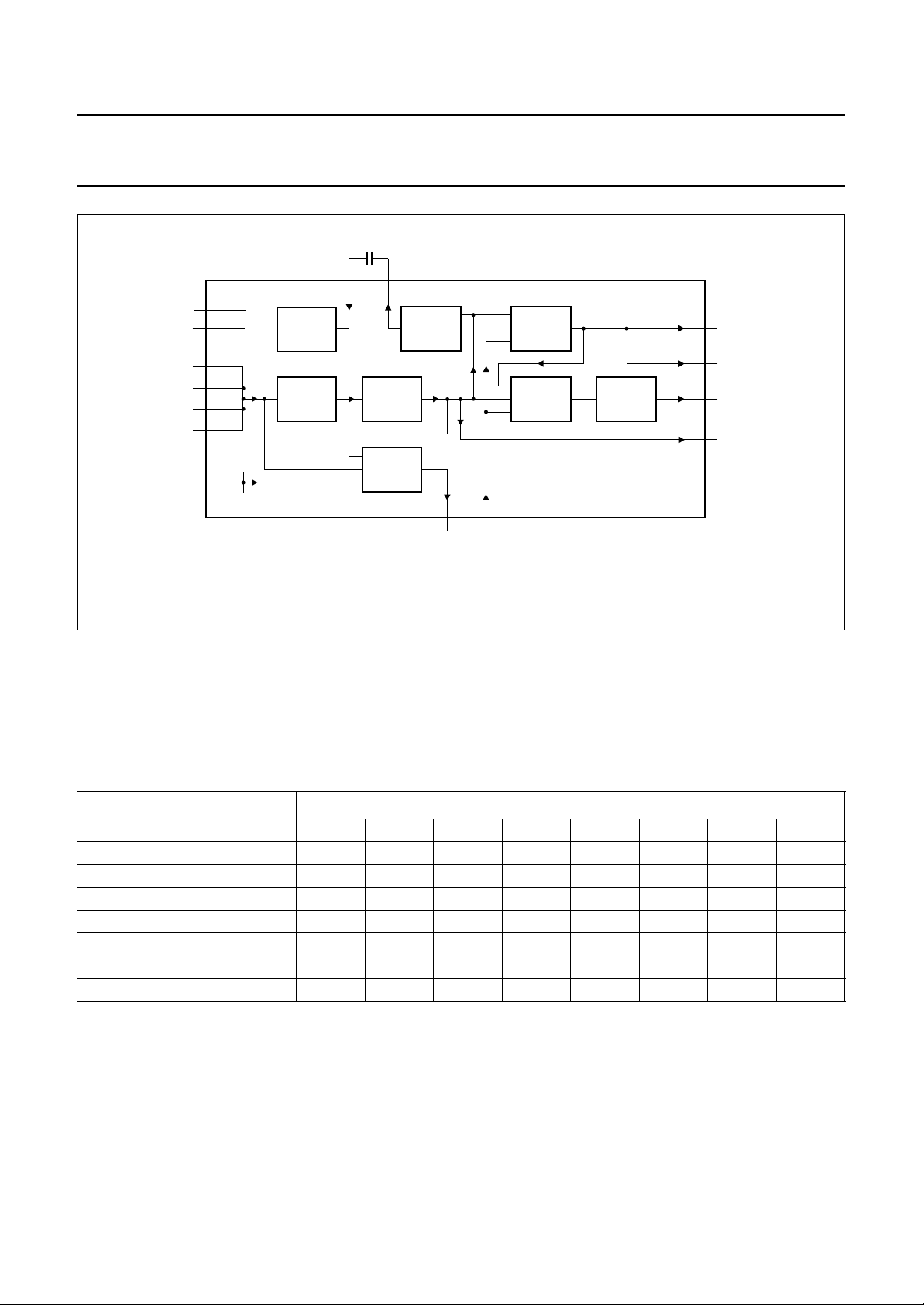
handbook, full pagewidth
1995 Mar 21 36
Page 37

Philips Semiconductors Product specification
u
Audio FM processor for VHS hi-fi audio TDA9610H
RVAR
out
DC out
L
R
kΩ
kΩ
100
100
10
10
µF
µF
31
32
10
µF
22
µF
nF
4.7
220 nF
1 kΩ
2.2 kΩ
100
4.7 µF
4.7 µF
kΩ
35 36 37 38 39
25 24
GAIN
2 50 49
NOISE REDUCTION
ADJUST
IPAF + RAF
L
120 Ω
100 µF
22
VH4 to VH0
HSF
HSL and HSR
LPF
AUDIO
headphone
10
kΩ
100 µF
R
10
kΩ
120 Ω
23
SAOL,
SAOR,
SAON
line out
L
kΩ
100
10 µF
10 µF
27
drive out
modulator
R
kΩ
100
10 µF
28
LPF
AUDIO
NSS, NSH
30
and NSL
10 µF
100 kΩ
MΩ
3.3
29
XS
NOISE REDUCTION
1834
33
46 45 44 43 42
47
MRC085 - 1
nF
220
nF
220
nF
220
nF
220
nF
220
10
22
4.7
10
µF
µF
nF
220 nF
µF
linear input
linear output
ll pagewidth
EXN2EXN1EXT2EXT1CINtuner
nF
220
2
MUTE
SCHOT
ref
SUPPLY AND V
NTSC
I C
LOOP
LEVEL
60
FILTER
DETECT
AUDIO
CLIPPER
61
1.5 kΩ
ϕ
HF
1.3 MHz
LIMITER
1.5
BPF
1.4 MHz
SAMPLE-
CCO
1.4 MHz
RAF
kΩ
AND-
HOLD
HF
LPFHFLPF
56
FM
input
AND-
SAMPLE-
HOLD
1.7 MHz
1.8 MHz
CCO
BPF
HF
55
1.5 kΩ
AUDIO
ϕ
LIMITER
1.8 MHz
CLIPPER
kΩ
1.5
FM
VL5 to VL0
LOOP
FILTER
22 nF
output
TDA9610H
54
VR5 to VR0
62
ISH and ISL
63
SDA
SCLRAF
2.2 µF
envelope
10 nF
ONE
HID
22 kΩ
1.4 MHz
64
4041211920595713 51 11 12 14 17 16 15 1
µF
2.2
22
nF
100 µH
12 V
100 µF
22
nF
100 µH
5 V
100 µF
658 3 4 48 527109
nF
220
nF
220
nF
220
nF
220
RLRLRLRL
nF
220
15 kΩ
53
2658
22 kΩ1.8 MHz
Fig.13 Application diagram.
1995 Mar 21 37
Page 38

Philips Semiconductors Product specification
Audio FM processor for VHS hi-fi audio TDA9610H
Adjustment of VCO frequency
Set the TDA9610H in record mode (NTSC off), no audio
input signal.
Measure the frequency at FMOUT (pin 56) with a
frequency counter and use the VCO TEST modes
(see Section “Function byte”) to output only the channel of
interest.
Adjust the VCO frequencies to 1.4 MHz ±10 kHz and
1.8 MHz ±10 kHz by means of the potentiometers at
pin 64 (FADJL) and pin 53 (FADJR).
When NTSC is to be the main video standard, set
NTSC on and adjust to 1.3 MHz and 1.7 MHz for optimum
frequency accuracy.
Standard FM deviation and audio level
Reference levels of frequency deviation and audio output
level are set by the resistor value at pin 24 (RVAR);
simultaneous for left, right, playback and record. Typical
resistor values can be calculated with equation:
2
∆f
------------------
R
typ
50 kHz
----------------------------------------------
A
--------------------------------------400 mV (RMS)
2.2 kΩ×=
Where:
∆f = reference FM deviation.
A = reference audio output level (1 kHz audio
frequency).
If adjustment for overall tolerance is needed, R has to be
made adjustable for the range 0.7R
typ
to 1.4R
typ
.
Set the TDA9610H in playback. Use a HF test generator to
make a carrier of 1.4 MHz with the desired modulation and
input this signal at FMINL (pin 61) or before the band-pass
filter and measure the audio output level at LINEL (pin 27).
Power-down mode
To lower the dissipation in a stand-by situation, the 12 V
supply voltage at pin 19 (V
) and pin 20 (V
DDA1
DDH
) may be
switched off, with pins 19 and 20 ‘floating’. No low-ohmic
DC path to ground may be seen from pins 19 and 20,
because this will drain extra current from the 5 V supply via
these pins to ground.
Because of the fact that the I2C circuitry and the digital
outputs RAF, NTSC and XS are supplied via the 5 V
supply, no I2C settings will be lost and the output pins can
still be used.
For instance, XS can be used to drive external mute
transistors to mute the DC jump at the line outputs when
switching the 12 V supply.
RAF I/O
The status of the I
2
C RAF bit is output at pin 14
(RAF = HIGH; record). This output can be used to switch
the audio FM head amplifier to playback and record. If
accurate fast switching of the TDA9610H is needed, this
pin can also be used as input. Thereby overruling the I2C
RAF bit. To make this possible the RAF output is current
limited.
When using the RAF pin as output, no more than 35 µA
(LOW) and 185 µA (HIGH) current may be drawn from this
pin to assure the mode of the TDA9610H is not changed.
When using the RAF pin as input, the voltage source used
must be capable of delivering at least 345 µA (forced
HIGH; >3.5 V) or sinking at least 65 µA (forced
LOW; <1.5 V).
1995 Mar 21 38
Page 39

Philips Semiconductors Product specification
Audio FM processor for VHS hi-fi audio TDA9610H
PACKAGE OUTLINE
QFP64: plastic quad flat package; 64 leads (lead length 1.95 mm); body 14 x 20 x 2.8 mm
c
y
X
51 33
52
pin 1 index
64
1
32
Z
e
w
b
p
20
19
A
E
A
H
E
E
M
2
A
A
1
detail X
Q
L
p
L
SOT319-2
(A )
3
θ
w
b
e
p
M
Z
D
D
H
D
0 5 10 mm
scale
DIMENSIONS (mm are the original dimensions)
mm
A
max.
3.20
0.25
0.05
2.90
2.65
0.25
UNIT A1A2A3b
cE
p
0.50
0.25
0.35
0.14
(1)
(1) (1)(1)
D
20.1
19.9
eH
14.1
13.9
24.2
1
23.6
Note
1. Plastic or metal protrusions of 0.25 mm maximum per side are not included.
OUTLINE
VERSION
IEC JEDEC EIAJ
REFERENCES
SOT319-2
1995 Mar 21 39
v
M
A
B
v
M
B
H
D
LLpQZywv θ
E
18.2
17.6
1.0
0.6
1.4
1.2
0.2 0.10.21.95
EUROPEAN
PROJECTION
Z
D
1.2
1.2
0.8
0.8
ISSUE DATE
E
o
7
o
0
92-11-17
95-02-04
Page 40

Philips Semiconductors Product specification
Audio FM processor for VHS hi-fi audio TDA9610H
SOLDERING
Plastic quad flat-packs
YWAVE
B
During placement and before soldering, the component
must be fixed with a droplet of adhesive. After curing the
adhesive, the component can be soldered. The adhesive
can be applied by screen printing, pin transfer or syringe
dispensing.
Maximum permissible solder temperature is 260 °C, and
maximum duration of package immersion in solder bath is
10 s, if allowed to cool to less than 150 °C within 6 s.
Typical dwell time is 4 s at 250 °C.
A modified wave soldering technique is recommended
using two solder waves (dual-wave), in which a turbulent
wave with high upward pressure is followed by a smooth
laminar wave. Using a mildly-activated flux eliminates the
need for removal of corrosive residues in most
applications.
B
Y SOLDER PASTE REFLOW
Reflow soldering requires the solder paste (a suspension
of fine solder particles, flux and binding agent) to be
applied to the substrate by screen printing, stencilling or
pressure-syringe dispensing before device placement.
Several techniques exist for reflowing; for example,
thermal conduction by heated belt, infrared, and
vapour-phase reflow. Dwell times vary between 50 and
300 s according to method. Typical reflow temperatures
range from 215 to 250 °C.
Preheating is necessary to dry the paste and evaporate
the binding agent. Preheating duration: 45 min at 45 °C.
EPAIRING SOLDERED JOINTS (BY HAND-HELD SOLDERING
R
IRON OR PULSE
-HEATED SOLDER TOOL)
Fix the component by first soldering two, diagonally
opposite, end pins. Apply the heating tool to the flat part of
the pin only. Contact time must be limited to 10 s at up to
300 °C. When using proper tools, all other pins can be
soldered in one operation within 2 to 5 s at between 270
and 320 °C. (Pulse-heated soldering is not recommended
for SO packages.)
For pulse-heated solder tool (resistance) soldering of VSO
packages, solder is applied to the substrate by dipping or
by an extra thick tin/lead plating before package
placement.
1995 Mar 21 40
Page 41

Philips Semiconductors Product specification
Audio FM processor for VHS hi-fi audio TDA9610H
DEFINITIONS
Data sheet status
Objective specification This data sheet contains target or goal specifications for product development.
Preliminary specification This data sheet contains preliminary data; supplementary data may be published later.
Product specification This data sheet contains final product specifications.
Limiting values
Limiting values given are in accordance with the Absolute Maximum Rating System (IEC 134). Stress above one or
more of the limiting values may cause permanent damage to the device. These are stress ratings only and operation
of the device at these or at any other conditions above those given in the Characteristics sections of the specification
is not implied. Exposure to limiting values for extended periods may affect device reliability.
Application information
Where application information is given, it is advisory and does not form part of the specification.
LIFE SUPPORT APPLICATIONS
These products are not designed for use in life support appliances, devices, or systems where malfunction of these
products can reasonably be expected to result in personal injury. Philips customers using or selling these products for
use in such applications do so at their own risk and agree to fully indemnify Philips for any damages resulting from such
improper use or sale.
PURCHASE OF PHILIPS I
2
C COMPONENTS
2
Purchase of Philips I
components in the I2C system provided the system conforms to the I2C specification defined by
Philips. This specification can be ordered using the code 9398 393 40011.
C components conveys a license under the Philips’ I2C patent to use the
1995 Mar 21 41
 Loading...