

Page 1
6W AUDIO AMPLIFIER WITH STAND-BY
STAND-BY FUNCTION
SUPPLYVOLTAGERANGEUPTO 30V
MUSICPOWER = 16W (R
THERMALPROTECTION
DESCRIPTION
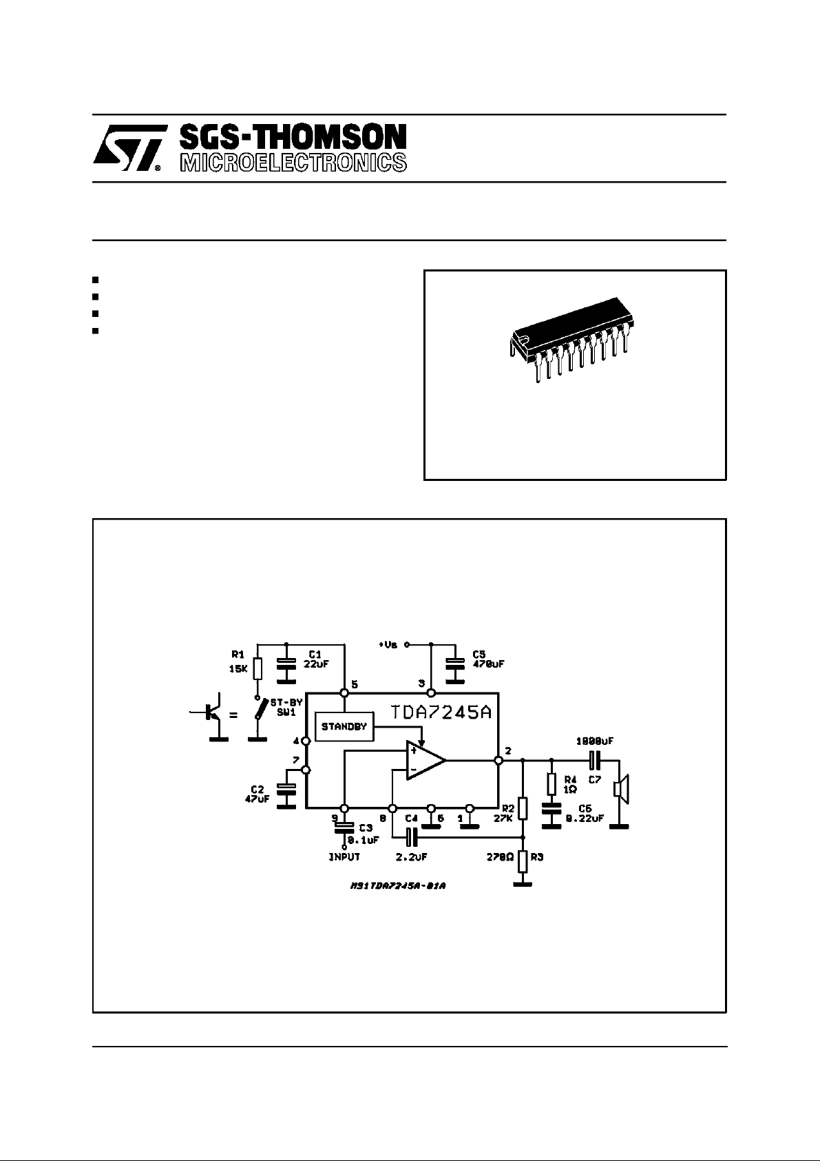
The TDA7245A is a monolithic integrated circuit
in 9+9 POWERDIP package, intended for use as
low frequency power amplifier in a wide range of
applicationsin radio and TVsets.
=4Ω, d = 10%)
L
TDA7245A
Powerdip 9+9
ORDERING NUMBER: TDA7245A
Figure 1:
Testand Application Circuit
May 1997
1/6
Page 2
TDA7245A
ABSOLUTE MAXIMUM RATINGS
Symbol Parameter Value Unit
Supply Voltage 30 V
S
Output PeakCurrent (nonrepetitive t = 100µs) 3 A
Output PeakCurrent (repetitive,f > 20Hz) 2.5 A
Power Dissipation at T
at T
amb
case
=80°C
=70°C
1
6
Storage and junction Temperature -40 to 150
P
T
stg,Tj
V
I
O
I
O
tot
W
W
°
C
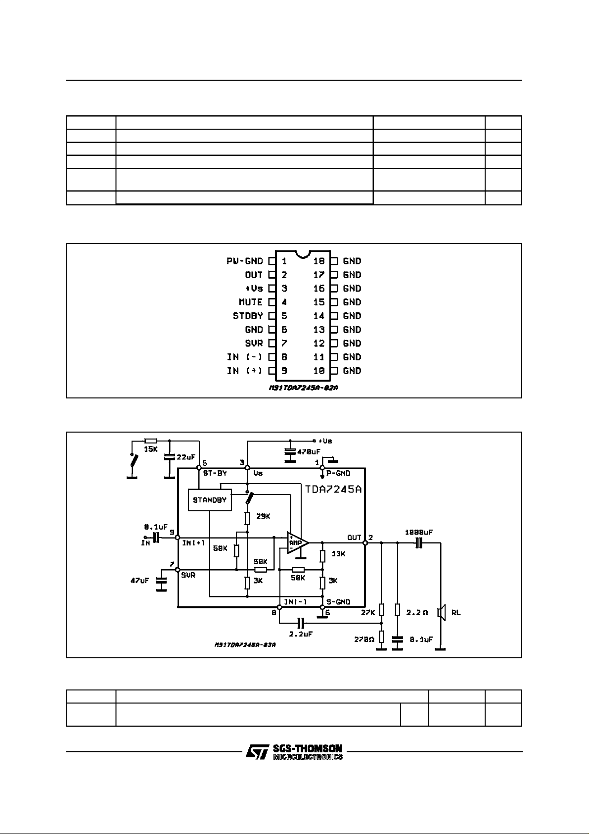
PIN CONNECTION
(Topview)
Figure 2: SchematicDiagram
THERMAL DATA
Symbol Description Value Unit
2/6
R
th j-case
Rth j-amb
Thermal Resistance junction-case
Thermal Resistance junction-ambient
Max
Max
15
70
C/W
°
C/W
°
Page 3

TDA7245A
ELECTRICAL CHARACTERISTICS (Refer to the test circuit, T
=25°C, VS= 16.5V, RL=4Ω,f=
amb
1kHz; unlessotherwise specified).
Symbol Parameter Test Condition Min. Typ. Max. Unit
V
S
V
O
I
d
P
O
d Harmonic Distortion P
R
I
BW Small signal bandwidth (-3dB) P
G
V
G
V
e
N
S/N Signal to Noise Ratio P
SVR Supply Voltage Rejection V
T
sd
Supply Voltage 12 30 V
Quiescent Output Voltage VS= 24V 11.6 V
Quiescent Drain Current VS= 28V 24 35 mA
Output Power d = 1%
V
= 16.5V, RL=4
S
V
= 20V,RL=8Ω
S
Ω
6
5
d = 10%
V
= 16.5V, RL=4
S
V
= 20V,RL=8
S
Ω
Ω
6.5
7.5
6.5
Music Power (*)
V
= 24V,d = 10%, RL=4
S
= 50mW to 4W
O
f = 1KHz
f = 10KHz
V
= 20V,RL=8Ω,
S
P
= 50mW to 3.5W
O
f = 1KHz
f = 10KHz
Ω
16
0.15
0.8
0.12
0.5
0.5 %
Input Impedance f = 1kHz 30 KΩ
= 1W 20 to 40,000 Hz
O
Voltage Gain (openloop) f = 1KHz 75 dB
Voltage Gain (closedloop) f = 1KHz 39 40 41 dB
Total Input Noise B = 22 - 22,000Hz
R
Thermal shut-down Junction
=50
Ω
s
R
=1k
Ω
s
R
= 10kΩ
s
=5W; RS= 10K
O
= 16.5V; RL=8Ω; f = 100Hz
S
R
= 10kΩ; Vr= 0.5Vrms
s
Ω
38 45 dB
1.7
2
36
86 dB
150 °C
Temperature
W
W
W
W
W
%
%
%
mV
µ
µV
V
STAND-BYFUNCTION
Symbol Parameter Test Condition Min. Typ. Max. Unit
V
st-by
I
st-by
ATT
st-by
V
t
I
d st-by
Note (*):
MUSIC POWER CONCEPT
MUSIC POWER is (according tothe IEC clauses n.268-3 of Jan 83) the maximal powerwhich the amplifier is capable of producing across the
rated load resistance (regardless of non linearity) 1 sec after the application of a sinusoidal input signalof frequency 1KHz.
According to this definitionour method of measurement comprises the following steps:
1) Set the voltage supply at the maximum operating value -20%
2) Apply a input signal in the form of a 1KHz tone burst of 1sec duration; the repetition period of the signal pulses is > 60 sec
3) The output voltage is measured 1 sec from thestart of the pulse
4) Increase the inputvoltage until the output signal show a THD = 10%
5) The music power is thenV
The targetof this method isto avoidexcessive dissipation in the amplifier.
Pin 5 DC Voltage SW1 Open (play) 6.4 V
Pin 5 Current SW1 Closed (st-by) 160 280 µA
Stand-by Attenuation f = 1kHz 70 90 dB
Stand-by Threshold (pin 5) 3.8 V
Quiescent Current @ Stand-by 2 4 mA
2
/R1,where V
out
isthe output voltage measured in the condition of point 4) and R1 is the rated load impedance
out
3/6
Page 4

TDA7245A
Figure 3: OutputPower vs. Supply Voltage
Figure4:
OutputPower vs. SupplyVoltage
4/6
Page 5

POWERDIP18 PACKAGE MECHANICAL DATA
TDA7245A
DIM.
MIN. TYP. MAX. MIN. TYP. MAX.
a1 0.51 0.020
B 0.85 1.40 0.033 0.055
b 0.50 0.020
b1 0.38 0.50 0.015 0.020
D 24.80 0.976
E 8.80 0.346
e 2.54 0.100
e3 20.32 0.800
F 7.10 0.280
I 5.10 0.201
L 3.30 0.130
Z 2.54 0.100
mm inch
5/6
Page 6

TDA7245A
Information furnished is believed to be accurate and reliable. However, SGS-THOMSON Microelectronics assumes no responsibility for the
consequences of use of such information nor for any infringement of patents or other rights of third parties which may result from its use. No
license is granted by implicationor otherwise under any patent or patent rights of SGS-THOMSON Microelectronics. Specification mentioned
in this publication are subject to change without notice. This publication supersedes and replaces all information previously supplied. SGSTHOMSON Microelectronics products are not authorized for use as critical components in life support devices or systems without express
written approval of SGS-THOMSON Microelectronics.
1997 SGS-THOMSON Microelectronics – Printed in Italy – All Rights Reserved
SGS-THOMSON Microelectronics GROUP OF COMPANIES
Australia - Brazil - Canada- China - France - Germany - HongKong - Italy - Japan - Korea - Malaysia - Malta- Morocco - The Netherlands -
Singapore - Spain - Sweden - Switzerland - Taiwan - Thailand - United Kingdom - U.S.A.
6/6
 Loading...