

Page 1
Control IC for Switched-Mode Power Supplies
using MOS-Transistors
Features
● Fold-back characteristics provides overload protection for
external components
● Burst operation under secondary short-circuit condition
implemented
● Protection against open or a short of the control loop
● Switch-off if line voltage is too low (undervoltage switch-off)
● Line voltage depending compensation of fold-back point
● Soft-start for quiet start-up without noise generated by the
transformer
● Chip-over temperature protection implemented (thermal
shutdown)
● On-chip ringing suppression circuit against parasitic
oscillations of the transformer
TDA 4605-2
Bipolar IC
P-DIP-8-1
Type Ordering Code Package
TDA 4605-2 Q67000-A5020 P-DIP-8-1
The IC TDA 4605-2 controls the MOS-power transistor and performs all necessary regulation and
monitoring functions in free running flyback converters. Because of the fact that a wide load range
is achieved, this IC is applicable for consumer as well as industrial power supplies.
The serial circuit and primary winding of the flyback transformer are connected in series to the input
voltage. During the switch-on period of the transistor, energy is stored in the transformer. During the
switch-off period the energy is fed to the load via the secondary winding. By varying switch-on time
of the power transistor, the IC controls each portion of energy transferred to the secondary side
such that the output voltage remains nearly independent of load variations. The required control
information is taken from the input voltage during the switch-on period and from a regulation winding
during the switch-off period. A new cycle will start if the transformer has transferred the stored
energy completely into the load.
Semiconductor Group 54 06.94
Page 2

TDA 4605-2
In the different load ranges the switched-mode power supply (SMPS) behaves as follow:
No load operation
The power supply is operating in the burst mode at typical 20 to 40 kHz. The output voltage can be
a little bit higher or lower than the nominal value depending of the design of the transformer and the
resistors of the control voltage divider.
Nominal operation
The switching frequency is reduced with increasing load and decreasing AC-voltage. The duty
factor primarily depends on the AC-voltage.
The output voltage is only dependent on the load.
Overload point
Maximal output power is available at this point of the output characteristic.
Overload
The energy transferred per operation cycle is limited at the top. Therefore the output voltages
declines by secondary overloading.
Semiconductor Group 55
Page 3

TDA 4605-2
Pin Definitions and Functions
Pin No. Function
1 Information Input Concerning Secondary Voltage. By comparing the
regulating voltage - obtained from the regulating winding of the transformer - with
the internal reference voltage, the output impulse width on pin 5 is adjusted to the
load of the secondary side (normal load, overload, short-circuit, no load).
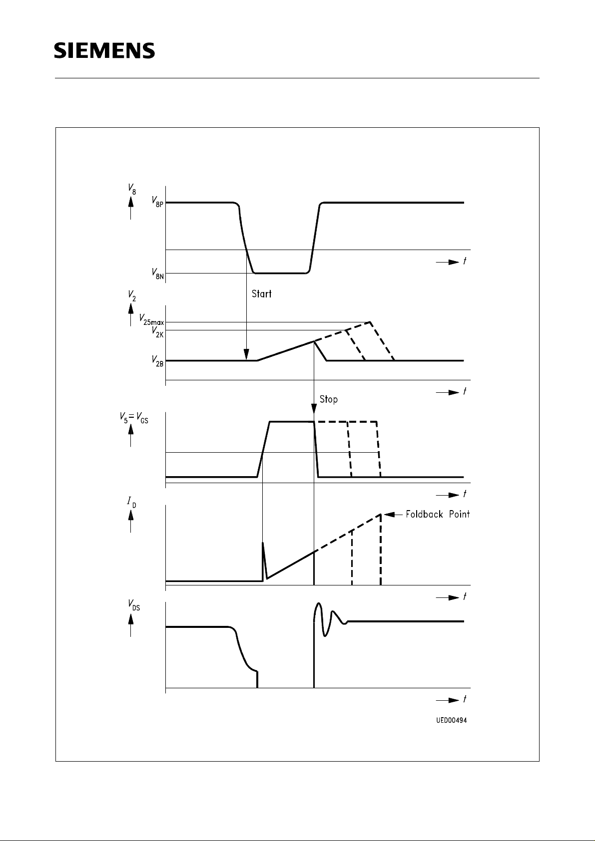
2 Information Input Regarding the Primary Current. The primary current rise in
the primary winding is simulated at pin 2 as a voltage rise by means of external
RC-circuit. If a voltage level is reached which is derived from the control voltage
at pin 1, the output impulse at pin 5 is terminated. The RC-circuit is used to set
the maximum power of the foldback point.
3 Input for Primary Voltage Monitoring: In the normal operation
between the thresholds V3Hand V
V
< V3L: SMPS is switched OFF (line voltage too low).
3
V
> V3H: Compensation of the overload point regulation (controlled by pin 2)
3
3L(V3H
> V3 > V3L).
V
is moving
3
starts at V3H: V3L = 1.7.
4 Ground
5 Output: Push-pull output for charging or discharging the gate capacity of the
power MOSFET-transistor.
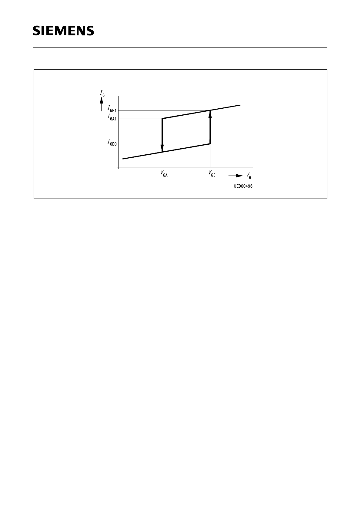
6 Supply Voltage Input. From the voltage at pin 6 a stable internal reference
voltage
supply voltage detector are derived. If V6 > V6E then V
V
and the switching thresholds V6A, V6E, V
REF
and V
6 max
is switched on. The
REF
6 min
for the
reference voltage will be switched off if V6< V6A. In addition the logic is only
enable, for V
6 min
< V6< V
6 max
.
7 Input for Soft-Start and Integrator Circuit. The capacitor connected to ground
causes a slow increase of the duration of the output pulse during start-up and an
integrating response of the control amplifier.
8 Input for the Feedback of the Oscillator. After the oscillations of the SMPS
started, every transition of the feedback voltage through zero (falling edge)
triggers an output pulse at pin 5. The trigger threshold is at + 50 mV typical.
Semiconductor Group 56
Page 4
TDA 4605-2
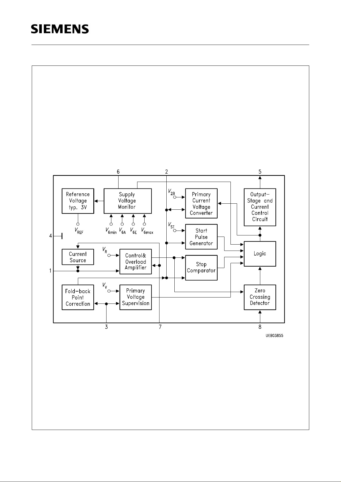
Block Diagram
Semiconductor Group 57
Page 5

TDA 4605-2
Circuit Description
Application Circuit
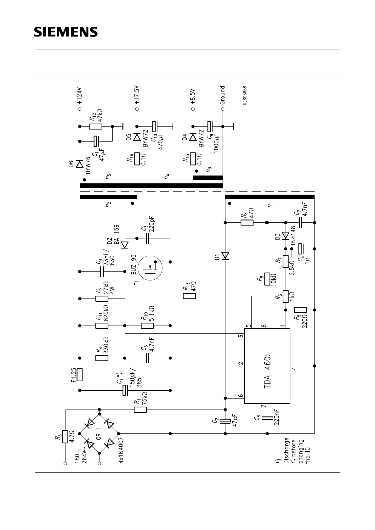
The application circuit shows a flyback converter for video recorders with an output power rating of
70 W. The circuit is designed as a wide-range power supply for AC-line voltages of 180 to 264 V.
The AC-input voltage is rectified by the bridge rectifier GR1 and smoothed by C1. The NTC limits
the rush-in current.
The IC includes an internal circuit to avoid the turn-on of the power transistor T1 because of static
charges applied to the transistors gate, during the turn-off state of the IC. The resistor R13 helps to
limit the spectrum of the radiated noise.
During the conductive phase of the power transistor T1 the current rise in the primary winding
depends on the winding inductance and the mains voltage.
The network consisting of R4-C5 is used to create a model of the sawtooth shaped rise of the
collector current. The resulting control voltage is fed into pin 2 of the IC. The RC-time constant given
by R4-C5 must be designed that way that driving the transistor core into saturation is avoided.
The ratio of the voltage divider R10/R11 is fixing a voltage level threshold. Below this threshold the
switching power supply shall stop operation because of the low mains voltage. The control voltage
present at pin 3 also determines the correction current for the foldback point.
This current added to the current flowing through R4 and represents an additional charge to C5 in
order to reduce the turn-on phase of T1. This is done to stabilize the fold-back point even under
higher mains voltages.
The control of the switched-mode power supply is done by means of a control voltage applied to
pin 1. The control voltage of winding n1 during the off-period of T1 is rectified by D3 smoothed byC
and stepped down at an adjustable ratio by R5, R6 and R7. The primary peak current, is adjusted
by the IC so that the voltage applied across the control winding, and hence the output voltages, are
at the desired level.
When the energy stored in the transformer is transferred into the load the control voltage passes
through zero. The IC detects the zero crossing via the series R9 connected to pin 8. But zero
crossings of the control voltage can also be produced by ringing of the transformer after the turn-off
of the power transistor for T1 or when a short-circuit is applied to the output of the SMPS.
The capacitor C8 is connected to pin 7. During the start-up phase this capacitor assures pulses with
a shorter duty cycle in order to keep the operating frequency outside the audible frequency range.
On the secondary side of the transformer 3 output voltages are produced using the windings n2 to
n
, rectified by D4 to D6 and smoothed byC9 to C11. The resistor R12 is used as a bleeder resistor,
5
the resistors with implemented fuse R15 and R16 protect the rectifies against short circuits in the
output circuits, which are designed to supply only small loads.
6
Semiconductor Group 58
Page 6

TDA 4605-2
Block Diagram
Pin 1
In the control and overload amplifier the control voltage applied to this pin is compared with a stable
internal reference voltage V. The output signal of this stage is fed to the "stop" comparator. If the
control voltage is rather small at pin 1 an additional current is added by means of current source
which is controlled according the level at pin 7. This additional current is virtually reducing the
control voltage present at pin 1.
Pin 2
A voltage proportional to the drain current of the switching transistor is generated by means of an
external RC-combination in conjunction with the internal functional block primary current / voltage
converter. The output of this converter is controlled by the internal functional block "logic" and is
also connected to the internal reference voltage V2B. If the voltage V2 exceeds the output voltage
of the "control and overload amplifier" the stop comparator will reset the control logic. Consequently
the output of pin 5 is switched to low potential. Further inputs for the logic stage are the outputs of
the start impulse generator with the stable reference potential VST, the supply voltage monitoring
circuit as well as the primary voltage supervision circuit.
Pin 3
The primary voltage applied here via a voltage divider is used to stabilize the fold-back point. In
addition the logic is disable if - in comparison with the internal reference voltage VV - a mains
undervoltage condition is detected.
Pin 4
Ground
Pin 5
In the output stage the output signals from the "logic" block are converted into driving signals
suitable for power MOS-transistors.
Pin 6
From the supply voltage V6 applied to this pin internally a stable reference voltage V
the switching thresholdV6A,V6E,V
All other inter reference value (VR, V2B, VST and Vv) are derived for V
6 max
andV
, for the supply voltage monitor section of the IC.
6 min
. If V6> V6E the V
REF
as well as
REF
REF
voltage source is switched on and the source is switched off if V6< V6A. In addition the logic is
enable only if V
6 min
< V6 < V
6 max
.
Semiconductor Group 59
Page 7

TDA 4605-2
Pin 7
By means of a resistor pin 7 is connected with the output of the control amplifier. If V1 is approx.
equal to the control voltage VR the control amplifier has a proportional integrating control
characteristics. The response of the control loop is derived from the capacitor connected to pin 7. If
V
is equal to 0 V the control and overload amplifier is generating a ramp-up function using the
1
capacitor connected to pin 7.
Pin 8
The zero crossing detector controlling the logic block recognizes the complete discharge of the
energy stored in the transformator core by detecting the zero crossing the positive to negative
voltage transition of the voltage at pin 8. This enables the logic for a new pulse. Parasitic oscillations
occurring at the end of a pulse cannot lead to a new pulse because of an internal circuit which
inhibits the zero detector for a certain dead time tUL after the end of each pulse.
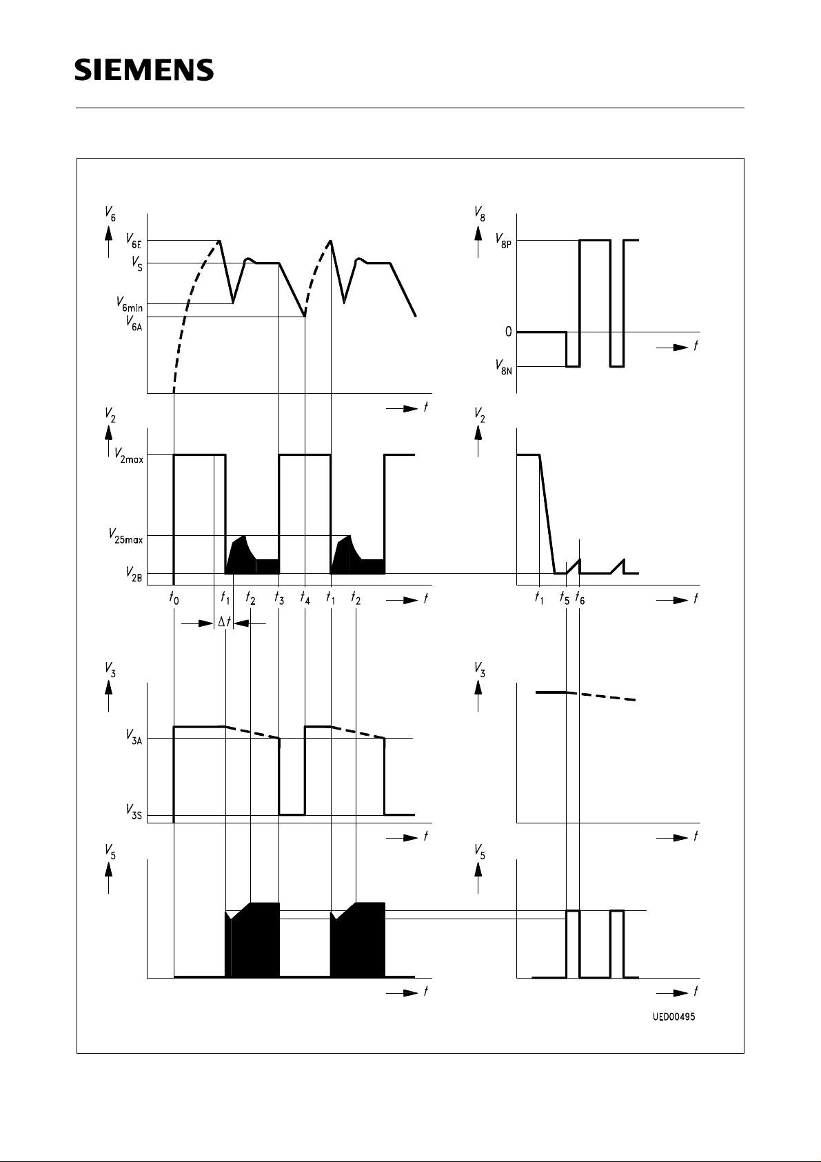
Start-Up Behaviour
The start-up behaviour of the application circuit (which is given on page 68) is explained in the
diagrams on page 70 for a line voltage barely above the lower acceptable lower limit of the mains
voltage. After applying the mains voltage at the timet0 the following built up of different voltages can
be seen:
– V6 corresponding to the half-wave charge current over R
– V2 to V
– V3 to the value determined by the divider R10/R
(typically 6.6 V)
2 max
11
1
The current drawn by the IC in this case is less than 0.8 mA.
If V6 reaches the threshold (at the time t1 in the diagram), the IC internal reference voltage is
switched on. The supply current drawn by the IC rises to 12 mA max.. The primary current/voltage
converter reducesV2 down toV2B and the start pulse generator generates the start pulses from time
point t5 to t6 in the diagram. The feedback to pin 8 starts the next pulse and so on. The width of all
pulses including the start pulse are controlled by means of the control and overload amplifier. After
turn on the IC is generating a signal at pin 7 which slowly ramping up. This signal is used to increase
the duration of the output pulses slowly (soft-start function). The max. output pulse width is limited
by means of the overload amplifier. If the feedback control voltage V1 is increasing, the overload
amplifier allows the generation of output pulses with a wider pulse width. The max. pulse width is
reached at time t2 in the diagram (V2 = V
2S max
). The IC is then operating at the fold-back point.
Thereafter the peak values ofV2 decrease rapidly, because of the IC control range. The control loop
is in a steady, operational state.
If the voltage V6 falls below the switch-off threshold V
before the foldback point is reached, the
6 min
attempt to start the SMPS is aborted (pin 5 is switched to low). As the internal circuits of the IC
remain switched on, V6 further decreases to V6A. The IC switches off; V6 can rise again (time t4 in
the diagram) and new start-up attempt begins at time t1.
Semiconductor Group 60
Page 8

TDA 4605-2
If the voltage level of the rectified mains voltage is reduced strongly under the influence of the
applied load it can happen that V3 is below the voltage level V3A - please refer to the time t3 in the
diagram. This is because if an attempt is made to start the SMPS with a too low mains voltage. The
internal primary voltage monitor circuit then clamps the voltage V3 to the voltage level V3S until the
IC switches off (V6< V6A). After this a new attempt to start the SMPS will begin at the time t1 in the
diagram.
Control Range, Overload and No-Load Behaviour
After the IC has started, it is operating in the control range. The voltage level at pin 1 is typically
400 mV. The gain of the control circuit consist of two parts: at first a fixed proportional part which is
internally fixed and an integrating part which can be set by means of the external capacitor at pin 7.
If the load is applied to the output of the SMPS, the control and overload amplifier allows wider
pulses (V5 = "H") .The peak voltage value at pin 2 increases up to V
2S max
increased further the overload amplifier begins to reduce the pulse width of the output pulse. This
point is referred to as the fold-back point of the power supply. Because of the fact that the IC supply
voltage is directly proportional to the secondary voltage, the supply voltage V6 will be reduced
according to the behaviour of the control circuit under the overload condition. If V6 falls below the
value V
, the IC will operate in the burst mode. Because of the large time constant of the start-
6 min
up circuit which is operating with half-wave rectification, only a small output power is transferred into
the load during the secondary short-circuit of the SMPS. The overload amplifier reduces the output
pulse width down to the pulse widthtpk. This pulse width must remain possible in order to permit the
IC to start up without problems from the virtual short-circuit, which every switching on with V1=0 is
representing.
. If the secondary load is
If no load is applied to the secondary side, the output pulses (V5= H) become shorter.
If the pulse width is reduced be low a certain internal limit the IC will suppress some of the output
pulses. If the load is reduced further because of the decreasing duty cycle the measurement error
of the rectifier network (R8, D3, C6 of the application circuit) is increasing and therefore the
secondary output voltage will increase, too. If the IC is operating with small pulse width of the output
pulse the control amplifier applies an additional current to the control amplifier in order to reduce the
output voltage. The value of the additional current depends on the size of the resistorsR5, R8, R7.
This can be used to compensate the increase of the secondary voltages.
Behaviour if the Chip Temperature Exceeds Predefined Limits
An integrated protection circuit against over temperature disables the internal logic if the chip
temperature is too high. The internal logic automatically checks the chip temperature and restart the
SMPS as soon as the temperature decreases to a permissible level.
Semiconductor Group 61
Page 9

Absolute Maximum Ratings
T
= – 20 to 85 ˚C; all voltages relatives to V
A
pp
Parameter Symbol Limit Values Unit Remarks
min. max.
TDA 4605-2
Voltages pin 1
pin 2
pin 3
pin 5
pin 6
pin 7
Currents pin 1
pin 2
pin 3
pin 4
pin 5
pin 6
pin 7
pin 8
Junction temperature
Storage temperature
Operating Range
Supply voltage V
Ambient temperature
Heat resistance
Junction environment
Junction package
V
V
V
V
V
V
I
1
I
2
I
3
I
4
I
5
I
6
I
7
I
8
T
T
T
R
R
1
2
3
5
6
7
j
stg
6
A
th JE
th JG
– 0.3
– 0.3
– 0.3
– 0.3
– 0.3
– 0.3
– 1.5
– 0.5
– 5
3
V
20
3
3
3
1.5
0.5
3
3
V
V
V
6
V
V
Supply voltage
V
mA
mA
mA
A
A
A
t
≤ 50 µs; v ≤ 0.1*)
p
t
≤ 50 µs; v ≤ 0.1
p
t
≤ 50 µs; v ≤ 0.1
p
mA
mA
125 ˚C
– 40 125 ˚C
7.5 15.5 V IC "on"
– 20 85 ˚C
100
70
K/W
K/W measured at pin 4
*) tp= pulse width
v= duty circle
Semiconductor Group 62
Page 10

TDA 4605-2
Characteristics
T
= 25 ˚C; VS = 10 V
A
Parameter Symbol Limit Values Unit Test Condition Test
min. typ. max.
Start-Up Hysteresis
Circuit
Start-up current drain
Switch-on voltage
Switch-off voltage
Switch-on current
Switch-off current
Voltage Clamp (
At pin 2 (
V
6
V
≤ V6E)
At pin 3 (V6≤ V6E)
I
6E0
V
6E
V
6A
I
6E1
I
6A1
= 10 V, IC switched off)
6
V
2 max
V
3 max
11 12 13 V 1
4.5 5 5.5 V 1
5.6
5.6
Control Range
Control input voltage V
Voltage gain of the
1R
–
V
R
390 400 410 mV 2
control circuit in the
control range
Primary Current Simulation Voltage
0.6 0.8 mA V6 = V
11 mA V6 = V
10 mA V6 = V
6.6
6.6
8
8
V
V
I
= 1 mA
2
I
= 1 mA
3
43 dB VR = d
(V2S – V2B)/– dV
f = 1 kHz
6E
6E
6A
1
1
1
1
1
2
1
Basic value
V
2B
0.97 1.00 1.03 V 2
Overload Range and Short-Circuit Operation
Peak value in the
V
2O
2.9 3.0 3.1 V V1 = V1R – 10 mV 2
range of secondary
overload
Peak value in the
V
2S
2.2 2.4 2.6 V V1 = 0 V 2
range of secondary
short-circuit operation
Fold-Back Point Correction
Fold-back point
– I
2
300 500 650 µA V3 = 3.7 V 1
correction current
Semiconductor Group 63
Page 11

TDA 4605-2
Characteristics (cont’d)
T
= 25 ˚C; VS = 10 V
A
Parameter Symbol Limit Values Unit Test Condition Test
min. typ. max.
Generally Valid Data (V6 = 10 V)
Voltage of the Zero Transition Detector
Circuit
Positive clamping
V
8P
0.75 V I8 = 1 mA 2
voltage
Negative clamping
V
8N
– 0.2 V I8 = – 1 mA 2
voltage
Threshold value
Suppression of
V
t
8S
UL
40 50 mV 2
4 4.5 5.5 µs2
transformer ringing
Input current –
I
8
04µAV
= 0
8
Push-Pull Output Stage
Saturation voltages
Pin 5 sourcing
Pin 5 sinking
Pin 5 sinking
V
V
V
Sat0
SatV
SatV
1.5
1.0
1.4
2.0
1.2
1.8
V
V
V
I
= – 0.1 A
5
I
= + 0.1 A
5
I
= + 0.5 A
5
1
1
1
Output Slew Rate
Rising edge + dV5/dt 20 V/µs2
Falling edge + d
V
/dt 50 V/µs2
5
Reduction of Control Voltage
Current to reduce the
– I
1
50 µA V7 = 1.1 V
control voltage
Semiconductor Group 64
Page 12

TDA 4605-2
Characteristics (cont’d)
T
= 25 ˚C; VS = 10 V
A
Parameter Symbol Limit Values Unit Test Condition Test
Circuit
Protection Circuit
Undervoltage
protection
V
for
pin 5 = V
if V6 < V
: voltage at
6
5 min
6 min
Undervoltage
protection for
V
:
6
voltage at
pin 5 = V
if V6 > V
5 min
6 max
Undervoltage
protection for
V
:
AC
voltage at
pin 5 = V
if V3 < V
5 min
3A
Over temperature at
the given chip the
temperature IC will
V
switch
to V
5
5 min
Voltage at pin 3 if one
of the protection
functions was
triggered;
(
V
will be clamped
3
until V6 < V6A) V
Current drain during
burst operation
V
6 min
V
6 max
V
3A
T
j
3Sat
I
6
min. typ. max.
7.0 7.25 7.5 V 2
15.5 16 16.5 V 2
985 1000 1015 mV V2 = 0 V 1
150 ˚C 2
0.4 0.8 V I3 = 750 µA1
8mAV
= V2 = 0 V 1
3
Semiconductor Group 65
Page 13
TDA 4605-2
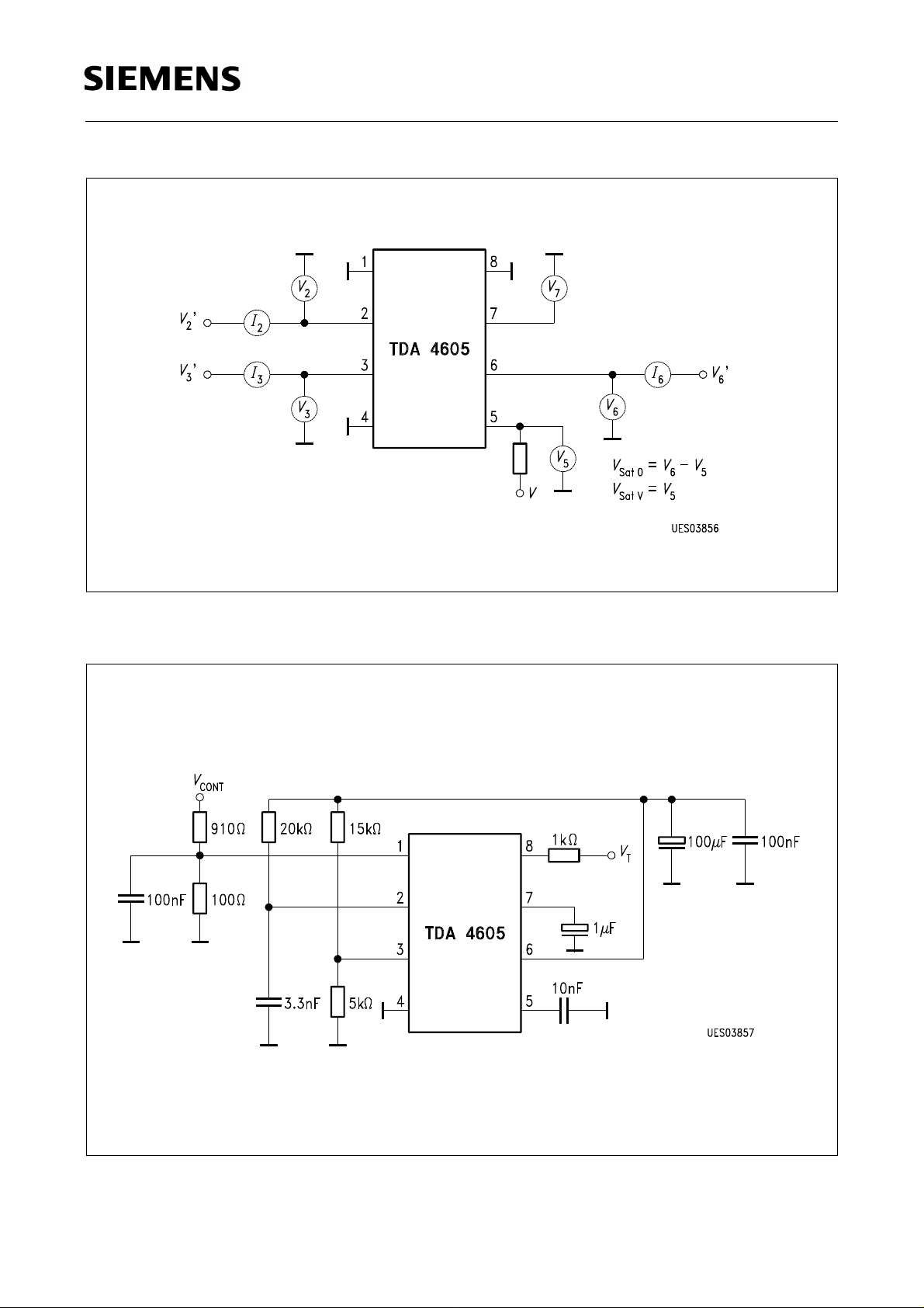
Test Circuit 1
Test Circuit 2
Semiconductor Group 66
Page 14
TDA 4605-2
Application Circuit
Semiconductor Group 67
Page 15
Diagrams
TDA 4605-2
Semiconductor Group 68
Page 16
TDA 4605-2
Semiconductor Group 69
Page 17
TDA 4605-2
Start-Up Hysteresis
Semiconductor Group 70
Page 18
TDA 4605-2
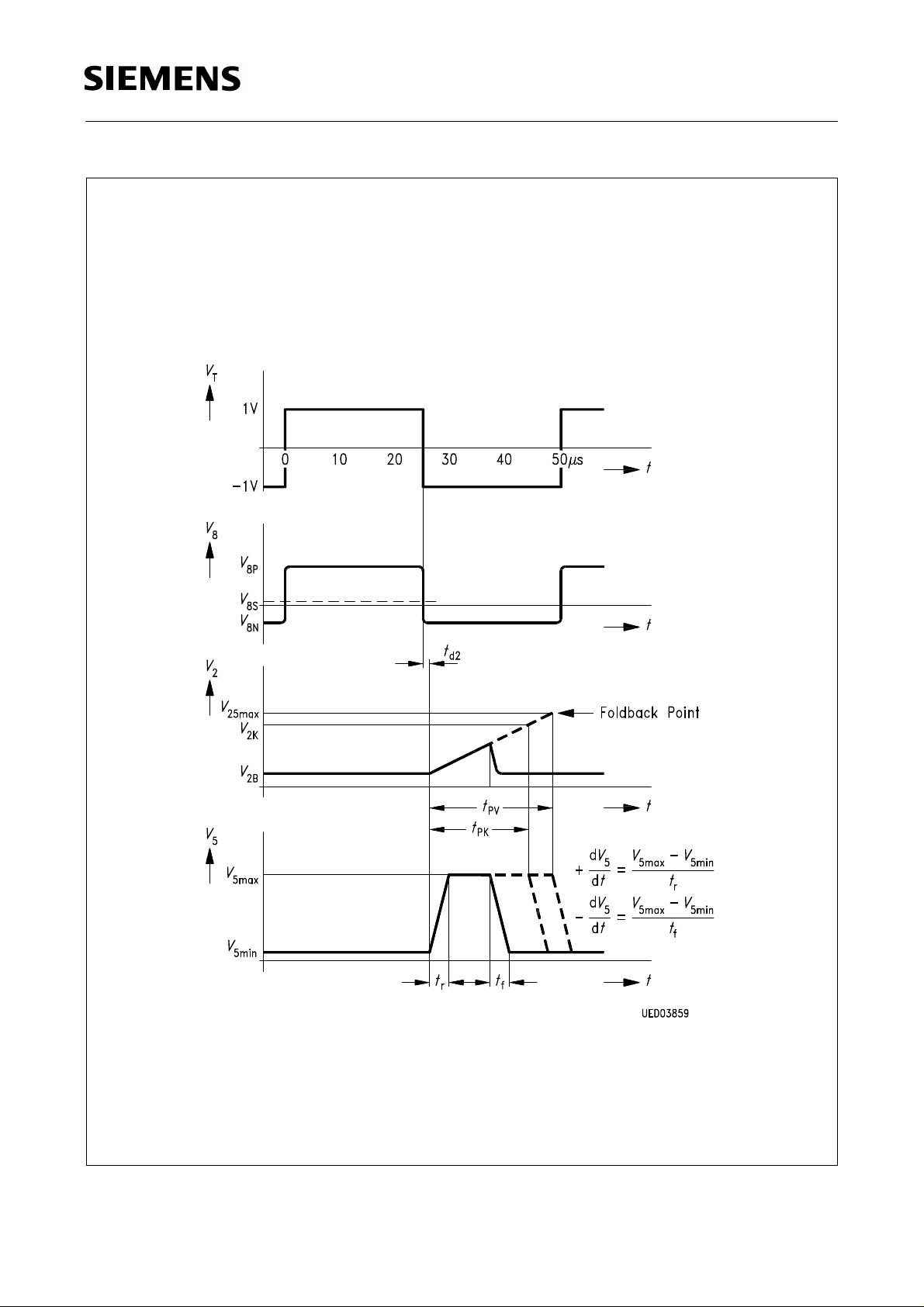
Operation in Test Circuit 2
Semiconductor Group 71
Page 19
TDA 4605-2
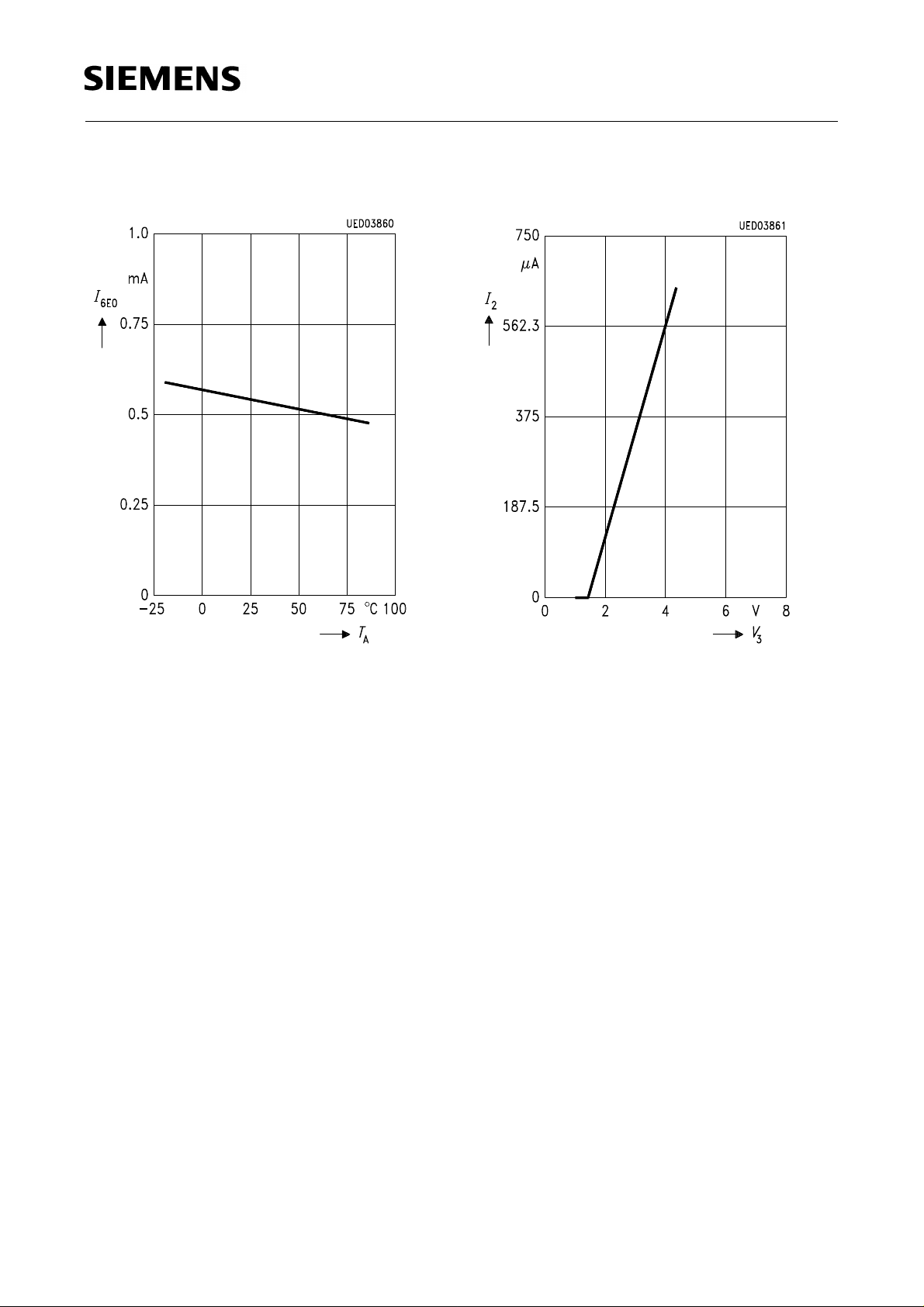
Start-Up Current as a Function of the
Ambient Temperature
Overload Point Correction as a Function of
the Voltage at Pin 3
Semiconductor Group 72
Page 20
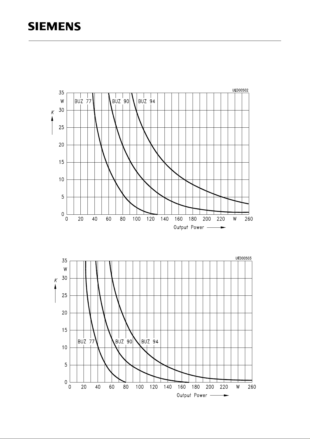
Recommended Heat Sink by 60 ˚C Ambient Temperature
Narrow Range 180 V ... 120 V ~
TDA 4605-2
Narrow Range 90 V ... 270 V ~
Semiconductor Group 73
 Loading...