

Page 1

INTEGRATED CIRCUITS
DATA SH EET
TDA1380
DCC read amplifier (READ 3)
Preliminary specification
File under Integrated Circuits, IC01
Philips Semiconductors
September 1994
Page 2
Philips Semiconductors Preliminary specification
DCC read amplifier (READ 3) TDA1380
FEATURES
• Single 3 V supply
• Low power consumption
• Differential inputs for low power head configuration
• Can be used with 1st, 2nd and 3rd generation digital
signal processing ICs
• Automatic gain control for DCC preamplifiers
• Selectable input amplifiers for A or B side of cassette
• ACC playback via DCC preamplifiers
• Uncommitted amplifiers for equalization during ACC
playback
• Low noise current sources for the sense currents of the
DCC heads
• Generates reference sense current for temperature
compensation of the write current, in recordable
application with the TDA1381
• High feedback application possible (for adjustment
minimization)
• Suitable for digital post-processor.
GENERAL DESCRIPTION
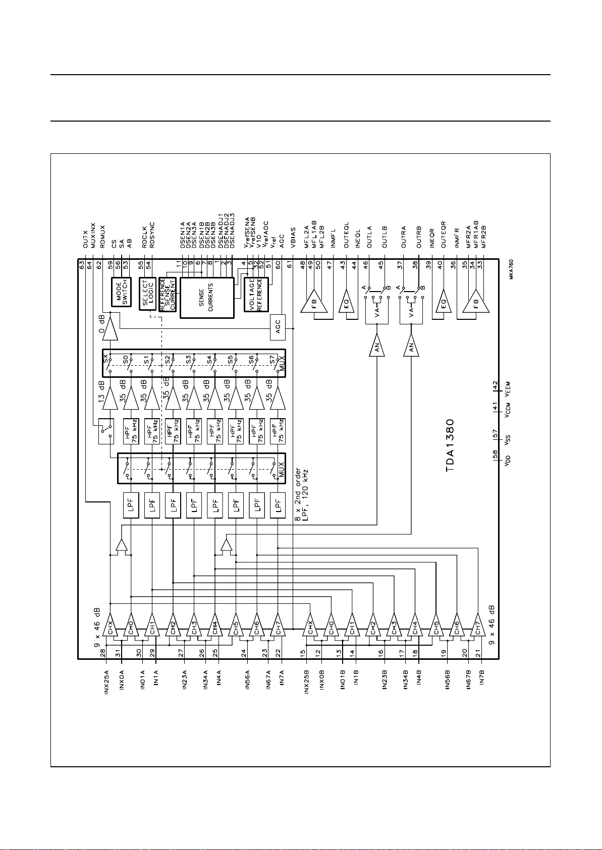
The TDA1380 amplifies, filters and multiplexes signals that
are input from an 18-channel magnetoresistive thin film
head (MRH) suitable for the DCC (Digital Compact
Cassette) and ACC (Analog Compact Cassette) systems.
The device also contains current sources to provide sense
currents through the heads and amplifiers for magnetic
feedback and biasing. Two uncommitted amplifiers are
available for analog equalization.
ORDERING INFORMATION
TYPE NUMBER
TDA1380 TQFP64
Note
1. When using IR reflow soldering it is recommended that the Drypack instructions in the
Handbook”
: (order number 9398 510 63011) are followed.
NAME DESCRIPTION VERSION
(1)
plastic thin quad flat package; 64 leads; body 10 × 10 × 1.4 mm SOT314-2
PACKAGE
“Quality Reference
September 1994 2
Page 3

Philips Semiconductors Preliminary specification
DCC read amplifier (READ 3) TDA1380
QUICK REFERENCE DATA
SYMBOL PARAMETER
CONDITIONS ON PINS
CS SA AB
V
DD
V
CCM
I
DDDCC+ICCM
I
DDACC+ICCM
I
DDRS
supply voltage −−−2.7 3.0 5.5 V
supply voltage feedback amplifiers −−−2.7 3.0 5.5 V
supply current DCC mode 1 0 X 28 39 53 mA
supply current ACC mode 1 1 X 26 35 47 mA
supply current reference sense
0 0 X 0.6 1.2 1.6 mA
current mode
I
DDAB
I
DDstb+ICCM
P
(tot)DCC
supply current sense AB mode 0 1 1 1.5 2.7 3.7 mA
supply current standby mode 0 1 0 − 0.2 0.3 mA
total power dissipation DCC mode;
10X−120 − mW
note 2
P
(tot)ACC
total power dissipation ACC mode;
11X−105 − mW
note 2
T
amb
operating ambient temperature −−−−30 − +85 °C
Notes
1. In the conditions column 0 = LOW; 1 = HIGH; X = don’t care.
2. V
DD=VCCM
= 3 V; I
DSEN
= 0; IFB=0.
(1)
MIN. TYP. MAX. UNIT
September 1994 3
Page 4
Philips Semiconductors Preliminary specification
DCC read amplifier (READ 3) TDA1380
BLOCK DIAGRAM
September 1994 4
Fig.1 Block diagram.
Page 5
Philips Semiconductors Preliminary specification
DCC read amplifier (READ 3) TDA1380
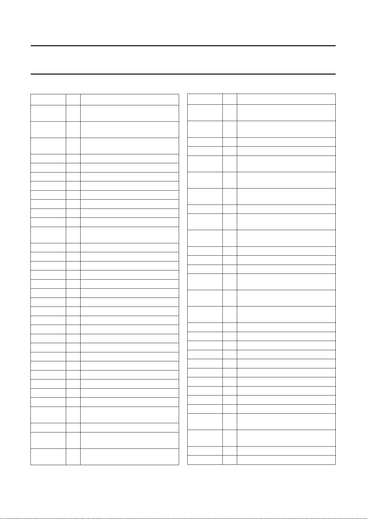
PINNING
SYMBOL PIN DESCRIPTION
DSENADJ1 1 adjustment pin for sense current 1
(A and B)
DSENADJ2 2 adjustment pin for sense current 2
(A and B)
DSENADJ3 3 adjustment pin for sense current 3
(A and B)
V
refSENA
V
refSENB
4 reference voltage output sense (A)
5 reference voltage output sense (B)
DSEN1B 6 sense current output 1 (B)
DSEN2B 7 sense current output 2 (B)
DSEN3B 8 sense current output 3 (B)
DSEN3A 9 sense current output 3 (A)
DSEN2A 10 sense current output 2 (A)
DSEN1A 11 sense current output 1 (A)
INX0B 12 auxiliary channel input/channel 0
input (B)
IN01B 13 channel 0 and 1 input (B)
IN1B 14 channel 1 input (B)
INX25B 15 channels AUX, 2 and 5 input (B)
IN23B 16 channels 2 and 3 input (B)
IN34B 17 channels 3 and 4 input (B)
IN4B 18 channel 4 input (B)
IN56B 19 channels 5 and 6 input (B)
IN67B 20 channels 6 and 7 input (B)
IN7B 21 channel 7 input (B)
IN7A 22 channel 7 input (A)
IN67A 23 channels 6 and 7 input (A)
IN56A 24 channels 5 and 6 input (A)
IN4A 25 channel 4 input (A)
IN34A 26 channels 3 and 4 input (A)
IN23A 27 channels 2 and 3 input (A)
INX25A 28 channels AUX, 2 and 5 input (A)
IN1A 29 channel 1 input (A)
IN01A 30 channels 0 and 1 input (A)
INX0A 31 auxiliary channel input/channel 0
input (A)
V10 32 reference voltage for DCC inputs
MFR2B 33 right channel feedback amplifier
output 2 (B)
MFR1AB 34 right channel feedback amplifier
output 1 (A and B)
SYMBOL PIN DESCRIPTION
MFR2A 35 right channel feedback amplifier
output 2 (A)
INMFR 36 right channel feedback amplifier
input
OUTRA 37 right channel ACC output (A)
OUTRB 38 right channel ACC output (B)
INEQR 39 right channel equalization amplifier
input
OUTEQR 40 right channel equalization amplifier
output
V
CCM
41 supply voltage for feedback
amplifiers
V
EEM
42 ground for feedback amplifiers
OUTEQL 43 left channel equalization amplifier
output
INEQL 44 left channel equalization amplifier
input
OUTLB 45 left channel ACC output (B)
OUTLA 46 left channel ACC output (A)
INMFL 47 left channel feedback amplifier input
MFL2A 48 left channel feedback amplifier
output 2 (A)
MFL1AB 49 left channel feedback amplifier
output 1 (A and B)
MFL2B 50 left channel feedback amplifier
output 2 (B)
V
ref
V
refADC
51 reference voltage output
52 ADC reference voltage output
AB 53 tape sector A or B selection input
RDSYNC 54 read sync pulse input
RDCLK 55 read clock pulse input
SA 56 select ACC mode input
V
SS
V
DD
57 ground
58 supply voltage
CS 59 chip select input
AGC 60 AGC time constant
VBIAS 61 preamplifier gain control voltage
input
RDMUX 62 output of sampled and multiplexed
auxiliary and main data signals
OUTX 63 auxiliary channel preamplifier output
MUXINX 64 auxiliary channel multiplexer input
September 1994 5
Page 6
Philips Semiconductors Preliminary specification
DCC read amplifier (READ 3) TDA1380
September 1994 6
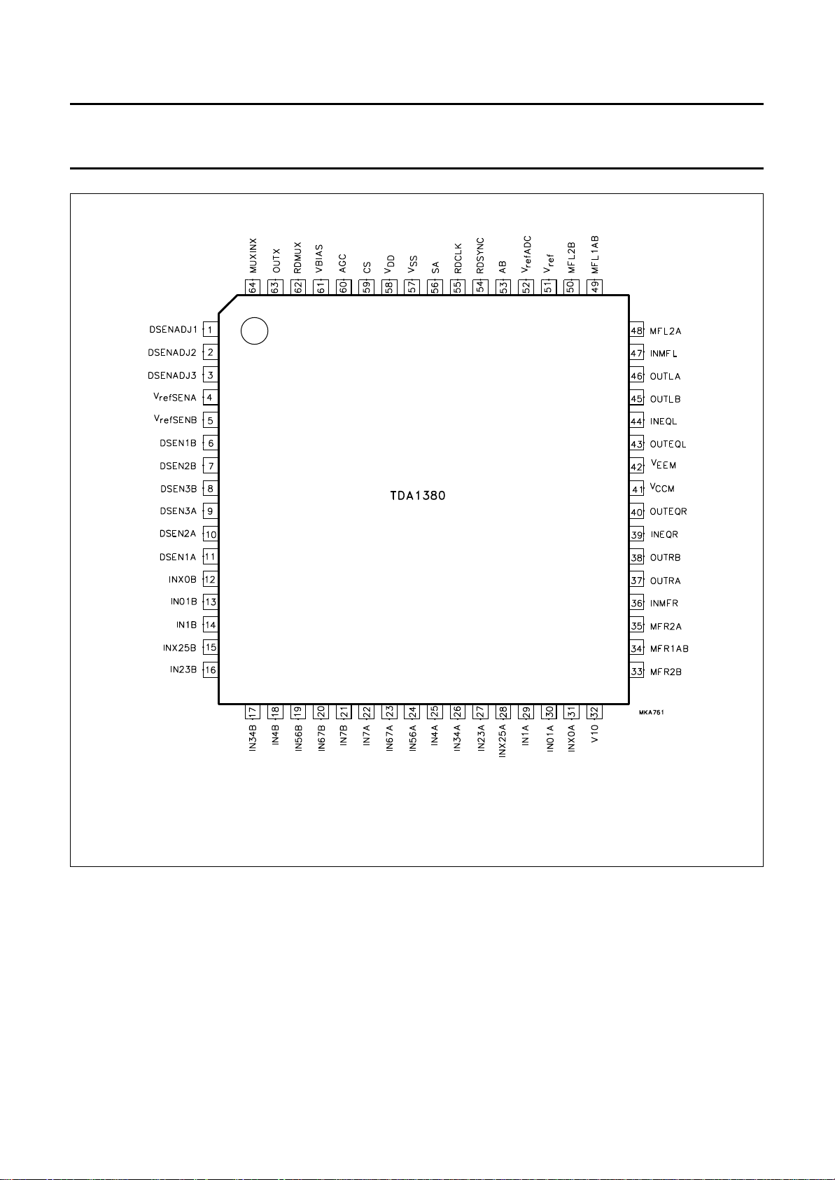
Fig.2 Pin configuration.
Page 7

Philips Semiconductors Preliminary specification
DCC read amplifier (READ 3) TDA1380
FUNCTIONAL DESCRIPTION
DCC data amplifiers and filters
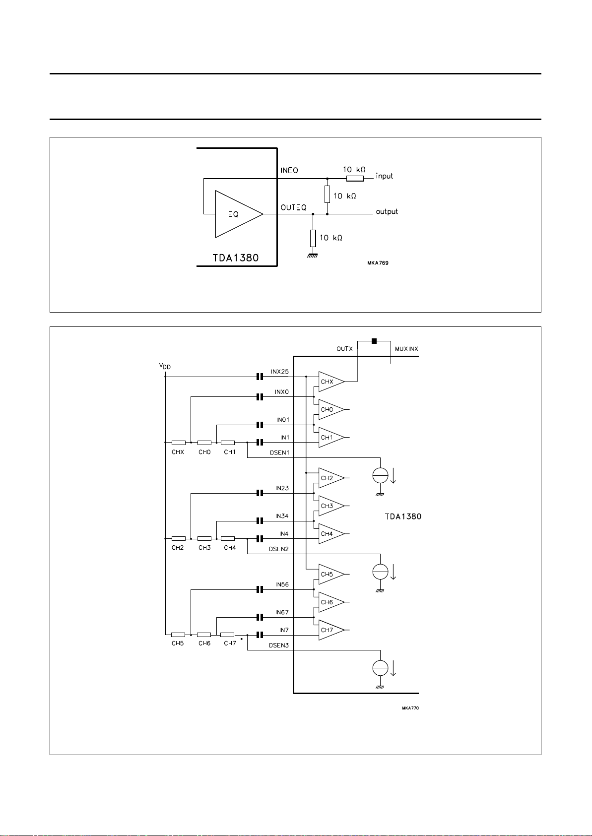
The TDA1380 has 18 low-noise preamplifiers, which are
connected to an 18-channel MRH. For each tape sector
the MRH is partitioned into three strings of three heads
(see Fig.11). Depending on the tape sector selection
signal AB, nine preamplifiers for the A-sector, or nine
preamplifiers for the B-sector of the tape are selected.
Eight of the nine channels are for the DCC main data, and
one for the auxiliary (AUX) data. The eight main data
channels have pre-equalization for frequencies from 1 kHz
up to 50 kHz (1st order highpass, −3 dB at 75 kHz), and
lowpass filtering for anti-aliasing (2nd order active, −3dB
at 120 kHz). The AUX channel has a flat frequency
response. The AUX data is continuously available at
output OUTX. This output must be AC-coupled to the
multiplexer input MUXINX. All inputs must be AC-coupled
to the MRH. The inputs are internally biased at pin V10.
The voltage at pin V10 is temperature dependent and is
not intended for external use. Pin V10 has to be decoupled
to the positive supply voltage (V
DD
).
Automatic gain control
The DCC part is equipped with an AGC circuit which
decreases the gain of the preamplifiers when the level at
RDMUX exceeds a preset value. In this way an optimum
voltage swing at the RDMUX output is obtained (for the
ADC input of SAA2051, SAA2032, SAA2023 or
SAA3323). The response time of the AGC can be set by
an external capacitor connected to pin 60. There is a fixed
relationship between the source and sink current at this
pin, resulting in a fixed relationship between the decay
time and the recover time of the preamplifier gain. The
AGC is active only in the DCC mode and can be switched
off by connecting pin 60 to V
SS
.
Multiplexer
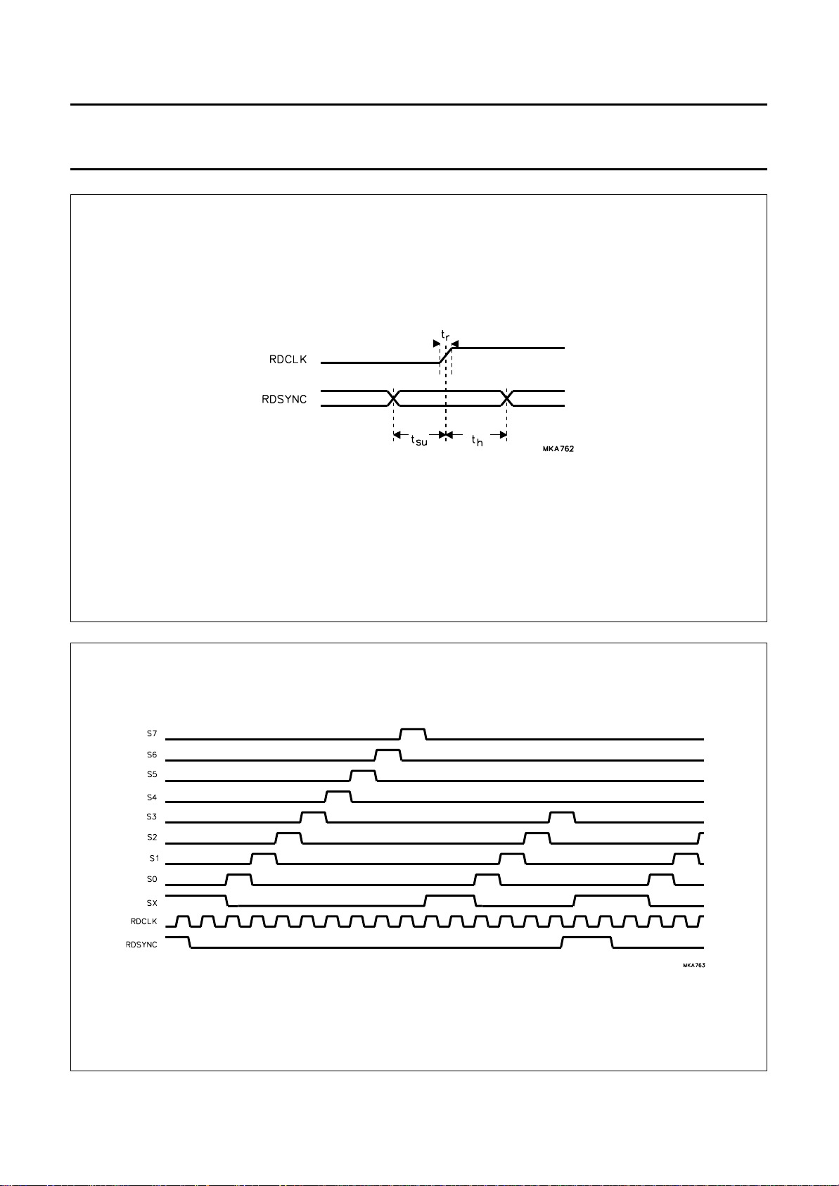
A multiplexing circuit switches the nine digital channels
sequentially to the output. The AUX data is sampled during
two clock periods, the eight main data channels are
sampled during one clock period. The effective sample
frequency is one tenth of the clock frequency at RDCLK. A
timing overview is illustrated in Fig.4.
Analog amplifiers
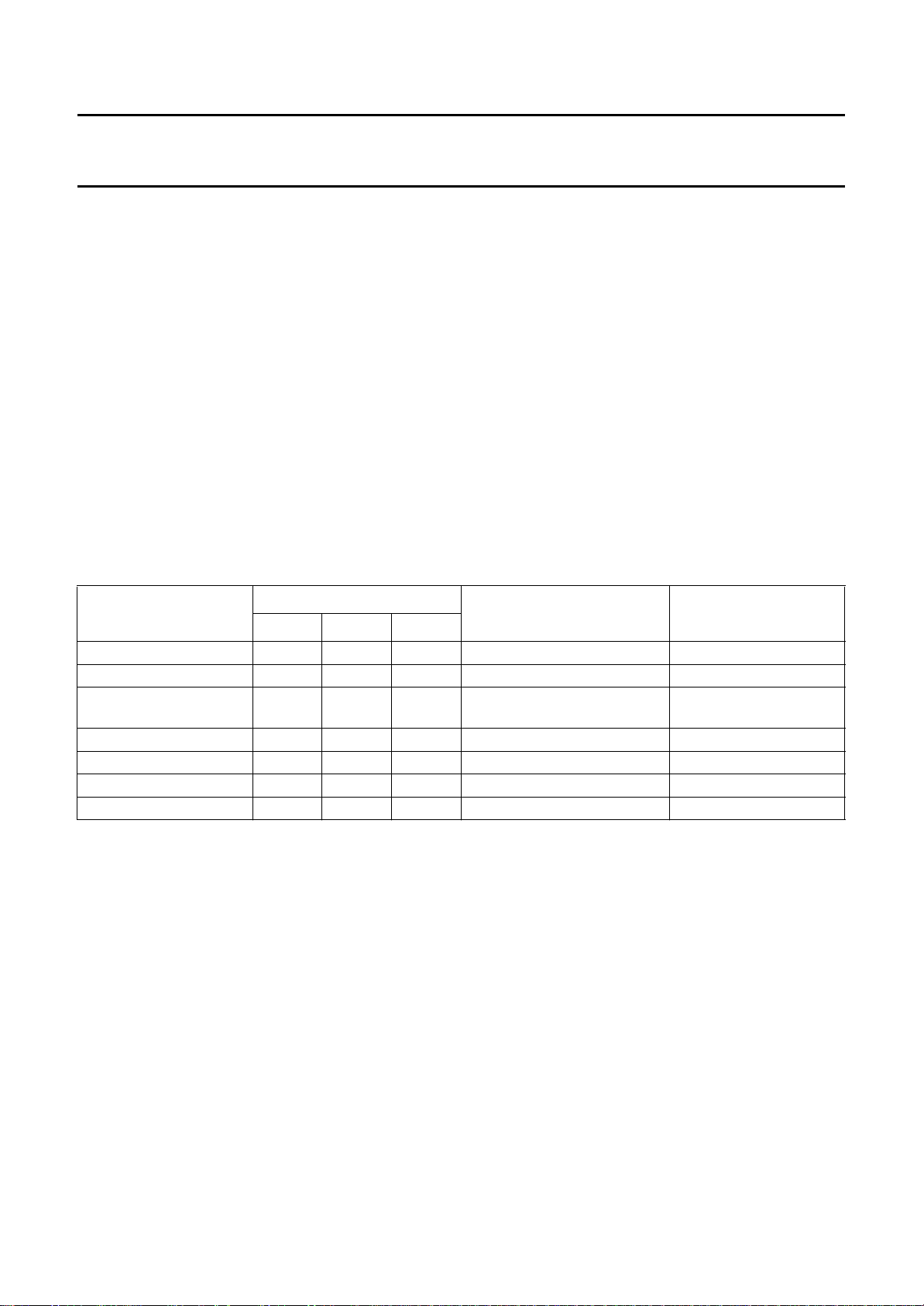
For ACC playback the TDA1380 employs four DCC
preamplifiers (per tape sector) for amplification of the left
and right analog signals. Amplifiers CHX and CH0 are
used for the left channel and CH4 and CH5 for the right
channel. The buffered left and right channel outputs are
available at four pins (see Table 1). Pins that carry no left
and right channel signals will have a DC level V
.
A
Table 1 ACC playback.
AB
1 A left V
0BV
TAPE
SELECT
OUTLA OUTLB OUTRA OUTRB REMARKS
A
A
right V
left V
A
A
right
allows separate amplitude
adjustment for sectors A and B
1 A left note 1 right note 1 allows one amplitude setting
0 B left note 1 right note 1
only for sectors A and B
(DSP operation; high feedback
operation)
Note
1. At least one of OUTLB and OUTRB are externally connected to VDD.
September 1994 7
Page 8
Philips Semiconductors Preliminary specification
DCC read amplifier (READ 3) TDA1380
Feedback amplifiers
Two feedback amplifiers are available for driving a
conductor in the MRH, thus providing magnetic feedback
to improve the linearity of the analog audio response. In
both the ACC and DCC mode, the feedback amplifiers are
used for DC biasing of the MRH. The circuit principle of the
feedback amplifiers is illustrated in Fig.9.
Current and voltage sources
Separate, adjustable low-noise current sources are
available to provide the sense currents to the MRHs. The
active current outputs are controlled by the mode switch
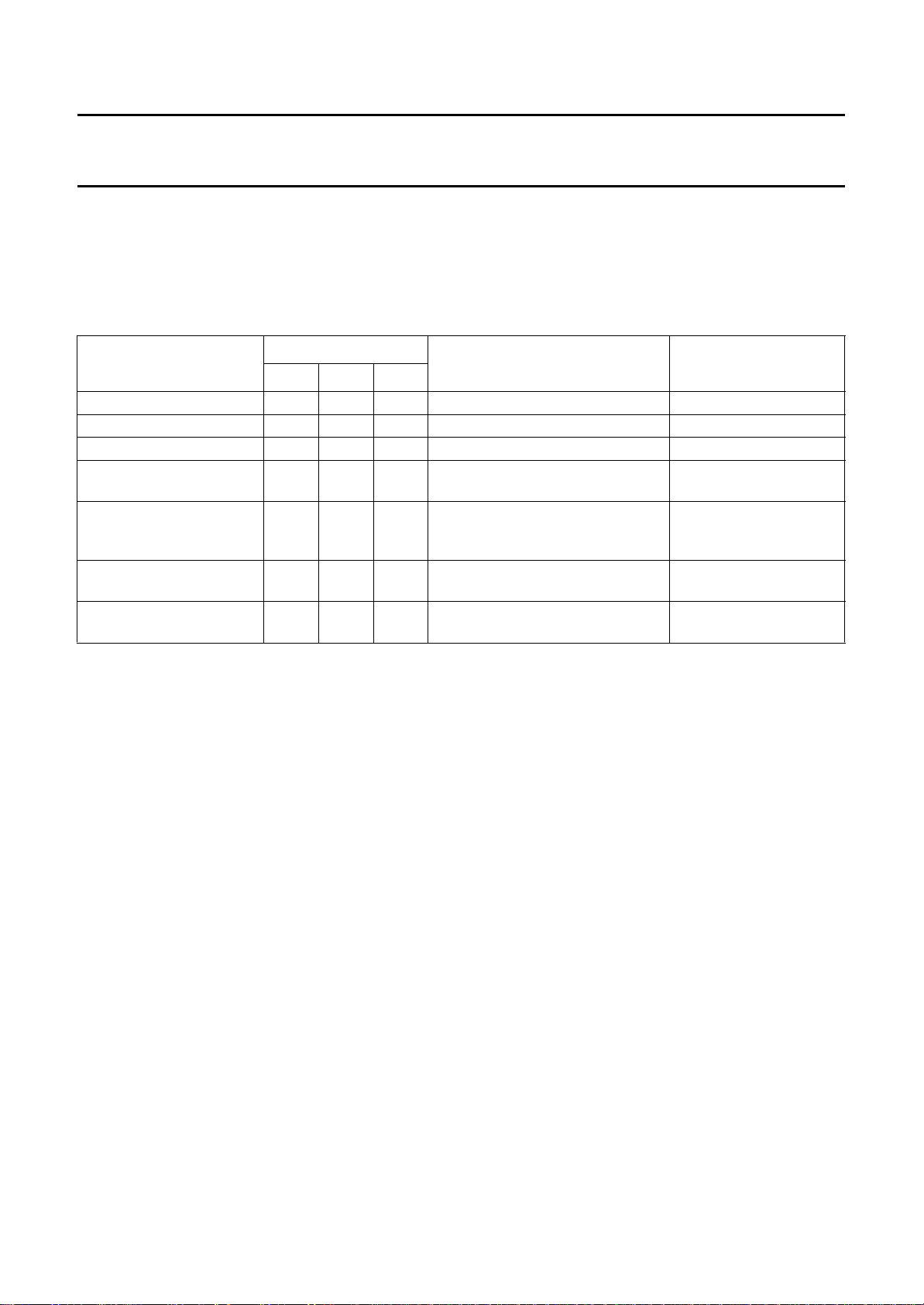
(see Table 2). In the reference sense current mode, only
one source is active (DSEN1B, pin 6). This current can be
used for temperature measurement of the DCC head,
thereby enabling control of the write current (TDA1381)
Equalization amplifiers
Two uncommitted operational amplifiers are available for
pre-equalization of the left and right ACC outputs. These
amplifiers are only operational during ACC playback. The
non-inverting input is internally connected to a DC voltage
which is approximately equal to V
If the amplifiers are
ref.
not used in the application, it is advised to connect the
outputs to the inputs.
when recording. The principle of the sense current sources
is illustrated in Fig.8. The typical value of the output current
is determined by resistors connected between the adjust
pins and V
; where I
SS
The DC output voltages V
V
are derived from an internal bandgap reference
refSENB
voltage source. The voltage V
DSEN
= 0.33/R
, V
ADC
refADC
.
ADJUST
, V10, V
ref
refSENA
(referenced to VSS)
and
can be used as a reference voltage for analog-to-digital
conversion of the RDMUX output.
Table 2 Sense current sources.
MODE
DIGITAL INPUTS
CS SA AB
(1)
AVAILABLE SENSE
CURRENT
ACTIVE DC OUTPUTS
Standby 0 1 0 −−
Reference sense current 0 0 X DSEN1B −
Sense AB 0 1 1 DSEN1A; DSEN2A; DSEN3A
DSEN1B; DSEN2B; DSEN3B
ACC playback A 1 1 1 DSEN1A; DSEN2A; DSEN3A V
ACC playback B 1 1 0 DSEN1B; DSEN2B; DSEN3B V
DCC playback A 1 0 1 DSEN1A; DSEN2A; DSEN3A V
DCC playback B 1 0 0 DSEN1B; DSEN2B; DSEN3B V
V
refSENA
V
refSENB
refSENA
refSENB
refSENA
refSENB
Note
1. Where X = don't care; 0 = LOW; 1 = HIGH.
September 1994 8
Page 9
Philips Semiconductors Preliminary specification
DCC read amplifier (READ 3) TDA1380
Modes of operation
The amplifiers and sense current sources for the ACC and DCC parts can be switched ON/OFF separately by the mode
switch signals CS, SA and AB. Also, a connection between OUTLB or OUTRB or both to VDD is recognized as a single
output ACC mode where the left and right outputs are present at OUTLA and OUTRA only.
Table 3 Modes of operation.
MODE
DIGITAL INPUT
CS SA AB
Standby 0 1 0
Reference sense current 0 0 X reference sense current source V
Sense AB 0 1 1 sense current sources V
ACC playback A/B 1 1 1 or 0 sense currents, data preamplifiers,
ACC playback A/B via
1 1 1 or 0 sense currents, data preamplifiers,
OUTLA and OUTRA only
(note 2)
DCC playback A/B 1 0 1 or 0 sense currents, data amplifiers and
Test mode (note 3) 1 0 1 or 0 sense currents, data amplifiers and
(1)
ACTIVE PARTS
(see Fig.1)
AN, EQ and FB
AN, EQ and FB
filters, multiplexer, AGC and FB
filters, multiplexer, AGC and FB
ACTIVE DC
REFERENCE OUTPUTS
ref
ref
V
; V10
ref
V
; V10
ref
; V10; V
V
ref
V
ref
; V10; V
refADC
refADC
Notes
1. Where X = don't care; 0 = LOW; 1 = HIGH.
2. At least one of OUTLB or OUTRB are externally connected to V
3. INEQL or INEQR connected to VDD (no user function).
DD
.
September 1994 9
Page 10
Philips Semiconductors Preliminary specification
DCC read amplifier (READ 3) TDA1380
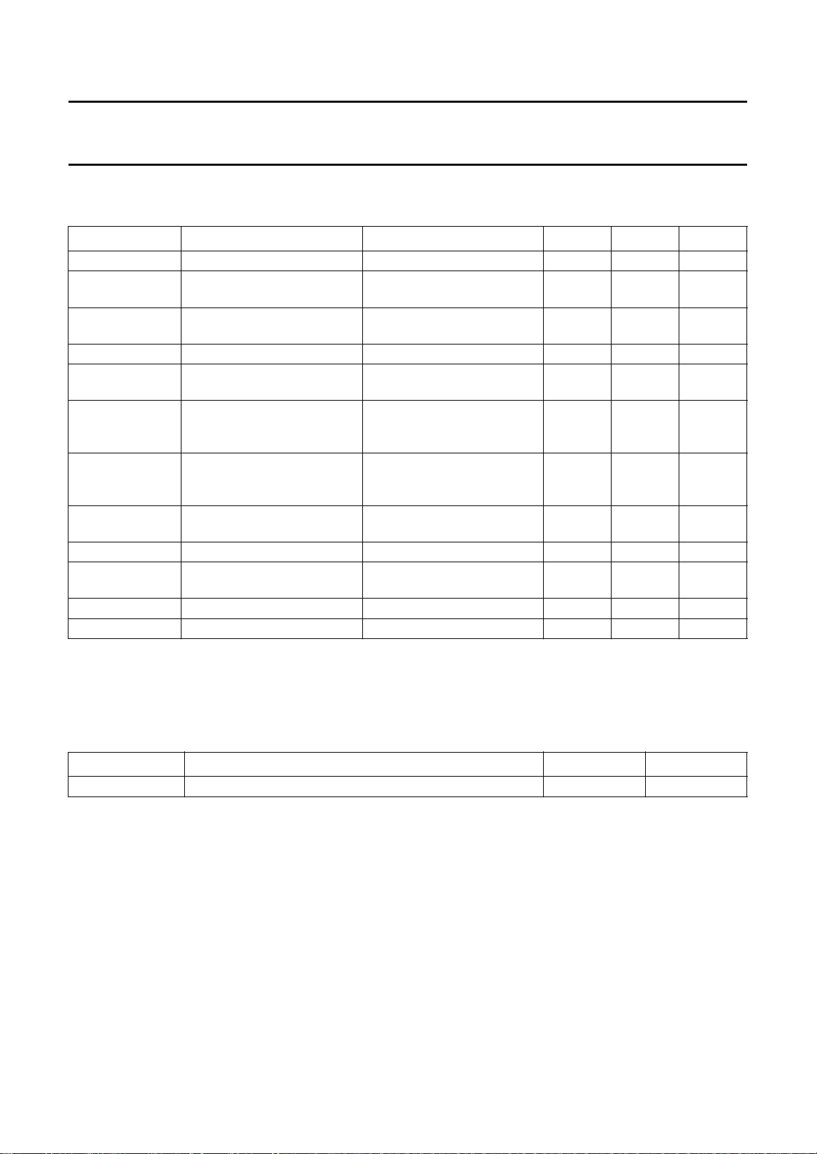
LIMITING VALUES
In accordance with the Absolute Maximum Rating System (IEC 134); voltages referenced to V
SYMBOL PARAMETER CONDITIONS MIN. MAX. UNIT
V
V
DD
CCM
supply voltage VSS=V
supply voltage feedback
VSS=V
=0V −0.3 5.5 V
EEM
=0V −0.3 5.5 V
EEM
amplifiers
V
SS−VEEM
difference in ground potential
00V
between pins 57 and 42
V
I
I
I(max)
voltage input on any pin VDD+ 0.3 < 5.5 V −0.3 VDD+ 0.3 V
maximum supply current
−±120 mA
(pins 41, 42, 57 and 58)
I
FBmax
maximum current for
−±80 mA
feedback amplifiers (pins 33
to 35 and 48 to 50)
I
sense(max)
maximum current on sense
−±30 mA
current source (pins 1 to 3
and 6 to 11)
I
n(max)
maximum current on any
−±10 mA
other pin
P
tot
T
amb
total power dissipation − 650 mW
operating ambient
−30 +85 °C
temperature
T
stg
V
es
storage temperature −65 +50 °C
electrostatic handling −3000 +3000 V
and V
SS
EEM
.
ELECTROSTATIC HANDLING
Equivalent to discharging a 100 pF capacitor through a 1.5 kΩ series resistor.
THERMAL CHARACTERISTICS
SYMBOL PARAMETER VALUE UNIT
R
th j-a
thermal resistance from junction to ambient in free air 60 K/W
September 1994 10
Page 11
Philips Semiconductors Preliminary specification
DCC read amplifier (READ 3) TDA1380
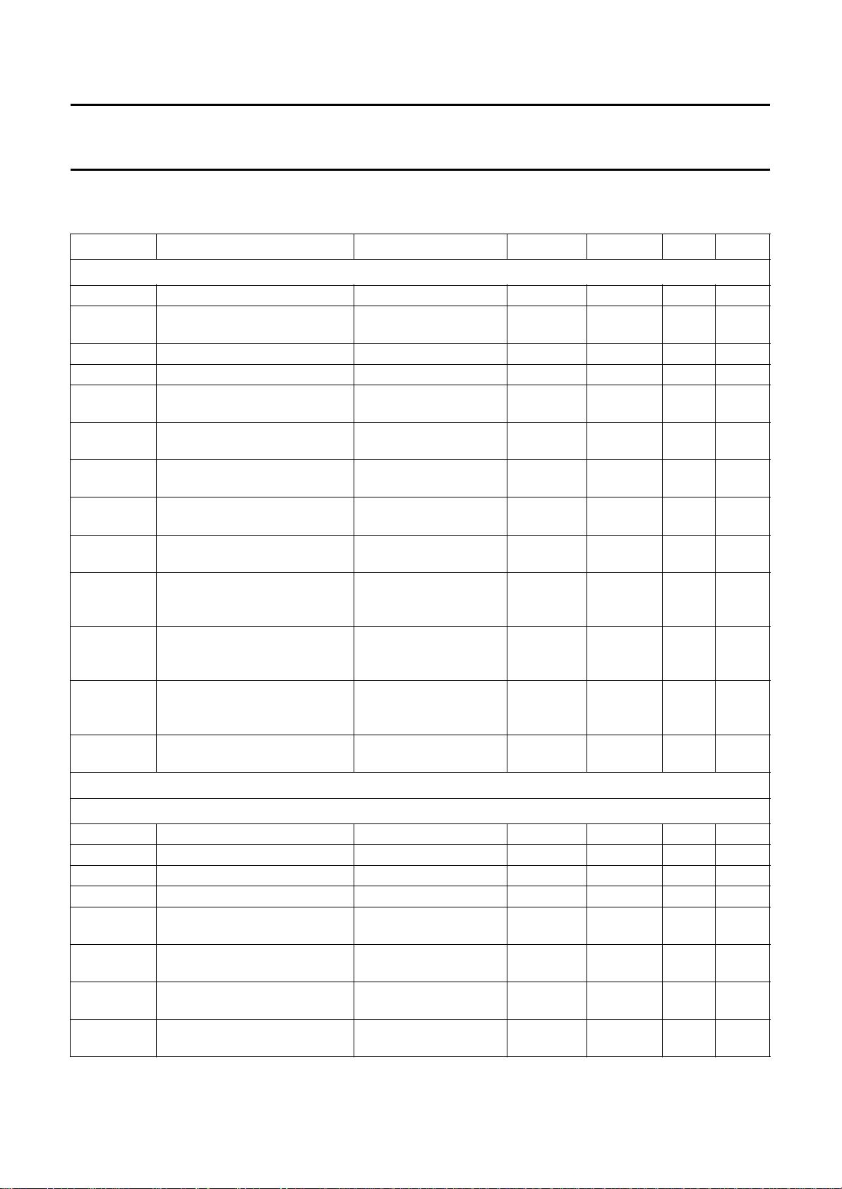
CHARACTERISTICS
VDD= V
SYMBOL PARAMETER CONDITIONS MIN. TYP. MAX. UNIT
Supply
V
DD
V
CCM
I
DDDCC
I
DDACC
I
DDRS
I
DDAB
I
CCM
I
DDstb+ICCM
V
refADC
V
refSENA
V
refSENB
V
ref
V10 reference voltage for DCC
= 3 V; VSS=V
CCM
supply voltage 2.7 3.0 5.5 V
supply voltage feedback
amplifiers
supply current DCC mode CS = 1; SA = 0 18 27 37 mA
supply current ACC mode CS = 1; SA = 1 16 23 30 mA
supply current reference sense
current mode
supply current sense AB mode CS = 0; SA = 1;
supply current feedback
amplifiers
supply current standby mode CS = 0; AB = 0;
reference voltage for ADC CS = 1; SA = 0;
sense A reference voltage CS = 1; AB = 1;
sense B reference voltage CS = 1; AB = 0;
reference voltage output IO<5µA;
inputs
EEM
=0V; T
amb
=25°C; f
= 3.072 MHz; unless otherwise specified.
clk
2.7 3.0 5.5 V
CS = 0; SA = 0 0.6 1.2 1.6 mA
1.5 2.7 3.7 mA
AB = 1
CS = 1 7.5 12 17.5 mA
− 0.2 0.3 mA
SA = 1
1.95 2.05 2.15 V
RL=1kΩ
1.0 1.1 1.2 V
IO<5µA;
I
= 10 mA
DSEN
1.0 1.1 1.2 V
IO<5µA;
I
= 10 mA
DSEN
1.18 1.25 1.32 V
all modes except
standby mode
CS = 1; I
<5µA 0.9 1.0 1.1 V
O
DCC part
ATA AMPLIFIERS, CHANNELS 0 TO 7; NOTE 1
D
G
50
∆G
10
G
100
∆G
300
V
n(ref)
∆V
n(ref)
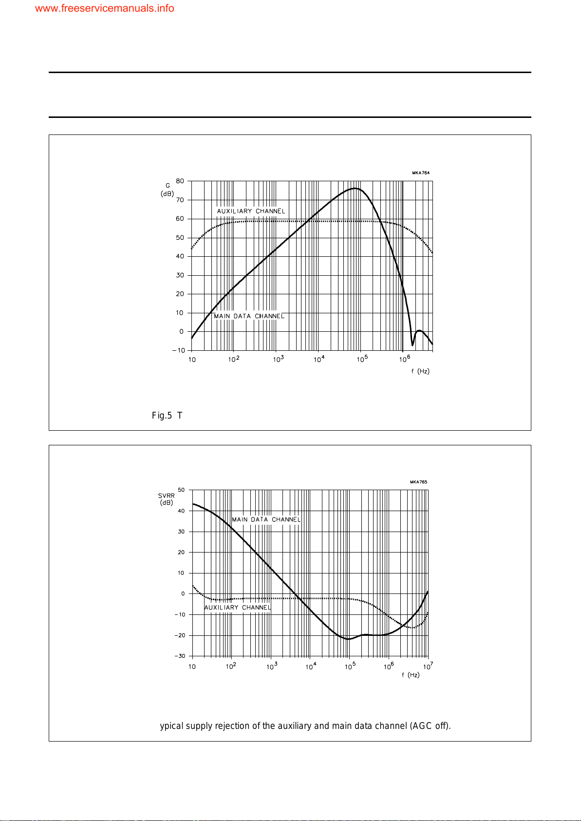
gain at 50 kHz 72 75 78 dB
relative gain at 10 kHz note 2 −14 −12 −10 dB
gain at 100 kHz 71 76 79 dB
relative gain at 300 kHz note 2 −22 −12 −3dB
input referred noise voltage fi= 50 kHz;
3 × standard deviation of input
referred noise voltage
THD total harmonic distortion f
Z
i(d)
input impedance differential
mode
September 1994 11
R
source
=70Ω
fi= 50 kHz;
R
=70Ω
source
= 10 kHz;
i
V62= 0.35 V (RMS)
− 2.0 − nV/√Hz
− 0.5 − nV/√Hz
−−40 −30 dB
− 7 − kΩ
Page 12
Philips Semiconductors Preliminary specification
DCC read amplifier (READ 3) TDA1380
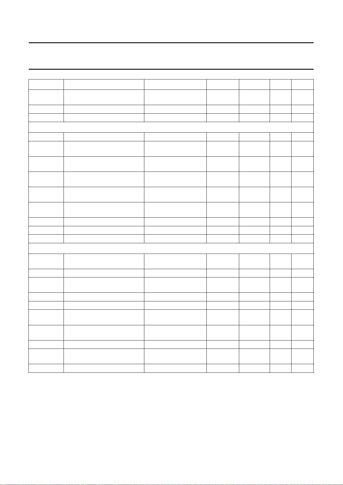
SYMBOL PARAMETER CONDITIONS MIN. TYP. MAX. UNIT
Z
i(c)
α
cs
SVRR supply voltage ripple rejection f
Auxiliary amplifier, channel X; note 1
G
63
G
62
V
n(ref)
∆V
n(ref)
V
o(rms)
THD total harmonic distortion f
SVRR supply voltage ripple rejection f
R
L(DC)
C
L(AC)
Output buffer, RDMUX (pin 62)
V
62(rms)
V
DC
∆V
DC(os)
R
L(DC)
C
L(AC)
t
set
V
62(M)
AGC
CR
I
source
I
sink
input impedance to V
SS
− 7.5 − kΩ
common mode
channel separation fi= 10 kHz 30 40 − dB
= 50 kHz; note 3 −−20 − dB
i
gain at OUTX (pin 63) 100 Hz to 100 kHz 43 46 49 dB
gain at RDMUX (pin 62) 100 Hz to 100 kHz;
56 59 62 dB
note 4
input referred noise voltage fi= 50 kHz;
3 x standard deviation input
referred noise voltage
maximum output voltage (pin
R
fi= 50 kHz;
R
fi= 10 kHz 0.35 −−V
source
source
=70Ω
=70Ω
− 2.0 − nV/√Hz
− 0.5 − nV/√Hz
63) (RMS value)
= 10 kHz;
i
−−40 −30 dB
V63= 0.35 V (RMS)
= 1 kHz; note 3 −−3−dB
i
DC load at pin 63 load connected to V
AC load at pin 63 load connected to V
maximum output voltage (RMS
RL=2kΩ 0.35 −−V
10 −−kΩ
SS
−−100 pF
SS
value)
DC voltage level at pin 62 0.95 1.15 1.35 V
DC offset voltage between
note 5 −−200 mV
sampled outputs
DC load at pin 62 load connected to V
AC load at pin 62 load connected to V
settling time of sampled outputs CL= 50 pF;
1.5 −−kΩ
SS
−−100 pF
SS
− 100 150 ns
within 10 mV
AGC detector level
note 5 320 465 570 mV
(peak value)
AGC control range 9 11 13 dB
AGC source current
16 21 26 µA
(pin 60)
AGC sink current (pin 60) 0.3 0.5 0.8 µA
September 1994 12
Page 13
Philips Semiconductors Preliminary specification
DCC read amplifier (READ 3) TDA1380
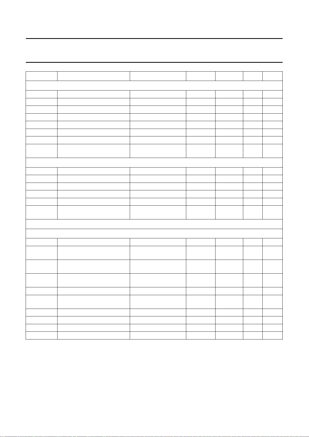
SYMBOL P ARAMETER CONDITIONS MIN. TYP. MAX. UNIT
Select logic inputs (RDCLK and RDSYNC) and mode switch inputs (CS, SA and AB)
V
IH
V
IL
I
IL
C
i
t
su
t
h
t
r
V
det
HIGH level input voltage 0.7V
LOW level input voltage 0 − 0.3VDDV
input leakage current −20 +2µA
input capacitance note 7 −−10 pF
set-up time for RDSYNC see Fig.3 35 −−ns
hold time for RDSYNC see Fig.3 35 −−ns
rise time for RDCLK see Fig.3 −−50 ns
ACC single output mode
detection level (pins 38 and 45)
Sense current sources
I
DSENmin
I
DSENmax
I
DSEN1B
I
ON
Z
DSEN
V
DSEN
minimum output current note 8 −−1mA
maximum output current note 8 20 −−mA
reference sense current (pin 6) note 9 2.7 3.0 3.3 mA
output current noise note 10 − 20 − pA/√Hz
output impedance note 10 20 −−kΩ
DC voltage level of current
outputs (pins 6 to 11)
DD
VDD− 0.45 VDD− 0.35 − V
1.0 −−V
− V
DD
V
ACC part
AMPLIFIERS
ACC
G
V
∆V
ACC
n(ref)
n(ref)
ACC gain 20 Hz to 20 kHz 44 46 48 dB
input referred noise voltage fi= 10 kHz;
3 x standard deviation of input
referred noise voltage
V
o(rms)
maximum output voltage (RMS
value)
V
A
DC output voltage see Table 1 0.6 0.9 1.2 V
THD total harmonic distortion f
SVRR supply voltage ripple rejection f
α
cs
R
L(DC)
C
L(AC)
channel separation fi= 1 kHz 40 −−dB
DC load (pins 37, 38 45 and 46) load connected to V
AC load (pins 37, 38 45 and 46) load connected to V
− 2.0 − nV/√Hz
R
f = 10 kHz;
R
source
source
=70Ω
− 0.5 − nV/√Hz
=70Ω
fi= 1 kHz 0.35 −−V
= 1 kHz;
i
−−40 −30 dB
Vo= 0.35 V (RMS)
= 1 kHz − tbf − dB
i
10 −−kΩ
SS
−−300 pF
SS
September 1994 13
Page 14
Philips Semiconductors Preliminary specification
DCC read amplifier (READ 3) TDA1380
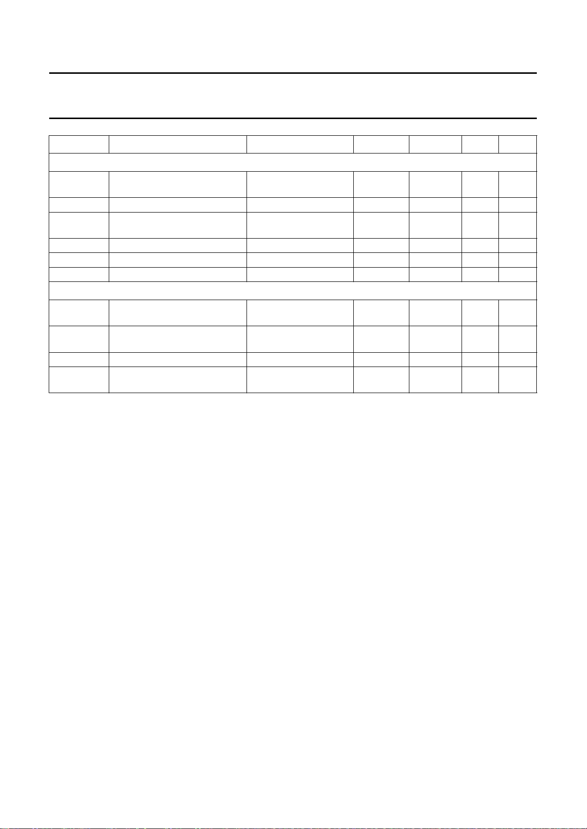
SYMBOL PARAMETER CONDITIONS MIN. TYP. MAX. UNIT
Equalization operational amplifiers (EQ); note 11
V
EQ(rms)
maximum output voltage (RMS
value)
B
EQ
bandwidth at −3dB 50 −−kHz
THD total harmonic distortion f
α
cs
R
L(DC)
C
L(AC)
channel separation fi= 1 kHz 60 −−dB
DC load at OUTEQL load connected to V
AC load at OUTEQL load connected to V
Feedback amplifiers (FB); note 12
I
FBmax
maximum output current (RMS
value)
THD total harmonic distortion f
B
FB
V
IFB
bandwidth at −3dB 50 −−kHz
DC voltage level input (pins 36
and 47)
fi= 1 kHz 0.35 −−V
= 1 kHz;
i
−−70 −55 dB
VO= 0.35 V (RMS)
10 −−kΩ
SS
−−300 pF
SS
fi= 1 kHz 25 −−mA
= 1 kHz;
i
−−60 −50 dB
IFB= 25 mA (RMS)
− 1.15 − V
Notes
1. AGC off (maximum gain; pin 60 connected to VSS).
2. Gain relative to gain at fi= 50 kHz (see Fig.5).
3. Heads connected according to the circuit of Fig.11 (see also Fig.6 for typical supply rejection).
4. OUTX AC-coupled to MUXINX via 100 nF capacitor.
5. The difference between minimum and maximum DC voltage level at the outputs of the data channels. To be
measured at RDMUX.
6. Measured with continuous sine wave of 10 kHz at RDMUX, multiplexer in a fixed position.
A 1 V (p-p) sine wave corresponds to a multiplexed DCC signal of 1.25 V (p-p).
7. Periodically sampled, not tested.
8. Pins 6 to 11. The output current is inversely proportional to the value of the resistor connected between the adjust
pin DSENADJ1, DSENADJ2, DSENADJ3 and VSS. A resistor of 33 Ω will give 10 mA (typ.) sense current. Other
currents can be calculated: 0.33 V/R
ADJUST
.
9. CS = 0, SA = 0; Resistor of 33 Ω connected between DSENADJ1 and VSS. Typical reference sense current is
100 mV/R
10. From 10 to 100 kHz, IDSEN = 10 mA, a 10 µF capacitor connected between V
connected between V
ADJUST
.
and VSS, a 10 µF capacitor
refSENA
and VSS.
refSENB
11. Closed loop configuration, unity gain, in accordance with Fig.10.
12. Closed loop, unity gain, RL=25Ω, in accordance with Fig.9.
September 1994 14
Page 15
Philips Semiconductors Preliminary specification
DCC read amplifier (READ 3) TDA1380
Fig.3 Timing relationship between edges of RDCLK and RDSYNC.
September 1994 15
Fig.4 Multiplexer timing diagram.
Page 16
Philips Semiconductors Preliminary specification
BBBB
BBBB
BBBBBBBBBBBBBBBBBBBBBBB
B
B
B
B
B
B
B
B
B
B
B
B
B
B
B
B
BBBBBBBBBBBBBBBBBBBBBBB
BBBB
BBBB
BBBB
DCC read amplifier (READ 3) TDA1380
Fig.5 Typical gain of the auxiliary and main data channel (AGC off).
BBBBBBBBBBBBBBBBBBBBBB
BBBBBBBBBBBBBBBBBBBBBB
BBBBBBBBBBBBBBBBBBBBBB
BBBBBBBBBBBBBBBBBBBBBB
BBBBBBBBBBBBBBBBBBBBBB
BBBBBBBBBBBBBBBBBBBBBB
BBBBBBBBBBBBBBBBBBBBBB
BBBBBBBBBBBBBBBBBBBBBB
BBBBBBBBBBBBBBBBBBBBBB
BBBBBBBBBBBBBBBBBBBBBB
BBBBBBBBBBBBBBBBBBBBBB
BBBBBBBBBBBBBBBBBBBBBB
BBBBBBBBBBBBBBBBBBBBBB
BBBBBBBBBBBBBBBBBBBBBB
BBBBBBBBBBBBBBBBBBBBBB
BBBBBBBBBBBBBBBBBBBBBB
Fig.6 Typical supply rejection of the auxiliary and main data channel (AGC off).
September 1994 16
Page 17
Philips Semiconductors Preliminary specification
DCC read amplifier (READ 3) TDA1380
TEST AND APPLICATION INFORMATION
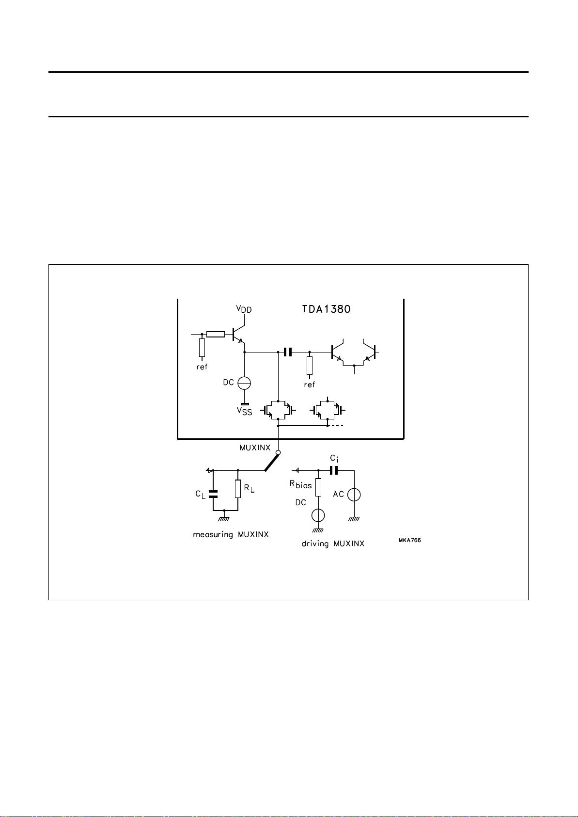
The TDA1380 can be set to the TEST mode by connecting
INEQL or INEQR (or both) to VDD. In this mode the switch
at pin MUXINX enables monitoring of the input stage and
lowpass filter of each data amplifier and also allows input
to the highpass filters and following stages. The test
multiplexer operates in phase with the output multiplexer.
Measurement of the gain of the data channels can be
performed in two steps: step 1, gain from the inputs to
MUXINX; step 2, gain from MUXINX to RDMUX.
Figure 7 illustrates how to use pin MUXINX in the TEST
mode, C
R
bias
should be 0.7 V higher than the measured DC level of the
preamplifier output in order to shut off the emitter follower.
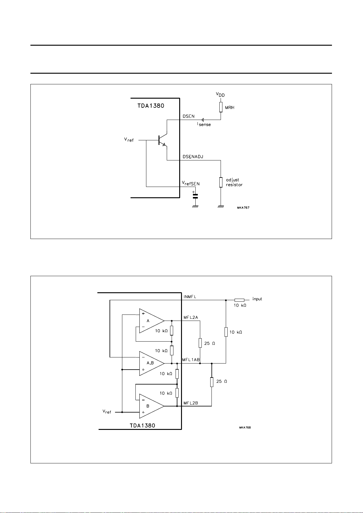
The impedance of the sense current source outputs can be
measured from the difference in sense current when
applying different voltages to the sense current output.
This voltage can vary from 1 V to VDD. Figure 8 illustrates
the principle of the sense current sources.
< 20 pF, RL> 100 kΩ, Ci> 47 nF and
L
=1kΩ. The DC voltage, when driving MUXINX,
September 1994 17
Fig.7 Use of the MUXINX pin in the TEST mode.
Page 18
Philips Semiconductors Preliminary specification
DCC read amplifier (READ 3) TDA1380
Fig.8 Principle of the sense current sources.
The feedback amplifiers consist of three operational amplifiers providing one input and a differential output with respect
to an internal 1.15 V reference. The active output A or B is selected by the tape sector selection signal AB.
September 1994 18
Fig.9 Principle of the feedback amplifiers and TEST circuit.
Page 19
Philips Semiconductors Preliminary specification
DCC read amplifier (READ 3) TDA1380
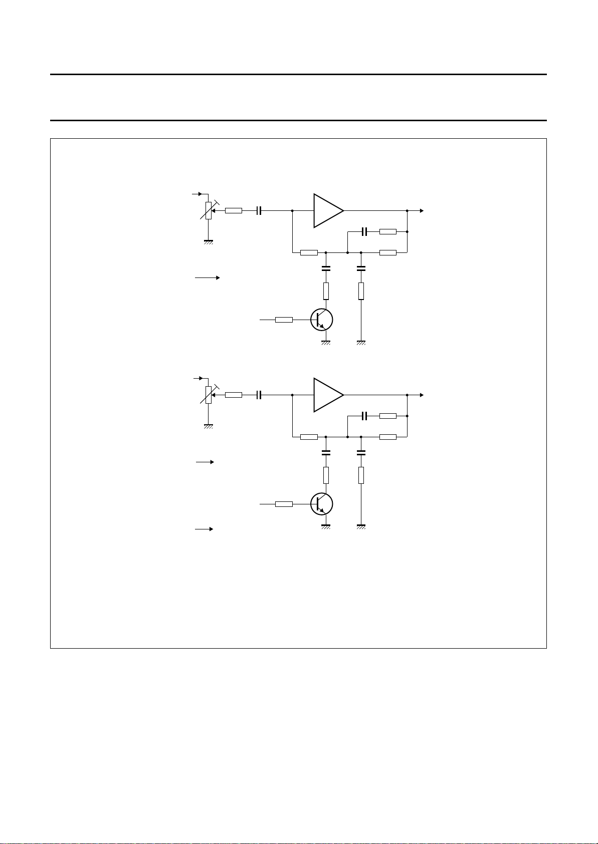
Fig.10 Test circuit of the equalization amplifiers.
September 1994 19
Fig.11 Connection of the TDA1380 to the MRH (partial).
Page 20
Philips Semiconductors Preliminary specification
DCC read amplifier (READ 3) TDA1380
handbook, full pagewidth
OUTL
INEQL
OUTR
INEQR
ME FE
10 kΩ
10 kΩ
22 kΩ
DOLBY
level
left A
22 kΩ
DOLBY
level
right A
(2)
INEQL
330 nF
ME FE
(2)
INEQR
(1)
330 nF
METAL / FERRO
CORRECTION
ME FE
(1)
10 kΩ
10 kΩ
44
15 kΩ
BC848
39
15 kΩ
BC848
AN EQ AMP
LEFT
(internal)
(3)
7.5
nF
2 kΩ
AN EQ AMP
RIGHT
(internal)
(3)
7.5
nF
2 kΩ
43
(1)
40
(1)
12 nF
(1)
12 nF
(1)
18 kΩ
(3)
150 kΩ
6.8
nF
1.8 kΩ
18 kΩ
(3)
150 kΩ
6.8
nF
1.8 kΩ
MGA965
OUTEQL
(3)
(3)
(3)
(1)
OUTEQR
(3)
(3)
(3)
(1)
Frequency compensation values are totally dependent on head frequency response characteristics.
(1) Less than 10%.
(2) Less than 5%.
(3) Less than 2%.
September 1994 20
Fig.12 Analog equalizer.
Page 21
Philips Semiconductors Preliminary specification
h
DCC read amplifier (READ 3) TDA1380
2.7 to 4.0 V
(4x)
nF
100
47 kΩ
V
V
V
V
67 11 23 41 52 61 72 69 32
BIAS
V
100
nF
87 mA (typ.)
2.7 to 5.5 V
1
SBWS
DDR
V
DDA
DD6
V
DD5
DD4
V
DD3
DD2
V
DD1
RDMUX71RDSYNC59TCLOCK64V65V
63
120 Ω
2
3
SBCL
80
SBDA
ref(p)
to
100
SFC
SBEF
ref(n)
nF
82 pF
4
SBDIR
6
5
URDA
SBMCLK
ANAEYE58WDATA
70
test point
amp
WR
to
microcontroller
7
9
15
PWRDWN
L3DATA
L3MODE
8
13
L3CLK
10
L3REF
L3INT
17
AZCHK
19
20
PRGSTAT
ERCOSTAT
14
RESET
SAA2023
CHTST175CHTST2
34D031D130D229D328D427D526D625D735A036A137A238A339A442A543A644A751A854
74
to DOLBY
circuitry
left
ANALOG
EQUALIZER
point
virtual ground
24.576 MHz
18
16
F24
RAM
speed control
57
56
MCLK
SPEED
A9/CAS22A10/RAS55A1145A1250A1346A1448A1547A16
I/O
optional
PINO079PINO1
to DOLBY
circuitry
right
78
PINI
76
TEST077TEST162TEST2
ANALOG
EQUALIZER
MGA967
66
SSR
V
SSA
V
SS6
V
SS5
V
SS4
V
SS3
V
SS2
V
12 24 40 53 60 73 68 33
SS1
V
OEN
WEN
21
49
andbook, full pagewidth
GROUNDS are directly connected
left
level
DOLBY
45
4749485044
INMFL
OUTLB
IN56A
IN67A
IN7A
242322
MFL1AB
DSEN3A
9
NOISE
DECOUPLER
to
10 µH
R 1.7 Ω
CA
AMY HEAD
nF
100
64625554595653
63
10
µF
OUTX
RDCLK
RDMUX
100
nF
10
µF
10
µF
100
nF
CB
MUXINX
CCM
V
58 4132
DD
V10 V
INX25A
INX0A
IN01A
IN1A
313029
28
CS
RDSYNC
DSEN1A
11
27
SA
IN23A
to
AB
IN34A
26
A
HEAD
52
25
refADC
V
IN4A
46
OUTLA
DSEN2A
10
September 1994 21
43
INEQL
MFL2B
MFL2A
OUTEQL
TDA1380
INX25B
INX0B
IN01B
IN1B
DSEN1B
1213146161718
15
to
WR3
37
OUTRA38OUTRB
IN23B
to
IN34B
B
HEAD
level
DOLBY
363435
INMFR
MFR1AB
IN4B
DSEN2B
7
right
333940
MFR2A
IN56B
192021
MFR2B
IN67B
IN7B
INEQR
DSEN3B
8
AGC
OUTEQR
VBIAS
ref
V
SS
V
EEM
V
refSENB
V
refSENA
V
DSENADJ3
DSENADJ2
DSENADJ1
ref
V
51 61 60
42
5
4
123 57
LOAD 5 µA!!
OUTPUT
1
1
10
10
10
33
33
33
µF
µF
µF
µF
µF
Ω
Ω
Ω
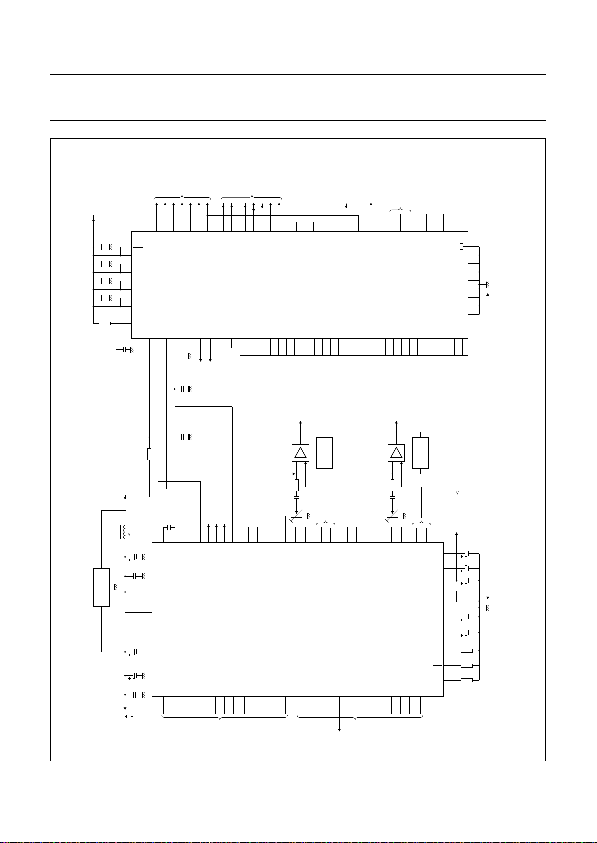
Fig.13 TDA1380 and SAA2023 interconnection diagram.
Page 22
Philips Semiconductors Preliminary specification
DCC read amplifier (READ 3) TDA1380
andbook, full pagewidth
X
0
1
L
2
3
4
5
R
6
7
X
0
1
L
2
3
4
5
R
6
7
FLEX
TA4
TA4
CA
AX0
A01
A1
A23
A34
A4
A56
A67
A7
TA3
TA3
TB1
TB1
CB
BX0
B01
B1
B23
B34
B4
B56
B67
B7
TB2
TB2
10 µH
Ω
R
2.5
in
10µF100
1 µF
1 µF
1 µF
1 µF
1 µF
1 µF
nF
1 µF
1 µF
1 µF
1 µF
1 µF
1 µF
1 µF
1 µF
1 µF
1 µF
1 µF
1 µF
1 µF
1 µF
28
31
30
29
11
27
26
25
10
24
23
22
9
15
12
13
14
6
16
17
18
7
19
20
21
8
10
µF
V10 V
INX25A
INX0A
IN01A
IN1A
DSEN1A
IN23A
IN34A
IN4A
DSEN2A
IN56A
IN67A
IN7A
DSEN3A
INX25B
INX0B
IN01B
IN1B
DSEN1B
IN23B
IN34B
IN4B
DSEN2B
IN56B
IN67B
IN7B
DSEN3B
DSENADJ2
DSENADJ1
12 3 57
33
Ω
SENSE CURRENT
setting
100 kΩ
100 kΩ
10
nF
10
nF
10
nF
10
nF
10
nF
10
nF
10
nF
10
nF
10
nF
10
nF
10
nF
10
nF
10
nF
10
nF
10
nF
10
nF
10
nF
10
nF
58 4132
DD
V
DSENADJ3
33Ω33
Ω
to WRITE3
TDA1381
for write
current correction
10 µH
1.7 Ω
R
in
POWER
DECOUPLING
V
100
nF
TDA1380
READ
AMPLIFIER 3
refSENA
V
refSENB
4
10
µF
10 µH
1.7 Ω
R
in
V
V
42
CCM
V
SS
10
µF
100
nF
ref
VBIAS
51 61 60
MUXINX
RDMUX
RDSYNC
V
MFL1AB
OUTEQL
OUTRA
OUTRB
MFR1AB
OUTEQR
1
µF
10
µF
V
EEM
5
10
µF
OUTX
RDCLK
refADC
OUTLA
OUTLB
INMFL
MFL2A
MFL2B
INEQL
INMFR
MFR2A
MFR2B
INEQR
AGC
2.7 to 5.5 V
10
µF
63
100
64
nF
62
55
54
59
CS
56
SA
53
AB
52
100 kΩ
46
V
OUTL
OUTR
ref
V
100 kΩ
V
220 nF
560 kΩ
1 nF
1 nF
220 nF
560 kΩ
1 nF
1 nF
OUTL
INEQL
OUTR
INEQR
ME FE
45
47
49
48
50
44
43
37
38
36
34
35
33
39
40
1
µF
RDSYNC
V
1 MΩ
10 Ω
1 MΩ
10 Ω
ANALOG
EQUALIZATION
SEE FIG.11
V
CS
SA
AB
ME FE
RDMUX
RDCLK
refADC
VBIAS
SETTING
TB1
FEEDBACK
LEVEL
HEAD
V
AMP
TA4TB1
TA4
TA3TB2
TA3
TB2
OUTEQL
OUTEQL
MGA966
to power
2.7 to 5.5 V
microcontroller
0 V
to DRP
V
ref
LEFT
CORRECTION
DOLBY IC
RIGHT
CORRECTION
to
AMP
to
Power V
and power V
HEAD
With respect to power consumption:
(1) V
(2) V
(3) START-UP I
; 3 ×I
HEAD
AMP
sense
; ≤42 mA at 3 V.
× V
; 150 mA at V
peak
September 1994 22
have to be very clean in the frequency range 0 to 1 kHz.
AMP
.
HEAD
.
HEAD
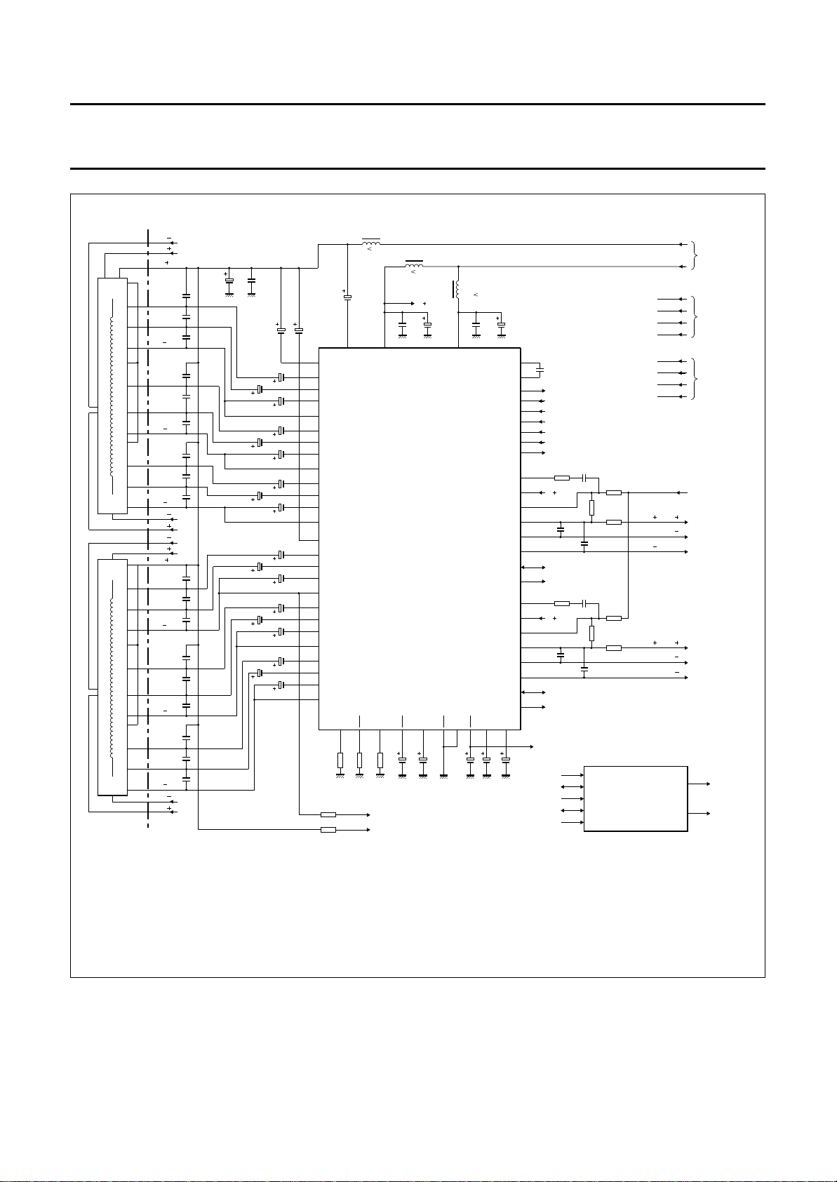
Fig.14 Application diagram.
Page 23
Philips Semiconductors Preliminary specification
DCC read amplifier (READ 3) TDA1380
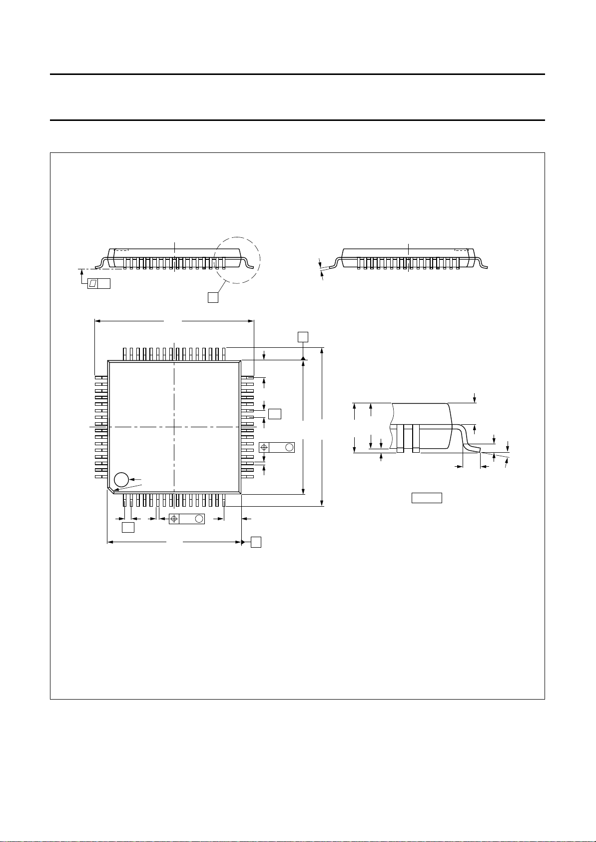
PACKAGE OUTLINE
handbook, full pagewidth
0.18
0.1
X
12.3
11.7
0.12
B
48 33
49
pin 1
64
index
1
0.12 M
0.27
0.5
0.17
10.1
9.9
16
1.45
1.05
1.45
32
1.05
0.5
10.1
12.3
9.9
11.7
0.12 M
0.27
0.17
17
A
1.60
1.35
1.45
1.35
0.20
0.05
detail X
0.69
0.59
0.75
0.50
(0.25)
0 to 7
MSA411
o
Dimensions in mm.
Fig.15 plastic thin quad flat package; 64 leads; body 10 × 10 × 1.4 mm (TQFP64; SOT314-2).
September 1994 23
Page 24

Philips Semiconductors Preliminary specification
DCC read amplifier (READ 3) TDA1380
SOLDERING
Plastic quad flat-packs
YWAVE
B
During placement and before soldering, the component
must be fixed with a droplet of adhesive. After curing the
adhesive, the component can be soldered. The adhesive
can be applied by screen printing, pin transfer or syringe
dispensing.
Maximum permissible solder temperature is 260 °C, and
maximum duration of package immersion in solder bath is
10 s, if allowed to cool to less than 150 °C within 6 s.
Typical dwell time is 4 s at 250 °C.
A modified wave soldering technique is recommended
using two solder waves (dual-wave), in which a turbulent
wave with high upward pressure is followed by a smooth
laminar wave. Using a mildly-activated flux eliminates the
need for removal of corrosive residues in most
applications.
Y SOLDER PASTE REFLOW
B
Reflow soldering requires the solder paste (a suspension
of fine solder particles, flux and binding agent) to be
applied to the substrate by screen printing, stencilling or
pressure-syringe dispensing before device placement.
EPAIRING SOLDERED JOINTS (BY HAND-HELD SOLDERING
R
IRON OR PULSE
-HEATED SOLDER TOOL)
Fix the component by first soldering two, diagonally
opposite, end pins. Apply the heating tool to the flat part of
the pin only. Contact time must be limited to 10 s at up to
300 °C. When using proper tools, all other pins can be
soldered in one operation within 2 to 5 s at between 270
and 320 °C. (Pulse-heated soldering is not recommended
for SO packages.)
For pulse-heated solder tool (resistance) soldering of VSO
packages, solder is applied to the substrate by dipping or
by an extra thick tin/lead plating before package
placement.
Several techniques exist for reflowing; for example,
thermal conduction by heated belt, infrared, and
vapour-phase reflow. Dwell times vary between 50 and
300 s according to method. Typical reflow temperatures
range from 215 to 250 °C.
Preheating is necessary to dry the paste and evaporate
the binding agent. Preheating duration: 45 min at 45 °C.
September 1994 24
Page 25
Philips Semiconductors Preliminary specification
DCC read amplifier (READ 3) TDA1380
DEFINITIONS
Data sheet status
Objective specification This data sheet contains target or goal specifications for product development.
Preliminary specification This data sheet contains preliminary data; supplementary data may be published later.
Product specification This data sheet contains final product specifications.
Limiting values
Limiting values given are in accordance with the Absolute Maximum Rating System (IEC 134). Stress above one or
more of the limiting values may cause permanent damage to the device. These are stress ratings only and operation
of the device at these or at any other conditions above those given in the Characteristics sections of the specification
is not implied. Exposure to limiting values for extended periods may affect device reliability.
Application information
Where application information is given, it is advisory and does not form part of the specification.
LIFE SUPPORT APPLICATIONS
These products are not designed for use in life support appliances, devices, or systems where malfunction of these
products can reasonably be expected to result in personal injury. Philips customers using or selling these products for
use in such applications do so at their own risk and agree to fully indemnify Philips for any damages resulting from such
improper use or sale.
The Digital Compact Cassette logo is a registered trade mark of Philips Electronics N.V.
September 1994 25
Page 26

Philips Semiconductors Preliminary specification
DCC read amplifier (READ 3) TDA1380
NOTES
September 1994 26
Page 27

Philips Semiconductors Preliminary specification
DCC read amplifier (READ 3) TDA1380
NOTES
September 1994 27
Page 28

Philips Semiconductors – a worldwide company
Argentina: IEROD, Av. Juramento 1992 - 14.b, (1428)
BUENOS AIRES, Tel. (541)786 7633, Fax. (541)786 9367
Australia: 34 Waterloo Road, NORTH RYDE, NSW 2113,
Tel. (02)805 4455, Fax. (02)805 4466
Austria: Triester Str. 64, A-1101 WIEN, P.O. Box 213,
Tel. (01)60 101-1236, Fax. (01)60 101-1211
Belgium: Postbus 90050, 5600 PB EINDHOVEN, The Netherlands,
Tel. (31)40 783 749, Fax. (31)40 788 399
Brazil: Rua do Rocio 220 - 5
CEP: 04552-903-SÃO PAULO-SP, Brazil.
P.O. Box 7383 (01064-970).
Tel. (011)821-2333, Fax. (011)829-1849
Canada: PHILIPS SEMICONDUCTORS/COMPONENTS:
Tel. (800) 234-7381, Fax. (708) 296-8556
Chile: Av. Santa Maria 0760, SANTIAGO,
Tel. (02)773 816, Fax. (02)777 6730
Colombia: IPRELENSO LTDA, Carrera 21 No. 56-17,
77621 BOGOTA, Tel. (571)249 7624/(571)217 4609,
Fax. (571)217 4549
Denmark: Prags Boulevard 80, PB 1919, DK-2300 COPENHAGEN S,
Tel. (032)88 2636, Fax. (031)57 1949
Finland: Sinikalliontie 3, FIN-02630 ESPOO,
Tel. (9)0-50261, Fax. (9)0-520971
France: 4 Rue du Port-aux-Vins, BP317,
92156 SURESNES Cedex,
Tel. (01)4099 6161, Fax. (01)4099 6427
Germany: P.O. Box 10 63 23, 20043 HAMBURG,
Tel. (040)3296-0, Fax. (040)3296 213.
Greece: No. 15, 25th March Street, GR 17778 TAVROS,
Tel. (01)4894 339/4894 911, Fax. (01)4814 240
Hong Kong: PHILIPS HONG KONG Ltd., 6/F Philips Ind. Bldg.,
24-28 Kung Yip St., KWAI CHUNG, N.T.,
Tel. (852)424 5121, Fax. (852)428 6729
India: Philips INDIA Ltd, Shivsagar Estate, A Block ,
Dr. Annie Besant Rd. Worli, Bombay 400 018
Tel. (022)4938 541, Fax. (022)4938 722
Indonesia: Philips House, Jalan H.R. Rasuna Said Kav. 3-4,
P.O. Box 4252, JAKARTA 12950,
Tel. (021)5201 122, Fax. (021)5205 189
Ireland: Newstead, Clonskeagh, DUBLIN 14,
Tel. (01)640 000, Fax. (01)640 200
Italy: PHILIPS SEMICONDUCTORS S.r.l.,
Piazza IV Novembre 3, 20124 MILANO,
Tel. (0039)2 6752 2531, Fax. (0039)2 6752 2557
Japan: Philips Bldg 13-37, Kohnan 2-chome, Minato-ku, TOKYO 108,
Tel. (03)3740 5028, Fax. (03)3740 0580
Korea: (Republic of) Philips House, 260-199 Itaewon-dong,
Yongsan-ku, SEOUL, Tel. (02)794-5011, Fax. (02)798-8022
Malaysia: No. 76 Jalan Universiti, 46200 PETALING JAYA,
SELANGOR, Tel. (03)750 5214, Fax. (03)757 4880
Mexico: 5900 Gateway East, Suite 200, EL PASO, TX 79905,
Tel. 9-5(800)234-7381, Fax. (708)296-8556
Netherlands: Postbus 90050, 5600 PB EINDHOVEN, Bldg. VB
Tel. (040)783749, Fax. (040)788399
New Zealand: 2 Wagener Place, C.P.O. Box 1041, AUCKLAND,
Tel. (09)849-4160, Fax. (09)849-7811
Norway: Box 1, Manglerud 0612, OSLO,
Tel. (022)74 8000, Fax. (022)74 8341
th
floor, Suite 51,
Pakistan: Philips Electrical Industries of Pakistan Ltd.,
Exchange Bldg. ST-2/A, Block 9, KDA Scheme 5, Clifton,
KARACHI 75600, Tel. (021)587 4641-49,
Fax. (021)577035/5874546.
Philippines: PHILIPS SEMICONDUCTORS PHILIPPINES Inc,
106 Valero St. Salcedo Village, P.O. Box 2108 MCC, MAKATI,
Metro MANILA, Tel. (02)810 0161, Fax. (02)817 3474
Portugal: PHILIPS PORTUGUESA, S.A.,
Rua dr. António Loureiro Borges 5, Arquiparque - Miraflores,
Apartado 300, 2795 LINDA-A-VELHA,
Tel. (01)4163160/4163333, Fax. (01)4163174/4163366.
Singapore: Lorong 1, Toa Payoh, SINGAPORE 1231,
Tel. (65)350 2000, Fax. (65)251 6500
South Africa: S.A. PHILIPS Pty Ltd.,
195-215 Main Road Martindale, 2092 JOHANNESBURG,
P.O. Box 7430 Johannesburg 2000,
Tel. (011)470-5911, Fax. (011)470-5494.
Spain: Balmes 22, 08007 BARCELONA,
Tel. (03)301 6312, Fax. (03)301 42 43
Sweden: Kottbygatan 7, Akalla. S-164 85 STOCKHOLM,
Tel. (0)8-632 2000, Fax. (0)8-632 2745
Switzerland: Allmendstrasse 140, CH-8027 ZÜRICH,
Tel. (01)488 2211, Fax. (01)481 77 30
Taiwan: PHILIPS TAIWAN Ltd., 23-30F, 66, Chung Hsiao West
Road, Sec. 1. Taipeh, Taiwan ROC, P.O. Box 22978,
TAIPEI 100, Tel. (02)388 7666, Fax. (02)382 4382.
Thailand: PHILIPS ELECTRONICS (THAILAND) Ltd.,
209/2 Sanpavuth-Bangna Road Prakanong,
Bangkok 10260, THAILAND,
Tel. (662)398-0141, Fax. (662)398-3319.
Turkey:Talatpasa Cad. No. 5, 80640 GÜLTEPE/ISTANBUL,
Tel. (0212)279 2770, Fax. (0212)269 3094
United Kingdom: Philips Semiconductors LTD.,
276 Bath road, Hayes, MIDDLESEX UB3 5BX,
Tel. (081)73050000, Fax. (081)7548421
United States:811 East Arques Avenue, SUNNYVALE,
CA 94088-3409, Tel. (800)234-7381, Fax. (708)296-8556
Uruguay: Coronel Mora 433, MONTEVIDEO,
Tel. (02)70-4044, Fax. (02)92 0601
For all other countries apply to: Philips Semiconductors,
International Marketing and Sales, Building BE-p,
P.O. Box 218, 5600 MD, EINDHOVEN, The Netherlands,
Telex 35000 phtcnl, Fax. +31-40-724825
SCD35 © Philips Electronics N.V. 1994
All rights are reserved. Reproduction in whole or in part is prohibited without the
prior written consent of the copyright owner.
The information presented in this document does not form part of any quotation
or contract, is believed to be accurate and reliable and may be changed without
notice. No liability will be accepted by the publisher for any consequence of its
use. Publication thereof does not convey nor imply any license under patent- or
other industrial or intellectual property rights.
Printed in The Netherlands
Philips Semiconductors
 Loading...