

Page 1
WEBSITE: www.jdsu.com
COMMUNICATIONS TEST & MEASUREMENT SOLUTIONS
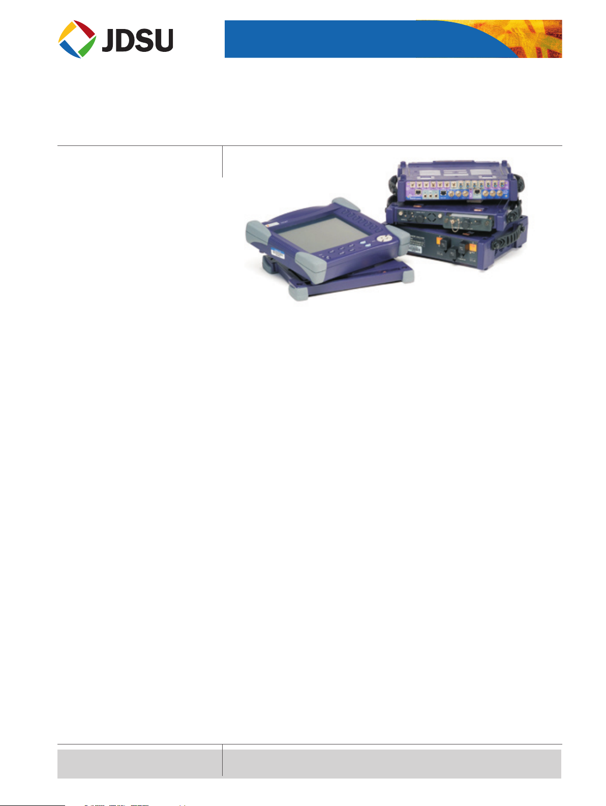
T-BERD 8000 Tester
All your optical network testing needs covered in a single platform
The power of one, performing the work of many
A powerful unit
• Flexible scalable platform
• Industry-leading size and weight
• Interchangeable modules
• Generates test results in seconds
• Fully automatic testing
• Combination of several tests
• Remotely controlled (via Ethernet, Fiber)
A single platform for
• Attenuation testing
• Dispersion testing
• DWDM systems testing
• New ber testing (attenuation prole)
• PDH/T-Carrier & SDH/SONET testing up to 10G
• Ethernet testing up to 10GigE
Variety of modules to meet all applications
• More than 20 OTDR modules
• Multifunction loss test module
• PMD modules
• CD module
• DWDM analyzers
• High-performance OSAs
• Transport module
Page 2
2
T-BERD 8000 Tester
Conventional fiber testing
• Ideal for eld measurements
• Large variety of OTDR modules
• Length measurement
• Fiber link attenuation
• Reection
• Splices/connector loss
• Insertion loss
• Optical return loss
• Fast and ecient testing
Fiber characterization testing
• Complete solution
• OTDR
• Chromatic dispersion (CD)
• Polarization mode dispersion (PMD)
• Attenuation prole
Environmental specifications
Temperature range
Operating on mains
(no options) −20 °C to +50 °C (−4 °F to 122 °F)
Operating, all options 0 °C to +40 °C
(32 °F to 104 °F)
Storage −20 °C to +60 °C (−4 °F to 140 °F)
Humidity 95% without condensing
EMI/ESD CE compliant
Main Specifications
T-BERD 8000 BASE
(typical at 25 °C)
Display
TFT color, 10’4 inches, LCD 800 × 600
TFT color, 10’4 inches,
LCD 800 × 600, High visibility
Touchscreen TFT color, 10’4 inches,
LCD 800 × 600, High visibility
Storage
Internal memory 16 MB
Hard disk (optional) min 20 GB
Floppy disk drive (optional) 3.5 inches,
MSDOS compatible
CD read/write (optional)
Input/output interfaces
RS232C, 2 × USB, VGA, RJ45 Ethernet,
RJ11 modem (optional)
Power supply, battery
Battery type standard removable
Li-Ion batteries
Operation time up to 16 OTDR hours
with two batteries and standard display,
Telcordia GR-196-CORE
Internal charger yes
Charging time <3 hours per battery
Trickle charge yes
DC input 19 to 25 V
Power supply,
AC/DC adapter Input 100 to 240 V,
50 to 60 Hz, 1.8 A, output 19 V DC/3.1 A
Size (w × h × d)
Mainframe only 320 × 265 × 55 mm/
(with back plate) 12.6 × 10.4 × 2.1 inches
Mainframe +
receptacle + 320 × 265 × 116 mm/
Battery pack 12.6 × 10.4 × 4.5 inches
Weight
Mainframe only 2.9 kg/6.39 lbs
(with back plate)
Mainframe + 5.4 kg/11.9 lbs
receptacle + Battery pack
(with one battery)
Comprehensive optical network platform
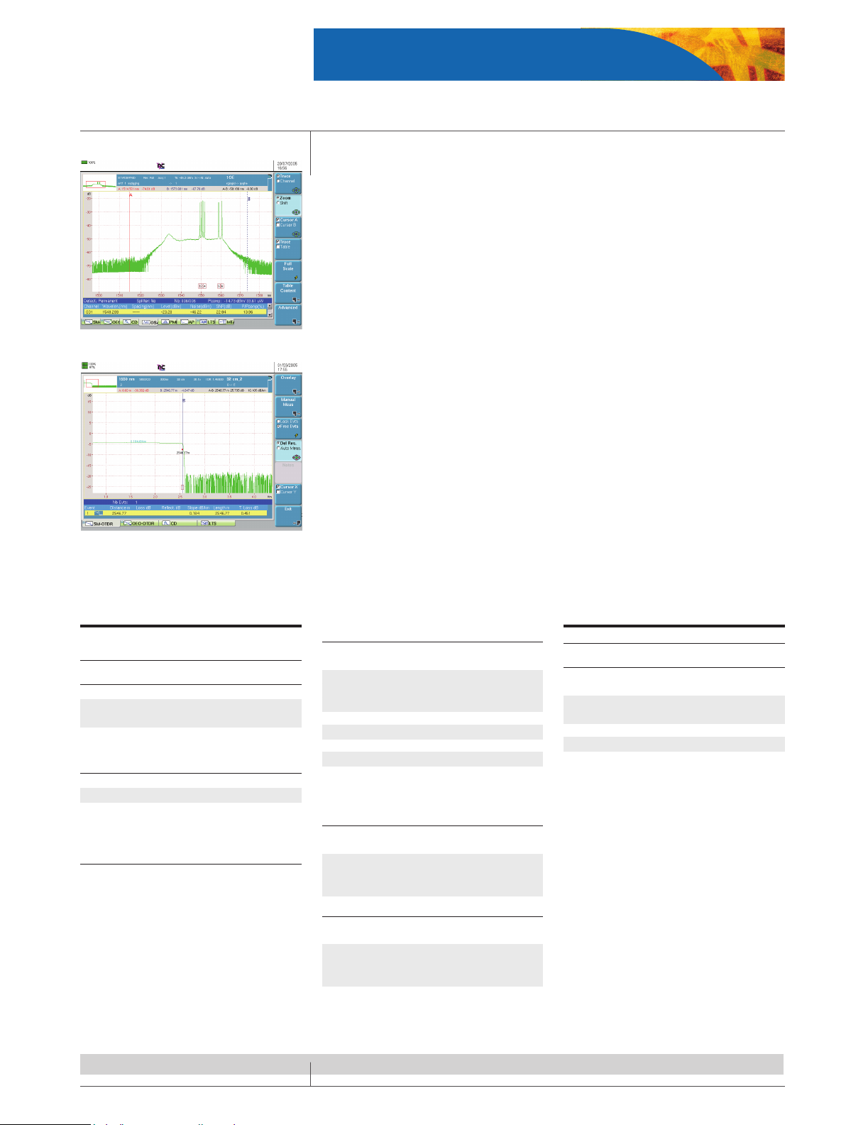
Amplified DWDM system analysis
FTTx OTDR testing
CWDM/DWDM testing
• Advanced testing
• Greater functionality
• Higher performance
• 1250 to 1650 nm DWDM measurements
• EDFA & DFB testing
• Channel isolation for BER analysis
• One button testing
• One single port analyzer with channel isola-
tor
• Dual port analyzer with channel isolation
• Transport module
FTTx testing
• During plant installation and maintenance
• Insertion loss
• Event loss
• Event reectance
• Distance to events
• Power level
• Total ORL or by section
Page 3
3
T-BERD 8000 Tester
High performance OTDR modules
Main specifications
High performance
multimode MM
Short range
singlemode SR
Medium range
singlemode DR
Long range
singlemode HD
Very long range
singlemode VLR
Ultra long haul
singlemode UHD
Central wavelength
(1)
850/1300 nm
± 20 nm
1310/1550 nm
± 20 nm
1310/1550 nm
± 20 nm
1310/1550/1625 nm ±
20 nm
± 10 nm for 1625 nm
1310/1550/1625 nm ±
20 nm
1310/1550/1625 nm ±
20 nm
± 10 nm for 1625 nm
Laser safety class (21
CFR)
Class 1 Class 1 Class 1 Class 1 Class 1 Class 1
Pulse width 3 ns to 200 ns 10 ns to 10 µs 5 ns to 10 µs 10 ns to 20 µs 3 ns to 20 µs 10 ns to 20 µs
Distance range Up to 80 km Up to 260 km Up to 260 km Up to 380 km Up to 380 km Up to 380 km
RMS dynamic range
(2)
25 dB/23 dB 35 dB/33 dB 37 dB/35 dB 42 dB/40 dB/40 dB 45 dB/43 dB/43 dB 46 dB/50 dB/46 dB
Event dead zone
(3)
1.5 m 3 m 1 m 4 m 0.8 m 4 m
Attenuation dead
zone
(4)
5 m 25 m 8 m 15 m 4 m 15 m
(1)
Central wavelength: Laser at 25 °C and measured at 10 µs for singlemode and 50 ns for multimode
(2)
RMS dynamic range: e one way dierence between the extrapolated back scattering level at the start of the ber and the RMS noise level, aer 3 minutes averaging.
(3)
Event dead zone: Measured at ± 1.5 dB down from the peak of an unsaturated reective event.
(4)
Attenuation dead zone: Measured at ± 0.5 dB from the linear regression using a FC/PC type reectance.
Wide range of modules
• Short haul to ultra long haul
• First to market 50 dB dynamic module (at 1550 nm)
• 1, 2, 3, 4 wavelengths per module (1310/1383/1490/1550/1625 nm)
• Multimode, singlemode modules
• Very short dead zones (up to 0.8 m event dead zone)
• Modules compatible with the T-BERD 6000 platform
Physical Fiber Testing
• OTDR measurements
• Optical return loss (ORL) measurement
• Insertion loss (IL) measurement
• Visual fault locator
• Alarm management with PASS/FAIL analysis
Large number of options
• Connection check with visual fault locator and videoscope
• Built in talk set with data transfer over ber capability
• PC soware solution for report generation
• Includes cable manager function
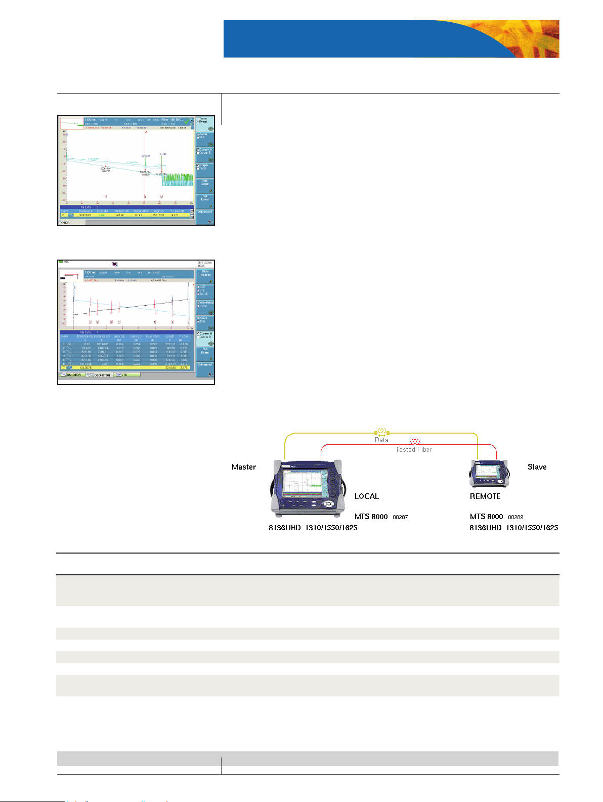
Automatic bi-directional measurement function
• Automate the acquisition process
• Check ber continuity
• File transfer through the ber
• True splice loss with both end analysis
Pass/Fail analysis
Bi-directional OTDR analysis
Page 4
4
T-BERD 8000 Tester
Multi-function Loss Test module
All in one module
• Single slot plug-in module for loss, back reection, and ber length measurements
• Testing at telecom wavelengths: 1310, 1550, and 1625 nm
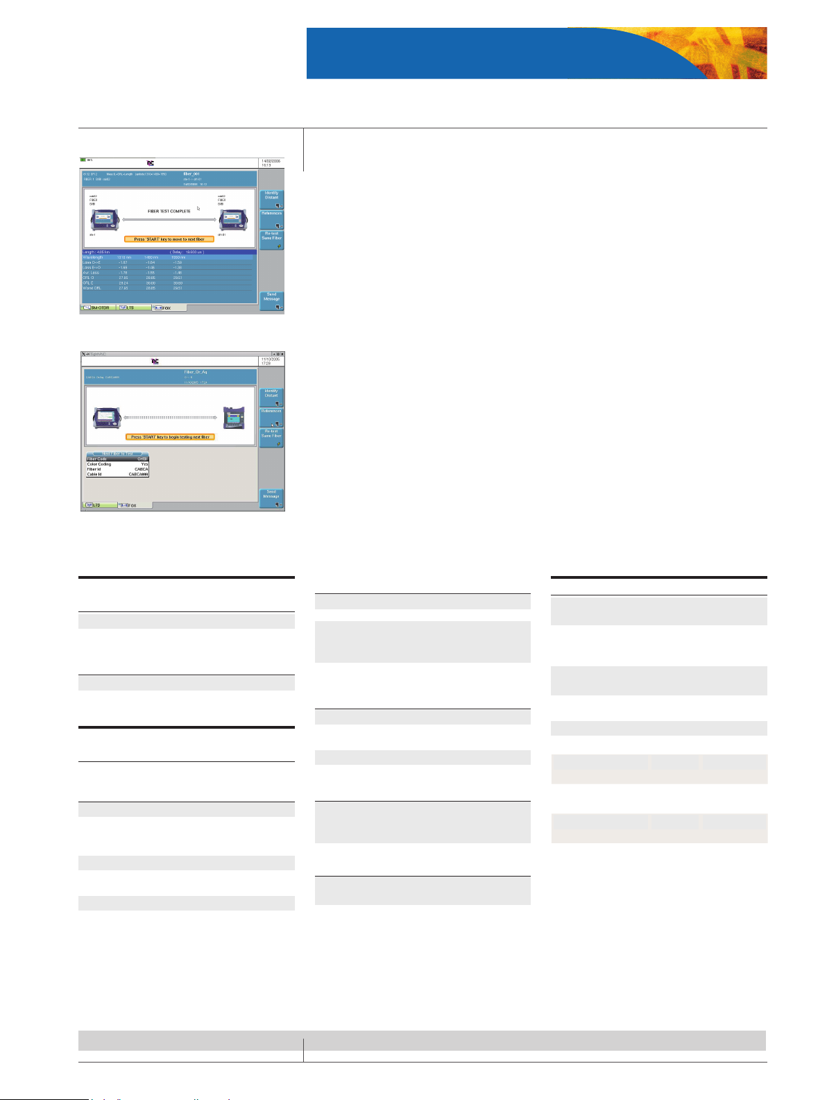
• One button automated testing
1- Continuity check
2- Automated bi-directional insertion loss (IL)
3- Automated bi-directional optical return loss (ORL)
4- Length testing
5- Pass/Fail analysis
6- Complete test results storage in both test units
• Additional standalone power meter
• Laser source to measure manually IL (TwinTest compatible)
• Manual ORL measurement possible with only one instrument
Best in class for FTTx Testing
• ITU-T G.983.3 compliant
• ree-wavelength version: 1310, 1490, 1550 nm
• Supports FTTx/PON testing
Multi-platform compatible module
• High performance for all types of networks: transport, metro, access, and FTTx/PON.
• Module compatible with the T-BERD 6000 Platform
• Can make measurement and communicate with another OFI module or a standalone
OFI-2000 Multi-function Loss Test Set.
Specifications
Multi-function Loss Test Module
(typical at 25° C)
Weight 0.6 kg (1.1 lbs)
Dimensions (w × h × d) 213 × 124 × 32 mm
(8.38 × 4.88 × 1.26 in)
Optical interfaces
Applicable fiber SMF 9/125 μm
Interchangeable
optical connectors FC, SC, DIN, etc…
Bi-directional test set specifications
(typical at 25° C)
Source function
(also valid for source mode)
Laser type Class 1 laser
Wavelength at 25° C 1310 ± 30 nm,
1490 ± 10 nm, 1550 ± 30 nm,
1625 ± 10 nm
Spectral bandwidth 5 nm maximum
Output level into
9/125 μm fiber (CW mode) -3.5 dBm
Modulated output average level 3 dB less
Level stability
Short term 15 min (T = ± 0.3 K) ± 0.02 dB
Long term 8 hours (T = ± 0.3 K) ± 0.2 dB
Modulation frequencies Continuous wave,
270 Hz, 330 Hz,
1 kHz, 2 kHz
TWINtest and auto-λ All wavelengths
activated one after the other
Loss test set function
Dynamic range 60 dB
Accuracy Loop back ± 0.25 dB /side-by-side
± 0.15 dB
Result resolution 0.01 dB
Optical return Loss
(also valid for manual ORL)
ORL measurement display range Up to 65 dB
(Limited to front end connector,
APC recommended)
Accuracy ± 0.5dB
Length function
Distance accuracy L<3 km: ± 50 m,
3 km<L<200 km : ±1.5%
Standalone power meter
Wavelength range
(adjustable per 1 nm) 800-1650 nm
Selectable wavelength 850/1300/1310/
1490/1510/1550/1625 nm
and one user-defined
Auto-λ detection (incl.TWINtest)
850/1310/
1490/1550/1625 nm
Modulation detection 270 Hz, 330 Hz,
1 kHz, 2 kHz
Display resolution 0.01 dB
Power level Standard High Power
Dynamic range +10 to
–60 dBm
+26 to
–55 dBm
Accuracy
(1310 nm, -20 dBm)
± 0.2 dB ± 0.25 dB
Detector type Ge filtered
InGaAs,2 mm
View results in one table with Pass/Fail indicator
Compatibility with the standalone OFI-2000
Page 5
5
T-BERD 8000 Tester
Approved and standardized method
• ITU-T G.650.1
• EIA/TIA FOTP-175-B
• IEC 60793-1-42
• Fast and reliable method
• Single end measurement
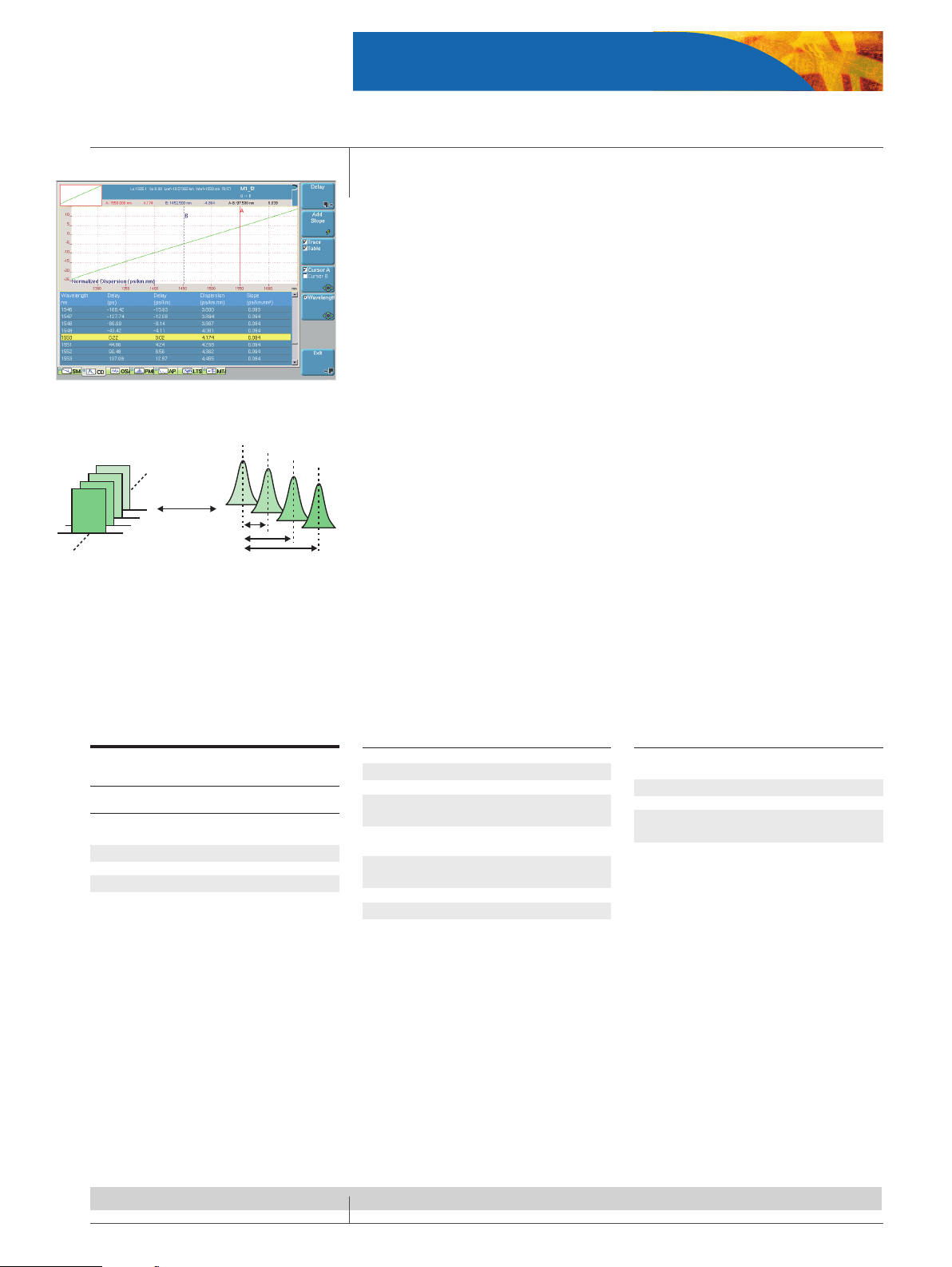
• Sectional analysis capability providing CD per ber section
• 3 functions in 1 : sources, CD, OTDR
• Suitable for all single-mode bers
• Cost eective method
• Not sensitive to shocks and vibrations (no moving parts)
• Module compatible with the T-BERD 6000 platform
High performance suitable for any metropolitan network
• Full ber test performed in only 45 seconds
• Large band coverage (1250 nm to 1650 nm)
• Wide measurement range
• Dynamic range (up to 120 km) dedicated for any metropolitan network conguration
Chromatic dispersion module for metropolitan networks
Specifications
Chromatic dispersion module
(typical at 25 °C)
OTDR mode
Central wavelength 1310/1480/
1550/1625 nm
Wavelength accuracy
(1)
± 5 nm
RMS dynamic range
(2)
39/38/37/37 dB
Event dead zone
(3)
6 m max.
Attenuation dead zone
(4)
30 m
Chromatic dispersion mode
Wavelength range 1255 to 1650 nm
Dynamic range Up to 120 km
Wavelength absolute accuracy ± 0.1 nm
Dispersion range 0.1 ps/nm*km
to 100 ps/nm*km
Zero dispersion wavelength
repeatability ± 0.5 nm*
Dispersion coefficient
repeatability** ± 0.2 ps/nm*km
Dispersion slope repeatability ± 1%
Measurement time From 40 s
Single menu for chromatic dispersion trace and table display
1
1
1
1
1
2
3
4
Pulse delay method complies with TIA/EIA FOTP-168
Optical source mode
Wavelength range typical 1310/1480/1550/
1625 nm ± 5 nm
Spectral width <10 pm
Power stability in 24 hours 1.5/3/3/3 dBm
Variable output power −10 dB
to calibrated power
(1) DFB lasers
(2) RMS dynamic range: e one way dierence between
the extrapolated back scattering level at the start of the ber
and the RMS noise level, aer 3 minutes averaging.
(3) Event dead zone: Measured at ± 1.5 dB down from the
peak of an unsaturated reective event.
(4) Attenuation dead zone: Measured at ± 0.5 dB from the
linear regression using a FC/PC type reectance.
* For 25 km G.655 link
** For a 75 km G.652 link, at 1550 nm.
Page 6
6
T-BERD 8000 Tester
A proven field-dedicated test method
• ITU-T G.650.2
• EIA/TIA FOTP 113
• IEC 60793-1-48
• Fast and reliable method
• Very accurate with the Fourier Transform
• Two ended test method (broadband source and receiver), no additional tools required
• Not sensitive to shocks and vibration (no moving parts)
• Best price/performance ratio on the market
• Module compatible with the T-BERD 6000 platform
High performance suitable for any fiber optic network
• High dynamic range with eld handheld source : 45 dB
• Wide measurement range with minimum measurable DGD value of 0.08 ps
• Fast measurement time from 6 seconds to improve eld eciency
• Measurement through multiple EDFA’s
• Field convenient instrument : light, small, long battery life...
• Statistics and long term monitoring
Maximum PMD values allowed for digital signal transmission:
Bit rate per
channel
SDH SONET Equivalent
timeslot
Max. PMD
delay
Max. PMD coefficient for a
100 km fiber length
1.2 Gb/s ––– OC-24 803 ps 80 ps 8 ps/√km
2.5 Gp/s STM-16 OC-48 401 ps 40 ps 4 ps/√km
10 Gb/s STM-64 OC-192 100 ps 10 ps 1 ps/√km
40 Gb/s STM-256 OC-768 25.12 ps 2.5 ps 0.25 ps/√km
Specifications
General specifications (typical at 25° C)
Weight 0.6 kg/1.3 lb
Dimensions (w × h × d) 213 × 124 × 32 mm
(8.38 × 4.88 × 1.26 in)
Optical interfaces
Applicable fiber SMF 9/125 µm
Interchangeable
optical connectors FC, SC, DIN, etc.
Polarization mode dispersion module
DUT
Polarized
Broadband
Source
Analyzer
OSA
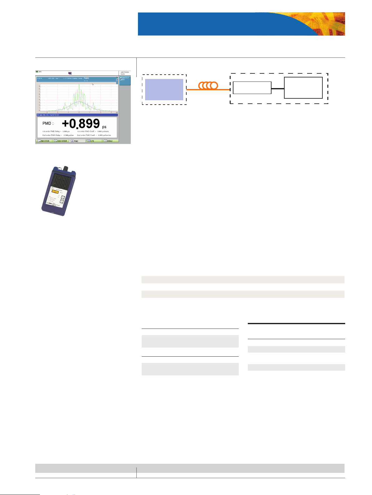
PMD test results with Pass/Fail analysis
OBS-15: Broadband polarized light source for PMD
measurement
Polarization mode dispersion module
(typical at 25 °C)
Dynamic range 45 dB
DGD measurement range
(1)
0.08 to 60 ps
DGD absolute
uncertainty
(2), (3)
± 0.02 ps ± 2% PMD
DGD repeatability
(2), (3)
± 0.025 ps
Measurement time
(4)
6 seconds,
independent of the PMD value
(1) Up to 150 ps in weak mode coupling
(2) Weak mode coupling, between the DGD range of 0.1
ps and 60 ps
(3) NPL standard traceable
(4) Without averaging
Page 7
7
T-BERD 8000 Tester
High-performance DWDM analysis
• Rugged reliable eld solution
• High wavelength accuracy without external calibration
• Fastest testing time ; 1.5 seconds full band scanning
• Built-in constant wavelength reference for online calibration
• Channel isolation for BER analysis
• Easy to use one button operation with auto-mode
• Patented dual port version
• Alarm management with pass/fail information
• Statistics and long term monitoring
CWDM/DWDM testing modules
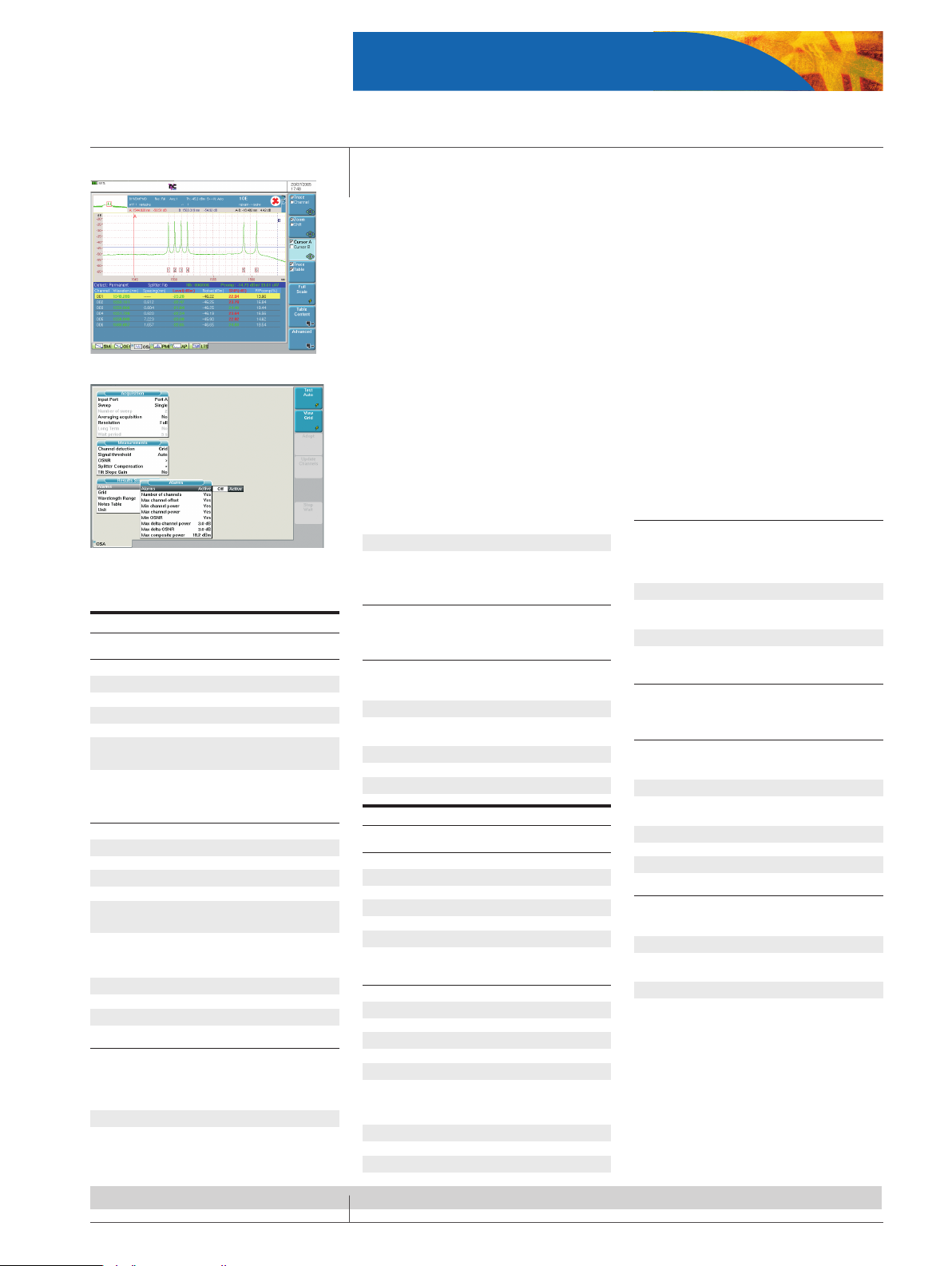
DWDM spectrum display with table of results
Test set-up display with Pass/Fail settings
Specifications
Full-band DWDM analyzers
Spectral measurement ranges
Wavelength range 1250 to 1650 nm
No. of optical channels 512
Wavelength calibration
(1)
internal, on-line
Wavelength accuracy
(2)
± 20 pm
Readout resolution 0.001 nm
Resolution bandwidth
(FWHM)
(3)
typ. 75 pm
Wavelength linearity
(over 10 nm) ± 10 pm
Power measurement ranges
Dynamic range
(4)
−75 to +23 dBm
Noise floor RMS (with averaging)
(3)
−75 dBm
Absolute accuracy
(3, 5)
±0.4 dB
Linearity
(6)
± 0.05 dB
Readout resolution 0.01 dB
Scanning time
(1250 to 1650 nm)
(7)
<1.5 s
Optical rejection ratio
(3)
at ±25 GHz (±0.2 nm) typ 35 dBc
at ±50 GHz (±0.4 nm) typ 45 dBc
PDL
(3)
± 0.1 dB
Flatness
(3)
± 0.2 dB
Level reproducibility
(8)
± 0.05 dB
Channel isolation option (OSA-161/201)
Using the channel isolation function, you can
drop channels for further signal analysis with
a BERT or a Q-factor meter.
Wavelength range 1250 to 1650 nm
Data rates up to 10.7 Gb/s
Spectral filter
bandwidth typ. 220 pm
Insertion loss typ. <10 dB
Tracking mode auto wavelength
control
Dual port option (OSA-201)
Simultaneous measurement of two fibers for
monitoring or component test applications.
Optical ports
(physical contact interfaces)
Input ports
OSA-160/161 1 × SM
OSA-201 2 × SM
Output port (drop port)
(OSA-161/201) 1 × SM
Interface Universal
Optical return loss >35 dB
Total safe power +23 dBm
High-performance DWDM analyzers
Spectral measurement ranges
Wavelength range 1250 to 1650 nm
No. of optical channels 512
Wavelength calibration
(1)
internal, online.
Wavelength accuracy
(2)
typ. ± 10 pm
Readout resolution 0.001 nm
Resolution bandwidth (FWHM)
(3)
typ. 60 pm
Wavelength linearity (over 10 nm) ± 10 pm
Power measurement ranges
Dynamic range
(4)
−75 to +23 dBm
noise floor RMS (with averaging)
(3)
−75 dBm
Absolute accuracy
(3, 5)
± 0.4 dB
Linearity
(6)
± 0.05 dB
Readout resolution 0.01 dB
Scanning time (1250 to 1650 nm)
(7)
<1.5 s
Optical rejection ratio
(3)
at ±25 GHz (±0.2 nm) typ. 45 dBc
at ±50 GHz (±0.4 nm) typ. 48 dBc
PDL
(3)
± 0.1 dB
Flatness
(3)
± 0.2 dB
Level reproducibility
(8)
± 0.05 dB
Channel drop option (OSA-301/303)
Using the channel isolation function, you can
drop channels for further signal analysis with
a BERT or a Q-factor meter.
Wavelength range 1250 to 1650 nm
Data rates up to 10.7 Gb/s
Spectral filter
bandwidth typ. 175 pm
Insertion loss typ. <10 dB
Tracking mode auto wavelength control
Dual-port option (OSA-303)
Simultaneous measurement of two fibers for
monitoring or component test applications.
Optical ports
(physical contact interfaces)
Input ports
OSA-300/301 1 × SM
OSA-303 2 × SM
Output port (drop port)
(OSA-301/303) 1 × SM
Interface universal
Optical return loss >35 dB
Total safe power +23 dBm
General specifications
Temperature
Operating +5 to +50 °C/41 to 122 °F
Storage −20 to +60 °C/−4 to 140 °F
Dimensions (w × h × d) 350 × 280 × 150 mm
13.8 × 11.0 × 5.9 in
Weight (module only) 2.5 kg/5.6 lbs
(1) Built-in, physical constant wavelength calibrator, needs
no re-calibration
(2) At 1520 to 1565 nm at 23 °C
(3) 1520 to 1565 nm at 18 to 28 °C
(4) Max. power per channel +15 dBm, total power
+23 dBm
(5) At −10 dBm
(6) −45 dBm to +10 dBm, at 23 °C
(7) Full span 400 nm, 4000 measurement samples, incl.
WDM table analysis
(8) 1 min, stable signal, const. temperature
Page 8
8
T-BERD 8000 Tester
Combined WDM, PMD, AP testing module
A unique solution combining WDM, PMD, and AP (Attenuation Profile) test functions in one plug-in
module
• Full-band most compact solution for WDM testing (from 1260 to 1640 nm)
• High-performance PMD module with dierential group delay (DGD) measurement in the
range of 0.08 ps to 60 ps and high dynamic range of 45 dB
• Attenuation prole provides total loss and dB/km values over a 1260 nm to 1640 nm wave-
length range, with a dynamic range of 45 dB
• Shock-proof and vibration-proof instrument with no moving parts (drop tested at 70 cm)
• High-performance module with maximum portability (0.6 kg)
• Module compatible with the T-BERD 6000 platform
Specifications
81WDMPMD module (typical at 25°C)
General specifications
Weight 0.6 kg (1.1 lb)
Dimensions (w × h × d) 213 × 124 × 32 mm
(8.38 × 4.88 × 1.26 in)
Optical interfaces
Applicable fiber SMF 9/125 μm
Interchangeable
optical connectors FC, SC, DIN, etc.
WDM technical specifications (typical at 25°C)
Wavelength range 1260 nm to 1640 nm
Sweep time (real time) 3 s
Accuracy
(1)
±10 pm
Display resolution 1 pm
Minimum spacing between channels 10 GHz
Optical bandwidth (FWHM)
(2)
30 pm
Power level
Display range -90 dBm at +30 dBm
Display resolution 0.01 dB
Measurement range on a channel -79 dBm
at +10 dBm
Noise floor
(3)
-86 dBm
Maximum admissible power
(before signal cut off )
- Total +20 dBm
- For one channel +10 dBm
Accuracy
(4)
±0.5 dB max
Linearity
(5)
±0.2 dB
Flatness
(6)
±0.2 dB
Polarization Dependence Loss (PDL) ±0.15 dB
Optical return loss (ORL) 35 dB
Optical rejection ratio (ORR)
(7)
40 dB at 100 GHz from the carrier
35 dB at 50 GHz from the carrier
(1) Between 1525 nm and 1620 nm from -40 dBm to
+5 dBm
(2) Between 1525 nm and 1570 nm
(3) With averaging at 1550 nm
(4) At -30 dBm and 1550 nm (excluding the uncertainty due
to the input connector)
(5) At 1590 nm from 0 to -40 dBm
(6) Between 1525 nm and 1620 nm (reference = 1550 nm)
(7) From the top of a carrier, between 1530 nm and 1605 nm
at 0 dBm
PMD technical specifications (typical at 25°C)
Dynamic range 45 dB
DGD measurement range
(1)
0.08 ps to 60 ps
DGD absolute uncertainty
(2), (3)
± 0.02 ps
± 2% PMD
DGD repeatability
(2), (3)
± 0.025 ps
Measurement time
(4)
6 seconds,
independent of the PMD value
(1) Up to 150 ps in weak mode coupling
(2) Weak mode coupling, between the DGD range of 0.1
ps and 60 ps
(3) NPL standard traceable
(4) Without averaging
AP technical specifications (typical at 25°C)
Dynamic range 45 dB
Measurement time
(1)
6 seconds
(1) Without averaging
Handheld broadband source (OBS-15)
Optical interfaces
Applicable fiber SMF 9/125 μm
Interchangeable
optical connectors FC, SC, DIN, etc.
Power supply
Battery operation NiMH, type AA
(rechargeable, exchangeable, 2 pieces)
Operating time approx. 2.5 h
AC operation by means of SNT-92 AC/DC
adapter/charger
Nominal range of use 100 to 240 V, 50/60 Hz
Operating temperature range 0 °C to +45 °C
Weight (including batteries) 0.55 kg (1.2 lb)
Dimensions (w × h × d) 95 × 49 × 185 mm
(0.37 × 0.19 × 0.73 in)
Broadband source module
Wavelength range
BBS1 1485 nm to 1640 nm
BBS2 1260 nm to 1640 nm
Optical interfaces
Applicable fiber SMF 9/125 μm
Interchangeable
optical connectors FC, SC, DIN, etc.
Weight 0.5 kg (1.1 lb)
Dimensions (w × h × d) 213 × 124 × 32 mm
(8.38 × 4.88 × 1.26 in)
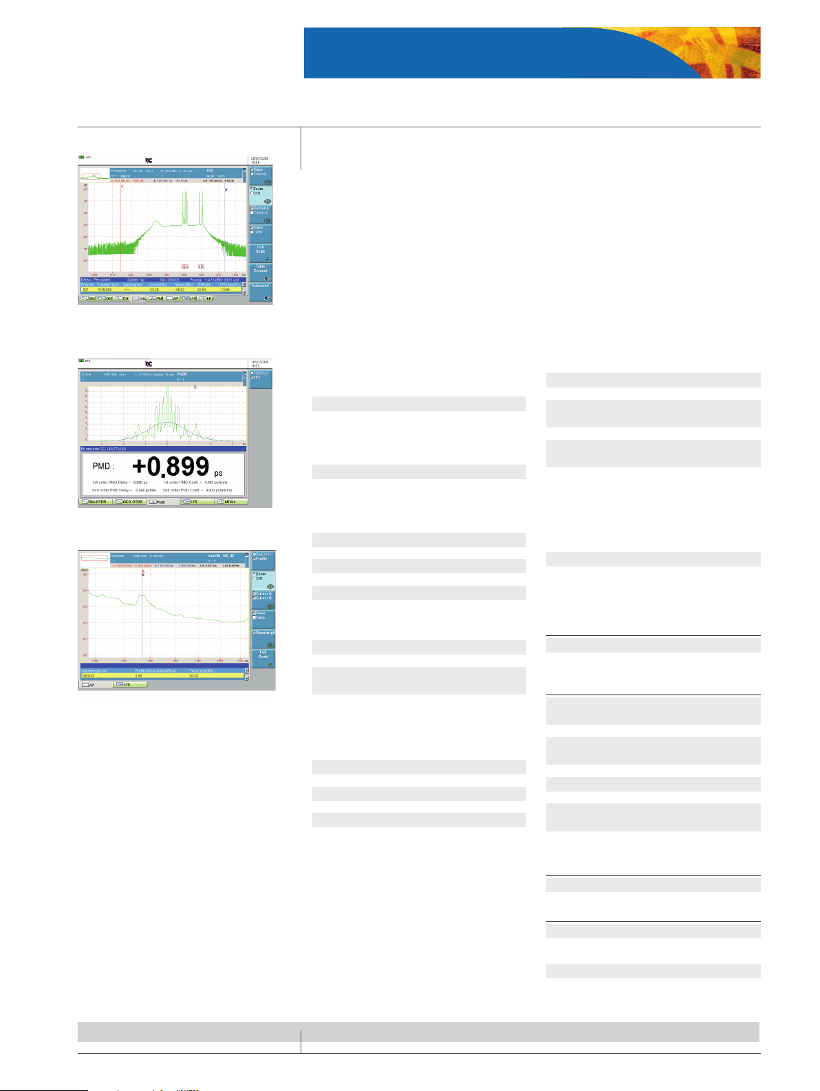
Amplified DWDM system analysis using the
E81WDMPMD module
PMD test results showing the first order and second
order PMD values
An attenuation profile showing a loss vs. wavelength measurement
Page 9
9
T-BERD 8000 Tester
Transport module
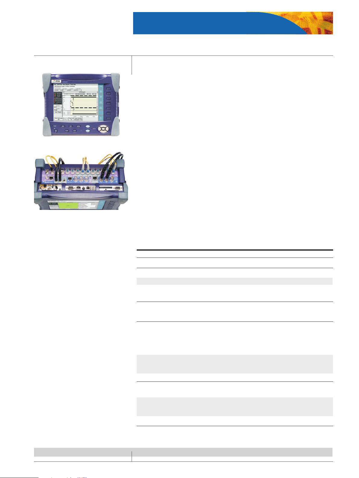
• Contained in one 5 cm module
– PDH / T-carrier Interfaces include DS1, E1, E3, DS3, E4, STS-1 and STM-1e
– SDH/SONET Interfaces include 155M/622M/2.5G/10G (1310 nm, 1550 nm)
– Ethernet Interfaces include 10/100/1000 Mb/s electrical and 1 GigE Optical (850 nm,
1310 nm and 1550 nm)
– 10GigE LAN + WAN (850 nm, 1310 nm and 1550 nm)
• Only 2.5 kg fully populated
• Fully scalable to meet your current and future needs
• Optical and electrical signal level measurements
• Up to 2.5 hours at 10 Gb/s rates with one Battery (2 batteries possible)
• SDH/SONET testing
Muxed payload generation and analysis
Concatenated Signals
Automatic Protection Switching (APS)
Overhead Byte Manipulation and Analysis
Round Trip delay (RTD)
• Ethernet testing
Single and Dual Port Ethernet conguration
Testing on Layer 1, 2 and 3 (IP)
Automated RFC2544 testing
Loop-up /loop-down of far-end device
SDH/SONET, Ethernet and 10Gig Ethernet transport testing module
Specifications
Transport module
Optical interfaces
Optical connector types FC, SC, ST or LC
Wavelength 850, 1310 or 1550 nm
Fiber mode compatibility 1310 and 1550 nm, – singlemode fiber, 850 nm – multimode fiber
Electrical interfaces
Electrical connector types Bantam, BNC, RJ-45
Ethernet testing
Layer 2 (Ethernet) Traffic
Generation
Constant, Bursty, Ramp, Flood
Configurable Source and Destination Address, Frame Format,
Type Field (for DIX), Frame Length
(including Jumbo and Undersized), VLAN Tag, Pause Frames, payload, Utilization %
Layer 3 (IP) Traffic
Generation
Configurable Source and Destination IP Address, DNS Type, DNS
Server, Tx Payload, TOS/DSCP, TTL, Packet Size Length (34 – 1500
bytes), Ping, Trace route
SDH/SONET
Anomaly/Errors generation
and analysis
B1, B2, B3, HP-REI, MS-REI, LP-BIP, LP-REI
Defects/Alarms generation
and analysis
LOS, LOF, RS-TIM, MS-AIS, MS-RDI, AU-LOP, AU-AIS, HP-UNEQ, HPRDI, HP-TIM, HP-PLM, TU-LOP, TU-AIS, TU-LOM, LP-UNEQ, LP-RDI,
LP-TIM, LP-PLM, LP-RFI
Performance standards
G.821, G.826, G.828, G.829, T1.231, T1.510, M.2100, M.2101
Page 10
10
T-BERD 8000 Tester
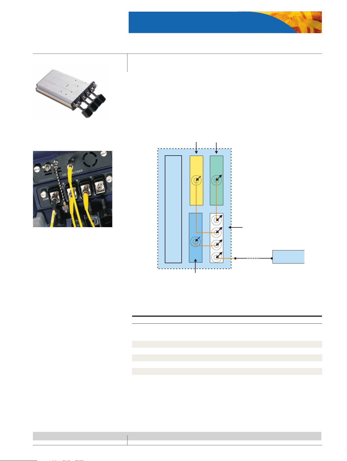
Multiple test access module
Innovative module with up to six interconnected test
functions
Fiber under test
Broadband source
CD/OTDR
PMD
Attenuation Profile
T-BERD 8000
OLTS (IL/ORL)
Multi-test access unit allowing a single
connection/disconnection of the fiber
under test for multiple measurements
MTAU interconnections
Multi Test Access Unit Module
• Fiber Characterization made easier, ber commissioning (OTDR & IL)
• 25% time saving for ber characterization
• Up to 6 interconnected test functions (OTDR, CD, PMD, IL, SA, ORL)
• Reduces ber connect/disconnect
• Up to 3 modules connected
• Automatically switches from one module to another
How the MTAU functions
Specifications
Multi-test access unit
E81MTAU2 (2 ports) E81MTAU3 (3 ports)
Wavelength range 1260 to 1640 nm 1260 to 1640 nm
Insertion loss (max) 1 dB 1.5 dB
Return loss (max) 50 dB 50 dB
PDL
(1)
(max) 0.1 dB 0.1 dB
Repeatability
(2)
(max) 0.01 dB 0.01 dB
(1) Polarization dependent loss
(2) At constant temperature and polarization
Page 11
11
T-BERD 8000 Tester
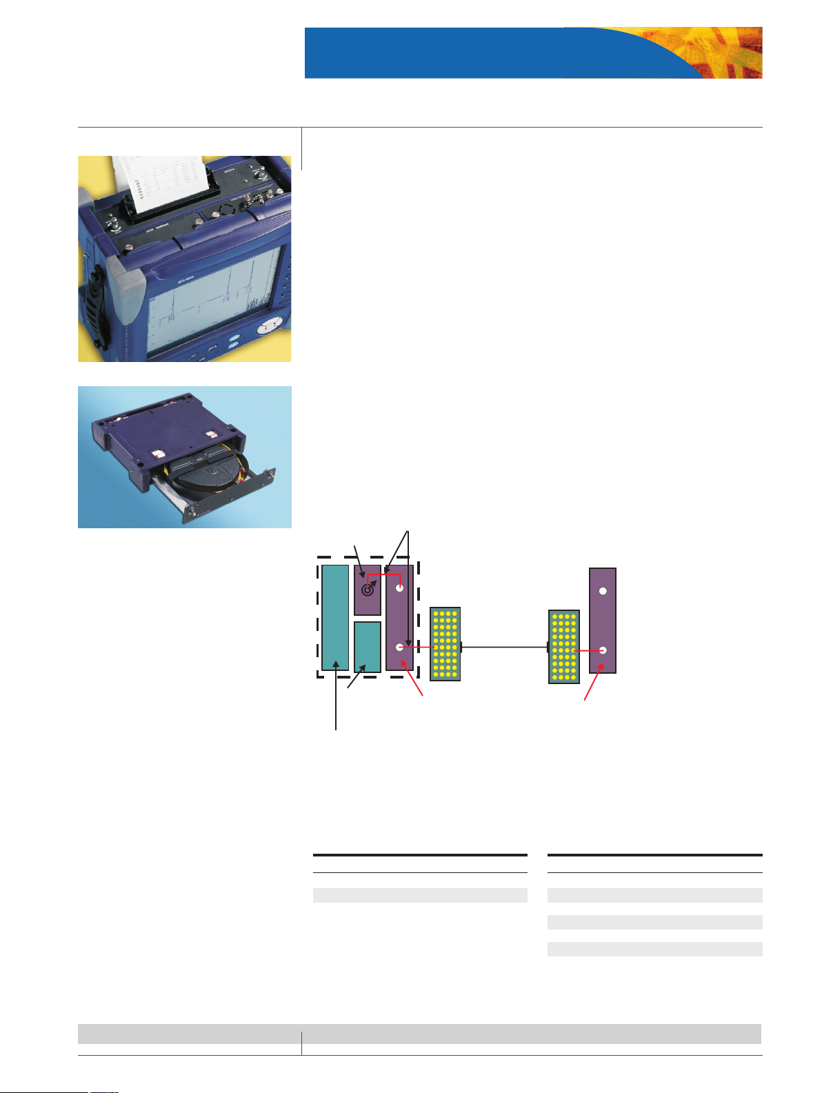
Internal Thermal Printer
• On-site documentation
• Shock proof
• High quality printing
• Optimized for trace and table of events printing
• Improves user productivity by instant delivery of trace record
Launch Fiber Module for OTDR Applications - allows full characterization of first and last connectors
• Improves testing at 1310 nm/1550 nm and 1625 nm
• Single mode bers
• 2 or 4 km long
• Includes 2 patchcords (3 m)
• Rugged design for eld application
• Can be used either inserted in the T-BERD 8000 platform (permanent availability) or as a
standalone launch ber
• Can be used in 2 positions; opened or closed
• Compatible with launch ber management within OTDR rmware
Utility modules
Fiber under test
Patch panel Patch panel
Module slot available
Extractable jumpers from
the launch fiber module
OTDR module
User interface
module
Launch fiber module
plugged into the test
platform
Launch fiber module
used as standalone
Launch fiber module
Internal printer with launch cable
Specifications
Thermal printer module
Printer type Thermal printer
Quality 832 dots/line
Paper width 112 mm paper width
How the launch fiber module functions
Launch fiber module
Fiber type Standard singlemode fiber (G.652)
Fiber length 2 km or 4 km ± 5%
Linear attenuation at 1550 nm 0.20 dB/km
Insertion loss <0.5 dB
Return loss >35 dB
Weight 2.3 kg/5.1 lbs
Size (l × w × d) 310 × 255 × 60 mm
12.2 × 10 × 2.4 in
Page 12
12
T-BERD 8000 Tester
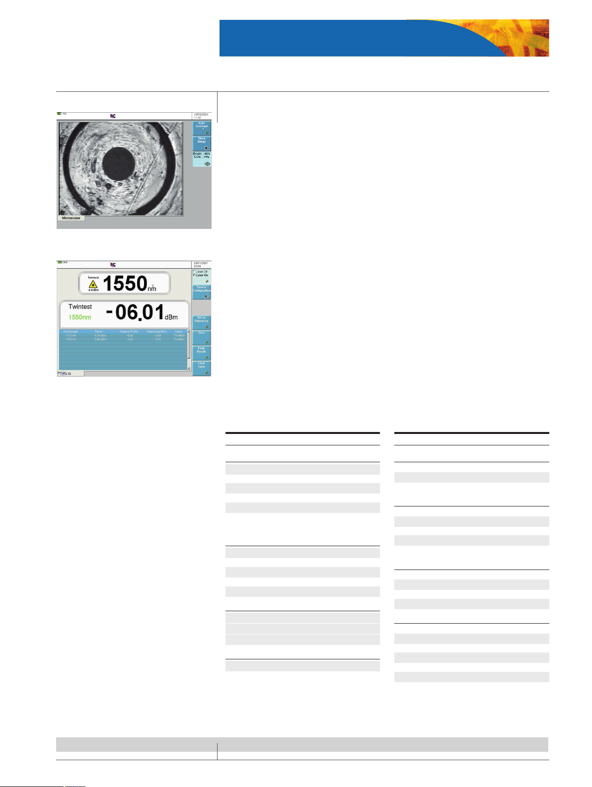
Connector Inspection Scope
• Video inspection probe for ber optic terminations
• For inspection of patchcords and patch panels
• 250 or 400 magnication
• Uses T-BERD 8000 large screen (10.4”)
• Possibility to freeze the image
• Image storage and reload
• Comparison with 3 other images on the same screen
• Compatible with standard connectors including SC, ST, FC and LC
Built-in Optical Talkset
• Suitable for any application
• Cost-eective solution
• Suitable for use in central oces (unlike cell phones)
• Data transfer capability: le exchange or remote control
• Used also for full automatic bi-directional measurements
Insertion Loss Measurements
• Power meter integrated in T-BERD 8000 mainframe
• Multi-wavelength laser source with CW or modulated signals
• Easy loss measurements of a jumper or patchcord
635 nm Visual Fault Locator
• Universal push/pull for all 2.5 mm connector types
Fiber Scope, Loss Test Set, Talkset and VFL functions
Specifications
Optical video inspection probes
Physical characteristics
Operating temperature 0 °C to 50 °C
Storage temperature -20 °C to 50 °C
Humidity 95% non condensing
Interface USB
Weight 115.6 g (4.08 oz.)
Dimensions (w × h × l) 45.7 × 43.2 × 140 mm
(1.8 × 1.7 × 5.5 in)
Optical characteristics
Magnification 200× or 400×
Light source blue LED, internal to probe
Lighting technique coaxial
Focus control adjustable, in probe
Max. input power +30 dBm
Adapter tips
Termination-specific probe tips available:
FC, SC, ST, LC and other types for 1.25 mm &
2.5 mm ferrules.
Storage
File format JPEG, BMP
Optical interfaces (optional)
Power meter
Power level +10 to −55 dBm,
Calibrated wavelengths 850, 1310, 1550 nm
Connector type universal push/pull
Talk set
Wavelength 1550 nm ± 30 nm
Dynamic range >45 dB
Function With data/file transfer,
Laser safety Class 1 laser,
Connector type Field interchangeable
VFL
Wavelength 635 nm ± 15 nm
Output power level <1 mW
Laser safety Class 2 laser,
Connector type Universal push/pull
CW light source
Wavelengths (selection) 1310/1550/1625 nm
Output power level -3.5 dBm
Spectral width <5 nm
Stability in 15 min ± 0.02 dB
Stability in 8 hours ± 0.2 dB
Laser Safety Class 1 laser
Connector type Field interchangeable
Connector surface inspection
Loss test set results display
Page 13
13
T-BERD 8000 Tester
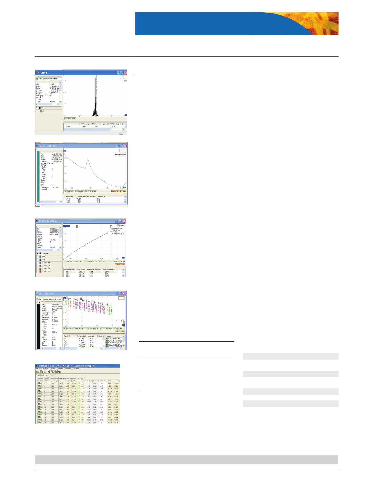
OFS-100 Fiber Trace Results Analysis
• OTDR, CD, PMD, AP, IL/ORL and OSA results analysis
• Batch processing capability via an automation process
• Pass/Fail function
• Customized printouts
• Ideal for report generation on single ber
OFS-200 FiberCable Acceptance Report Generation
• Direct access keys for easy process and eciency
• Complete ber characterization reporting capability including bi-directional OTDR, CD,
PMD, AP, IL and ORL results
• Advanced OTDR functions for loop back and mid-point management
• Powerful report preview to avoid errors during processing
• Ideal for report generation on multiple bers
Specifications
OFS-100 FiberTrace
OFS-200 FiberCable
Compatibility with all files generated by the
MTS-5000, T-BERD 8000 and T-BERD 6000 platforms, OFI-2000 and ONT platform OSA data.
FiberCable includes all FiberTrace functions.
PC requirements
An IBM Pentium 133 MHz PC or 100% compatible computer (Pentium II 233 MHz or above
recommended)
A hard drive and a CD-ROM drive
16 MB or more of memory (64 MB recommended)
A mouse pointing device
Microsoft Windows™ version 95, 98, 2000, NT,
or XP
Microsoft Excel™
Memory requirements for Microsoft Excel™
Report macro: 48 MB or more of memory
(128 MB recommended)
A 800 × 600 pixels monitor (1152 × 864 or
above recommended)
PC softwares: Post-process and document your field measurements
Example of OTDR results page
Example of cable report
Example of PMD results page
Example of AP results page
Example of CD results page
Page 14

14
Ordering information
T-BERD 8000 Tester
T-BERD 8000
Base instrument options
ETB8000bt T-BERD 8000 platform with battery pack
E8100 Receptacle for two plug-in modules
E80HVCol High visibility TFT color display
E80HVTCol High visibility touchscreen TFT color display
E80Hdisk Hard disk drive
E80FD Extractable floppy disk drive
E80CDRW Extractable R/W CD-ROM drive
E80MDM Built-in PSTN modem
E80VFL VFL with UPP connector
E80TS Optical talk set
E80PM Optical power meter with UPP connector
(2.5 mm provided as standard)
E8036LTSTS Optical loss test set with talk set 1310/1550/1625 nm
Main accessories
E80keyB External keyboard
E80LiIon Additional Li-Lon rechargeable battery
E80Scase1 Wrap around soft carrying case for T-BERD 8000 and
2 plug-ins receptacle configuration
E80Scase2 Soft carrying case for long configuration
E80Scase3 Soft carrying case for T-BERD 8000 and 2-slot recep-
tacle, or transport or OSA-160/200 module
E80Hcase Hard transit case for long configuration
C80Hcase5 Hard carrying case for T-BERD 8000 and 2-slot recep-
tacle, or transport or OSA-160/200 module
Application software
EOFS100 Optical FiberTrace software (for post-analysis)
EOFS200 Optical FiberCable software (for cable acceptance
report generation)
T-BERD 8000 modules
Multimode OTDR plug-in module
E8123MM High resolution 850/1300 nm
Singlemode OTDR plug-in modules
E8126SR Short range 1310/1550 nm
E8126DR Medium range high res. 1310/1550 nm
E8126HD Long range 1310/1550 nm
E8127HD Long range 1625 nm
E8136HD Long range 1310/1550/1625 nm
E8126VHD Very long range 1310/1550 nm
E8127VHD Very long range 1625 nm
E8129VHD Very long range 1550/1625 nm
E8126UHD Ultra long range 1310/1550 nm
E8136UHD Ultra long range 1310/1550/1625 nm
Chromatic dispersion plug-in module
E5083CD Medium range 1310/1480/1550/1625 nm OTDR/CD
module
E508XLS 1310/1480/1550/1625 nm DFB source option
Polarization mode dispersion plug-in modules
E81PMD PMD module (1480 to 1640 nm)
E81WDMPMD PMD module (1260 to 1640 nm) combined with WDM
and AP
EOBS15 Stand-alone broadband source
E81BBS1 1480-1640 nm broadband source module
E81BBS2 1260-1640 nm broadband source module
OFI plug-in module
E8126OFI1 1310/1550 nm OFI plug-in module - standard power
E8126OFI2 1310/1550 nm OFI plug-in module - high power
E8136OFI1 1310/1550/1625 nm OFI plug-in module - standard
power
E8136OFI2 1310/1550/1625 nm OFI plug-in module - high power
E8132OFI1 1310/1490/1550 nm OFI plug-in module - standard
power
E8132OFI2 1310/1490/1550 nm OFI plug-in module - high power
High-performance OSA modules
2281/91.01 OSA-160 Single port analyzer
2281/91.12 OSA-161 Single port analyzer with channel isolator
option
2281/91.14 OSA-201 Dual port analyzer with channel isolator
option
2281/91.31 OSA-300 High-performance analyzer
2281/91.32 OSA-301 High-performance analyzer with channel
isolator option
2281/91.34 OSA-303 High-performance dual port analyzer with
channel isolator option
E81WDM 1485-1640 nm WDM plug-in module
Transport module configurations
C83XX SDH/SONET configuration
C84XX Ethernet configurations
C85XX SDH/SONET & Ethernet configurations
Utility modules
Multi-test access unit plug-in module
E81MTAU2 Up to 2 test ports
E81MTAU3 Up to 3 test ports
Launch fiber module
E82LFSM2 2 km singlemode G.652
E82LFSM4 4 km singlemode G.652
Page 15

15
Ordering information
T-BERD 8000 Tester
Thermal printer module
E82Printer Thermal printer module
Accessories
Optical video inspection probes
EFSCOPE250 Optical inspection probe, 250× through USB
EFSCOPE400 Optical inspection probe, 400× through USB
Connectors and adapters
Optical inspection
ETIPSCAPC SC/APC tip, bulkhead adapter
ETIPE2000 E2000 tip, bulkhead adapter
ETIPSCPC SC/PC tip, bulkhead adapter
ETIPU125MM Patch cord tip for 1.25 mm ferrule
ETIPU25MM Patch cord tip for 2.5 mm ferrule
ETIPFCAPC FC/APC tip, bulkhead adapter
ETIPSTPC ST/PC tip, bulkhead adapter
ETIPLC LC tip or bulkhead adapter
ETIPFCPC FC/PC tip, bulkhead adapter
ETIPMPOAPC MPO/APC tip, bulkhead adapter
ETIPMPO MPO tip, bulkhead adapter
Optical connectors
Universal singlemode connectors
EUNIPCFC, EUNIPCSC, EUNIPCST, EUNIPCDIN, EUNIPCLC, EUNIAPCFC, EUNIAPCSC, EUNIAPCST,
EUNIAPCDIN, EUNIAPCLC
For more information on test adapters, cables, and fiber optic couplers, please refer to the separate
datasheet entitled “JDSU Fiber Optic Test Adapters and Cables”.
Page 16
All statements, technical information and recommendations related to the products herein are b ased upon information believed to be reliable or accurate. However, the accuracy or completeness thereof is not guar anteed,
and no responsibility is assumed for any inaccuracies. e user assumes all risks and liability whatsoever in connection with the use of a product or its applications. JDSU reserves the right to change at any time without notice
the design, specications, function, t or form of its products described herein, including withdrawal at any time
of a product oered for sale herein. JDSU makes no representations that the products herein are free from any
intellectual property claims of others. Please contact JDSU for more information. JDSU and the JDSU logo are
trademarks of JDS Uniphase Corporation. Other trademarks are the property of their respective holders.
© 2006 JDS Uniphase Corporation. All rights reserved.
30137429 001 0707 TB8000CONS.DS.FOP.TM.AE
Test & Measurement Regional Sales
NORTH AMERICA
TOLL FREE: 1 866 228 3762
FAX: +1 301 353 9216
LATIN AMERICA
TEL:+55 11 5503 3800
FAX:+55 11 5505 1598
ASIA PACIFIC
TEL:+852 2892 0990
FAX:+852 2892 0770
EMEA
TEL:+49 7121 86 2222
FAX:+49 7121 86 1222
WEBSITE: www.jdsu.com
T-BERD 8000 Tester
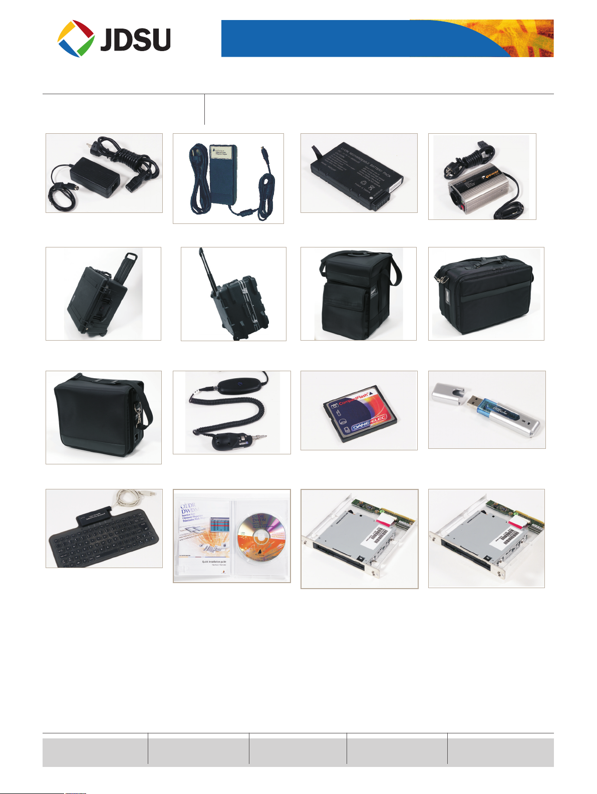
E80PWE, E80PWUK, E80PWUS: Standard AC
adapter/charger
E80HPWE, E80HPWUK, E80HPWUS: Adapter/charger for transport module
E80Lilon: Additional Li-Ion rechargeable
battery
E80lighter: Cigarette lighter power adapter
E80HCase: Hard Transit Case for long configuration (multiple modules)
E80HCase5: Hard carrying case – single
module configuration
E80SCase2: Soft carrying case for multiple
module platform
E80SCase3: Soft carrying case for single
module platform
E80SCase1: Wrap around case for 8000
platform and receptacle
EFSCOPE250, EFSCOPE400: Optical video
inspection probe
E80CFAPP: Transport module application
card
E80USBMEM: USB stick 128 MB
E80keyB: USB keyboard
EOFS100, EOFS200: FiberTrace and FiberCable softwares
E80FD: Extractable floppy disk drive
E80CDRW: Extractable R/W CD ROM drive
Useful accessories
 Loading...