

Page 1
Compact Multiprotocol I/O Module for Ethernet
8 Digital PNP Inputs
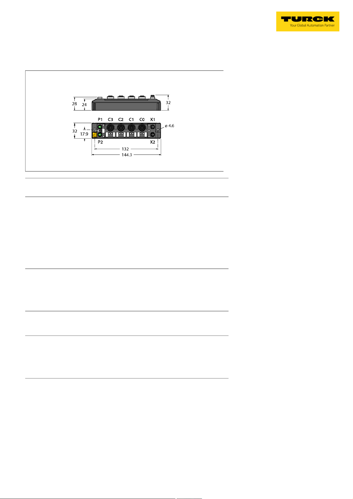
TBEN-S2-8DIP
Type designation TBEN-S2-8DIP
Ident-No. 6814073
Supply
Supply voltage 24 VDC
Admissible range 18…30 VDC
Total current max. 4 A per voltage group V1
Voltage supply connection 2 × M8, 4-pin
Operating current V1: max. 150 mA mA
Sensor/Actuator supply V
Electrical isolation galvanic isolation of the voltage groups V1 and V2,
AUX1
Supply ports C0-C3 from V1
supply Pin1 switchable per port short-circuit protect-
ed, 0.5A per port
voltages up to 500 VAC
■ Pin1 switchable per I/O port
■ Diagnosis of supply to each I/O port
■ FLC/ARGEE programmable
■ PROFINET® device, EtherNet/IP™ de-
vice or Modbus® TCP slave
■ Integrated Ethernet switch
■ Supports 10 Mbps/100 Mbps
■ 2x M8, 4-pin, Ethernet fieldbus connec-
tion
■ Glass-fiber reinforced housing
■ Shock and vibration tested
■ Fully potted module electronics
■ Protection classes IP65 / IP67 / IP69K
System data
Fieldbus transmission rate 10 Mbps/100 Mbps
Fieldbus connection technology 2 × M8, 4-pin
Protocol detection automatic
Web server default: 192.168.1.254
Service interface Ethernet via P1 or P2
Field Logic Controller (FLC)
Supported from firmware version 3.0.1.0
Released from ARGEE version 2.0.25.0
Modbus TCP
Addressing Static IP, DHCP
Supported function codes FC1, FC2, FC3, FC4, FC5, FC6, FC15, FC16, FC23
Number of TCP connections 8
Input register start address 0 (0x0000 hex)
Output register start address 2048 (0x0800 hex)
EtherNet/IP™
Addressing acc. to EtherNet/IP™ specification
Quick Connect (QC) < 500 ms
Device Level Ring (DLR) supported
Class 3 connections 3
Class 1 connections 10
Input Assembly Instance 103
Output Assembly Instance 104
Configuration Assembly Instance 106
Edition • 2019-01-21T19:23:56+01:00
1 / 6 TURCK Inc.
Page 2

Compact Multiprotocol I/O Module for Ethernet
8 Digital PNP Inputs
TBEN-S2-8DIP
PROFINET
Addressing DCP
Conformance class B (RT)
MinCycleTime 1 ms
Fast Start-Up (FSU) < 500 ms
Diagnostics acc. to PROFINET alarm handling
Topology detection supported
Automatic addressing supported
Media Redundancy Protocol (MRP) supported
Digital inputs
Number of channels 8
Connectivity inputs M12, 5-pin
Input type PNP
Type of input diagnostics Channel diagnostics
Switching threshold EN 61131-2 Typ 3, PNP
Low level signal voltage < 5 V
High level signal voltage > 11 V
Low level signal current < 1.5 mA
High level signal current > 2 mA
Input delay 0.2 ms / 3 ms ms
Electrical isolation galvanic isolation to P1/P2
, voltages up to 500 VDC
Standard/Directive conformity
Vibration test acceleration to 20 g
acc. to EN 60068-2-6
Shock test acc. to EN 60068-2-27
Drop and topple acc. to EN 60068-2-31/IEC 60068-2-32
Electromagnetic compatibility acc. to EN 61131-2
Approvals and certificates CE, FCC
UL Certificate cULus LISTED 21 W2, Encl.Type 1 IND.CONT.EQ.
General Information
Dimensions (W x L x H) 32 x 144 x 32mm
Operating temperature -40…+70 °C
Storage temperature -40…+85 °C
Altitude max. 5000 m
Protection class IP65
IP67
IP69K
MTTF 314 years acc. to SN 29500 (Ed. 99) 20 °C
Housing material PA6-GF30
Housing color Black
Material label Polycarbonate
Halogen-free yes
Mounting 2 mounting holes Ø 4.6 mm
Edition • 2019-01-21T19:23:56+01:00
2 / 6 TURCK Inc.
Page 3

Compact Multiprotocol I/O Module for Ethernet
8 Digital PNP Inputs
TBEN-S2-8DIP
Accessories
It is strongly recommended to use only pre-assembled Ethernet
cables!
Ethernet cable (example):
M8-M8:
PSGS4M-PSGS4M-4413-1M
Ident. no. U-55718
M8-RJ45:
PSGS4M-RJ45S-4413-1M
Ident. no.: U-55725
M8-M12:
RSSD-PSGS4M-4413-1M
Ident. no.: U-58840
Accessories
V
(Pin1) supply switchable for each port
AUX
Actuator and sensor cable/PUR connection cable (example):
RKC4.4T-2-RSC4.4T/TXL
ID number 6625608
Connection cable with Y piece for single assignment
FSM4-2WAK3-1/1/P00
ID number 8009560
M8 x 1 Ethernet
M12 x 1 Input
Accessories
Power supply cable (example):
M8-M8 2 m
PKG 4M-2-PSG 4M
Ident. no. U99-10815
M8 x 1 Voltage Supply
Edition • 2019-01-21T19:23:56+01:00
3 / 6 TURCK Inc.
Page 4

Compact Multiprotocol I/O Module for Ethernet
8 Digital PNP Inputs
TBEN-S2-8DIP
Module LED Status
LED Color Status Description
ETH1 / ETH2 Green ON Ethernet link (100 Mbps)
flashing Ethernet communication (100 Mbps)
Yellow ON Ethernet link (10 Mbps)
flashing Ethernet communication (10 Mbps)
OFF No Ethernet link
BUS Green ON Active connection to a master
Flashing Steady flashing: Ready
Sequence of 3 flashes in 2 seconds: FLC/ARGEE active
Red ON IP address conflict or Restore Mode or Modbus timeout
Flashing Blink/Wink command active
Red/
Green
ERR Green ON Diagnostics disabled
Red ON Diagnostics enabled
PWR Green ON Power supply V1 OK
LED Status I/O
LED Color Status Description
LED 0 … 7 Green ON Input active
Red Flashing Power overload at the corresponding port. Both port LEDs are flashing.
LED 7 White Flashing Blink/Wink command active
Alternating Waiting for assignment of an IP address, DHCP or BootP
OFF Power off
V2 undervoltage diagnosis is parameter-dependent
OFF V1 power off or below defined tolerance of 18 V
OFF Input inactive
Edition • 2019-01-21T19:23:56+01:00
4 / 6 TURCK Inc.
Page 5

Compact Multiprotocol I/O Module for Ethernet
8 Digital PNP Inputs
TBEN-S2-8DIP
Process Data Mapping of the Single Protocols
For more details on the corresponding protocols see manual.
Modbus TCP
Register Addressing (16-bit)
Offset Process Input Data: 0x0000, structure acc. to general register mapping
Offset Process Output Data: 0x0800: Structure acc. to general register mapping
EtherNet/IP
Word addressing (16-bit)
Process input data (station -> scanner):
Status word is located in front of the general process data!
GW status 0x0000 - FCE - - CFG COM V1 - V2 - - - - - - Diag
Process output data (scanner -> station):
Control word is located in front of the general process data!
Control 0x0000 reserved
PROFINET:
Byte addressing (8-bit)
Offset Process Input Data: 0x0000, structure acc. to general register mapping
Offset Process Output Data: 0x0000: Structure acc. to general register mapping
General register mapping:
Address details are relative, offset of the respective protocol is to be observed.
Channel/port/pin assignment:
Port
Pin
Process input data:
Digital inputs
8DIP
Diagnostics 0x0001 0x0002 - - - - - - - - - - - - VERR
Latch input 0x0002 0x0004
Counter Ch0 0x0003 0x0006 Counter value LSB
Frequency Ch0 0x0005 0x000A Frequency MSB Frequency LSB
Status 0x0006 0x000C - - - - - - - - reserved
Module status 0x0007 0x000E - FCE - - - COM V1 - V2 - - - - - - DIAG
Process output data:
Latch reset 0x0000 0x0000 - - - - - - - - DI7 DI6 DI5 DI4 DI3 DI2 DI1 DI0
Control 0x0001 0x0002 - - - - - - - - - - - - - - - CNT_
VAUX control 0x0002 0x0004 - - - - - - - - - - - - VAUX1
Edition • 2019-01-21T19:23:56+01:00
5 / 6 TURCK Inc.
TM
Reg/
Word
0x0001
…
Reg/
Word
0x0001
…
Reg/
word
0x0000 0x0000 - - - - - - - - DI7 DI6 DI5 DI4 DI3 DI2 DI1 DI0
0x0004 0x0008 Counter value MSB
Reg/
word
Bit 15 Bit 14 Bit 13 Bit 12 Bit 11 Bit 10 Bit 9 Bit 8 Bit 7 Bit 6 Bit 5 Bit 4 Bit 3 Bit 2 Bit 1 Bit 0
Structure according to general register mapping
Bit15Bit 14 Bit 13 Bit 12 Bit 11 Bit 10 Bit 9 Bit 8 Bit 7 Bit 6 Bit 5 Bit 4 Bit 3 Bit 2 Bit 1 Bit 0
Structure according to general register mapping
- - - - - - - - Ch7 Ch6 Ch5 Ch4 Ch3 CH2 CH1 CH0Channel
- - - - - - - - DI7 DI6 DI5 DI4 DI3 DI2 DI1 DI0
- - - - - - - - C3P2C3P4C2P2C2P4C1P2C1P4C0P2C0
Bit 15 Bit 14 Bit 13 Bit 12 Bit 11 Bit 10 Bit 9 Bit 8 Bit 7 Bit 6 Bit 5 Bit 4 Bit3 Bit 2 Bit 1 Bit 0
Byte Bit 7 Bit 6 Bit 5 Bit 4 Bit 3 Bit 2 Bit 1 Bit 0 Bit 7 Bit 6 Bit 5 Bit 4 Bit3 Bit 2 Bit 1 Bit 0
MSB LSB
VERR
VERR
V1
V1
P1C3
P1C2
P1C1
Bit15Bit 14 Bit 13 Bit 12 Bit 11 Bit 10 Bit 9 Bit 8 Bit 7 Bit 6 Bit 5 Bit 4 Bit3 Bit 2 Bit 1 Bit 0
Byte Bit 7 Bit 6 Bit 5 Bit 4 Bit 3 Bit 2 Bit 1 Bit 0 Bit 7 Bit 6 Bit 5 Bit 4 Bit3 Bit 2 Bit 1 Bit 0
MSB LSB
VAUX1
VAUX1
P1
P1
P1
C
C2
C1
V1
Warn
P4
VERR
V1
P1C0
RST
VAUX1
P1
C0
Page 6

Compact Multiprotocol I/O Module for Ethernet
8 Digital PNP Inputs
TBEN-S2-8DIP
Legend:
V1 Undervoltage V1 CFG I/O configuration error
V2 Undervoltage V2 FCE I/O-ASSISTANT Force Mode active
Cx Port x Px Pin x
DIx Digital input channel x DOx Digital output channel x
Diag Module diagnostics available ERR x Overcurrent output channel x
VERRVxCHyz Overcurrent supply VAUXx channel y to z PWMOUTERR Overcurrent PWM output
VERRVxPyCz Overcurrent supply VAUXx, pin y, port z VAUXxPyCz Supply VAUXx, pin y, port z
CNT_RST Counter reset
Edition • 2019-01-21T19:23:56+01:00
6 / 6 TURCK Inc.
 Loading...