

Page 1
TA7343AP LINEAR INTEGRATED CIRCUIT
FM STEREO MULTIPLEX
DECORDER
DESCRIPTION
The Contek TA7343AP is a monolithic integrated circuit
consisting of a phase locked loop FM stereo demodulator. It
is designed for Car stereo, cassette recorder and other
equipment.
FEATURES
*Wide operating supply voltage : Vcc=3V ~ 12V
*High pilot lamp ON sensitivity ( VL(on)=9mV)
*Built-in indicator lamp drive circuit.
*High distortion THD=0.08% at Vi+200Mv
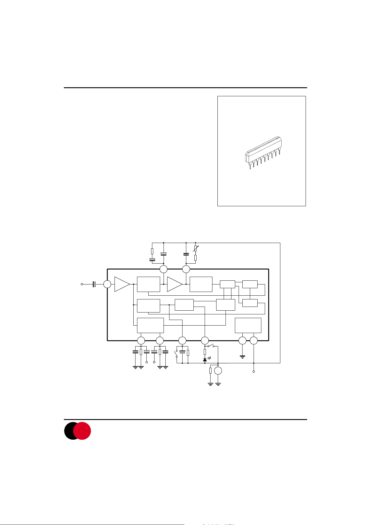
BLOCK DIAGRAM
SIP-9
Input
L.P.F-1
Contek
1 AF DC
Phase
Dector
Buffer
Decorder
L-CH OutputR-CH Output
2 4
Stereo
SW1
19kHz<90
Lamp
Trigger
19kHz<0
o
38kHz
L.P.F-2
Vcc
o
LED
Vcc
76kHz
38khz
check
SW2
FC
1/2 1/2
FM switch
GND
SW1 VCC
SW2 38KHz
1/2
Voltage
Regulator
356798
Vcc
CONTEK
Contek Microelectronics Co.,Ltd.
http://www.contek-ic.com E-mail:sales@contek-ic.com
1
Page 2
TA7343AP LINEAR INTEGRATED CIRCUIT
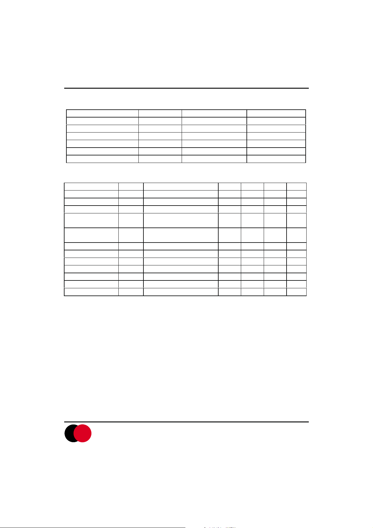
ABSOLUTE MAXIMUN RATING(Ta=25 C)
PARAMETER SYMBOL RATING UNIT
Supply Voltage VCC 12 V
Lamp Voltage VLAMP 16 V
Lamp Current (Continuous) ILAMP 20 mA
Power Dissipation PD 500 mW
Operating Temperature Range TOPR -20 - +70 C
Storage Temperature Range TSTG -40 - +125 C
ELECTRICAL CHARACTERISTICS(Ta=25 C,VCC=8V,f=1KHZ, unless otherwise specified)
PARAMETER SYMBOL TEST CONDITIONS MIN TYP MAX UNIT
Quiescent Circuit Current I
Maximum Input Voltage Vi(max) L+R=90%,P=10%, THD=1% 550 mV
Channel Separation CS L+R=180Mv, P=20mV 36 45 dB
Total Harmonic
Distortion (mono)
Total Harmonic
Distortion (Stereo)
Voltage Gain Gv Vi=200mV -2.0 0 +2.0 dB
Channel Balance CB Vi=200mV 0 1.5 dB
Lamp ON Level V
Lamp OFF Level V
Lamp Hysteresis HY 3 mV
Carrier Leakage Vleak 19kHz, L+R=180mV 34 dB
CCQ
THD1 Vi=200mV 0.08 0.3 %
THD2 L+R=1800mV, P=20mV 0.08 %
L(ON)
L(OFF)
Vi=0 11 18 mA
pilot only 9 15 mV
pilot only 2 6 mV
38kHz, P=20mV 42 dB
CONTEK
Contek Microelectronics Co.,Ltd.
http://www.contek-ic.com E-mail:sales@contek-ic.com
2
Page 3

TA7343AP LINEAR INTEGRATED CIRCUIT
TEST CIRCUIT
APPLICATION INFORMATION (refer to test circuits)
External Components
1.) Input coupling capacitor(C1)
The recommended value is 10 mF. If smaller vlaues than 10WF are used, low frequency separation will worsens,
and is larger values are used, POP noise occurs strongly.
2.) Low Pass Filter (C2,C1,R1)
This is the low pass filter fr the PLL, which is determined the capture range and THD at low frequency.
3.) VCO network (C4,R2,R7)
The VCO free running frequency is adjusted by connecting a frequency counter to monitor the 38kHz output of
Pin6.
4.) Decoder output (Pin8,9)
These components provide Right and Left channel output load circuits. The recommended circuits as follows:
CONTEK
Contek Microelectronics Co.,Ltd.
http://www.contek-ic.com E-mail:sales@contek-ic.com
3
Page 4

TA7343AP LINEAR INTEGRATED CIRCUIT
TYPICAL PERFORMANCE CHARACTERISTICS
CONTEK
Contek Microelectronics Co.,Ltd.
http://www.contek-ic.com E-mail:sales@contek-ic.com
4
 Loading...