

Page 1
TA31002 LINEAR INTEGRATED CIRCUIT
TELEPHONE TONE RINGER
DESCRIPTION
The Contek TA31002 is a bipolar integrated circuit
designed for telephone bell replacement. It can also be
used as alarms or other alerting devices.
FEATURES
*Current consumption is small. (at no-load)
*Package is compaction. (DIP-8 pin)
*Oscillation frequency is variable.
*Built-in threshold circuits prevent false triggering due
to power noise as well as chirps due to rotary dial.
*Few external componens.
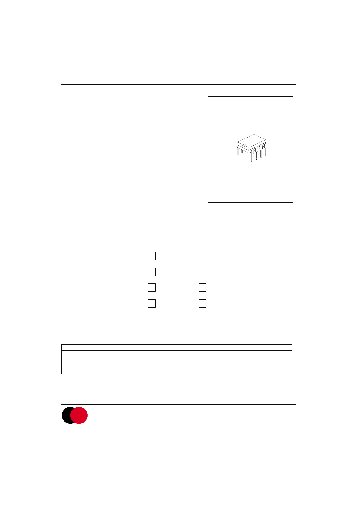
DIP-8
PIN CONFIGURATIONS
Vcc
RSL
LowFreq.
TimeConstant
LowFreq.
TimeConstant
1
2
Contek
3
4
Output
8
HighFreq.
7
TimeConstant
HighFreq.
6
TimeConstant
GND
5
ABSOLUTE MAXIMUM RATINGS (Ta=25 C )
Power Supply Voltage Vcc 30 V
Power Dissipation Pd 800 mW
Operating Temperature Topr -40 to 85
Storage Temperature Tstg -55 to 150
PARAMETER SYMBOL VALUE UNIT
Contek Microelectronics Co.,Ltd.
CONTEK
http://www.contek-ic.com E-mail:sales@contek-ic.com
C
C
1
Page 2
TA31002 LINEAR INTEGRATED CIRCUIT
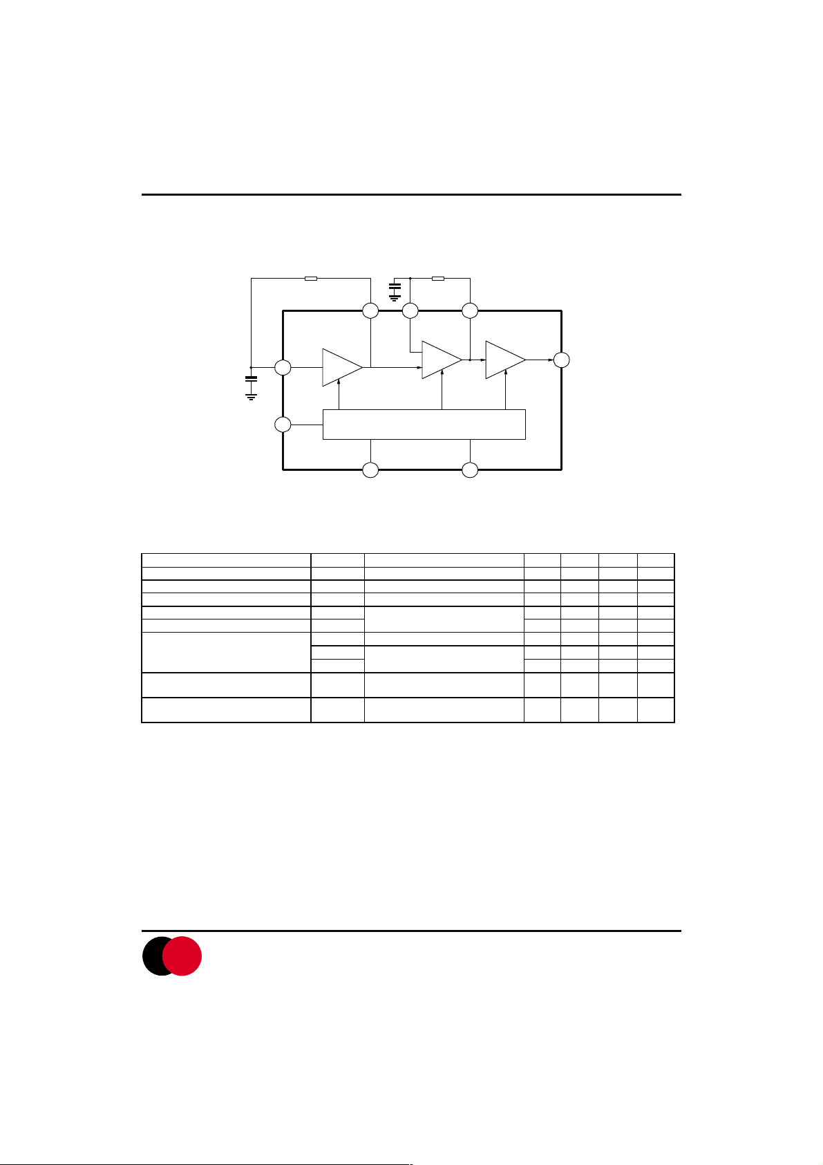
BLOCK DIAGRAM
R1
C2
R2
674
Contek
C1
3
1
LOW
OSC
POWER SUPPLY (WITH HYSTERESIS)
5 2
Note:R1,R2,C1 and C2 are partsexternally mounted
HIGH
OSC
AMP
8
OUTPUT
ELECTRICAL CHARACTERISTICS( Ta=25 C )
(All voltage referenced to GND unless otherwise specified)
Operating Voltage Vopr 29 V
Initiation Supply Voltage Vsi (note 1) 17 19 21 V
Sustaining Supply Voltage Vsus (note 2) 10.5 12 - V
Initiation Current Consumption Isi No-Load 1.4 3.3 4.2 mA
Sustaining Current Consumption Isus 0.7 1.4 2.5 mA
Oscillation Frequency (not3) fH1
Output Voltage H Level VOH Vcc=24V,VOH=-10mA
Output Voltage L Level VOL Vcc=24V,VOL=10mA
PARAMETER SYMBOL TEST CONDITIONS MIN TYP MAX UNIT
fL
fH2 576 640 703 Hz
C1=0.47mF,R1=165k W
C2=6800pF,R2=191k W
PIN7=GND
PIN7=7V
91011Hz
461 512 563 Hz
20.0 21.5 22.5 V
0.7 1.0 2.0 V
*NOTE : 1. Initiation supply voltage ( Vsi) is a supply voltage required to start oscillation of the tone ringer.
2. Sustaining supply voltage (Vsus) is a supply voltage required to maintain oscillation of the tone ringer.
3. Oscillation frequency is determined by the following equations 1,2,and 3.
(1) fL=1/1.234 R1 C1 (Hz) ; (2)fH1=1/1.515 R2 C2 (Hz); (3)fH2=1.24 fH1(Hz)
Contek Microelectronics Co.,Ltd.
CONTEK
http://www.contek-ic.com E-mail:sales@contek-ic.com
2
Page 3
TA31002 LINEAR INTEGRATED CIRCUIT
APPLICATION NOTE
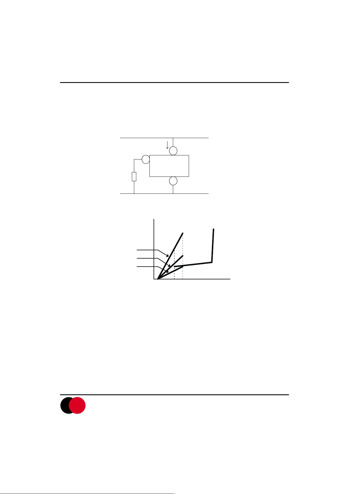
In theContek TA31002
RSL is connected to GND from PIN2 as shown in fig.1. Further, the initation current consumption(Isi) can be
changed by changing the value of RSL.
Fig.2 show the graph of Vs-Is characteristic at the time when RSL has been changed to three values. The Vs-Is
characteristic in TA31002 at the time when RSL=6.8k W coincides with that at the time when PIN2 of the TA31001 has
been used at an open state.
the initiation current consumption( Isi) can be changed by using the RSL terminal.The resistor
Vs
LS
1
2
RSL
Contek
TA31002
5
GND
FIG.1
CURRENT
CONSUMPTION
(mA)
5
Is
RSL=3.3kW
SL=6.8kW
R
SL=13kW
R
4
3
2
1
Vsus Vsi
10 20 30
Vs
SUPPLY VOLTAGE (V)
CONTEK
FIG.2
Contek Microelectronics Co.,Ltd.
http://www.contek-ic.com E-mail:sales@contek-ic.com
3
Page 4

TA31002 LINEAR INTEGRATED CIRCUIT
APPLICATION CIRCUIT
TIP
2KW
1 mF/250V
RING
104B42
C4
15mF/35V
+
-
D5Z27
R
R1
0.22mF
1
SL
2
Contek
TA31002
3
4
8
7
R2
6
C2
5
61W
SP
fL=1/1.234R1*C1
fH1=1/1.515R2*C2
fH2=1.24fH1
when:
R1=165KW R2=191K W
C1=0.47mF/16V C2=0.0068 mF/16V
fL@10Hz fH1 @500Hz fH2 @630Hz
Contek Microelectronics Co.,Ltd.
C1
15kW
1300:8W
4
CONTEK
http://www.contek-ic.com E-mail:sales@contek-ic.com
 Loading...