

Page 1

T-51440GL070HU-FW-AC OPTREX CORPORATION Page 1/27
OPTREX
Type No.
*******
June 20, 2002
Final Revision
First Edition
Checked by Engineering
Checked by Quality Assurance
Approved by Production
Drawn by Engineering
LCD Module Specification
T-51440GL070HU-FW-AC
Table of Contents
1. Application...........................................................................................2
2. Mechanical Specification .....................................................................2
3. Absolute Maximum Ratings................................................................3
4. Environment Condition........................................................................3
5. Optical Characteristics.........................................................................4
6. Electrical Characteristics...................................................................10
7. Product Standard................................................................................19
8. Reliability Test...................................................................................22
9. Code System of Production Lot........................................................24
10. Packing Specification .........................................................................25
11. Product handling Cautions................................................................ 26
12. Condition for Guarantee....................................................................27
Revision History
Rev. Date Page Comment
Page 2

T-51440GL070HU-FW-AC OPTREX CORPORATION Page 2/27
OPTREX
1.Application
This specification applies to 7.0” color TFT -LCD module (T-51440GL070HU-FW-AC).
The applications of the panel are for automotive entertainment and car navigation.
2.Mechanical Specifications
Screen Size : 7 inches (18cm) diagonal
Display Mode : Normally White
Driving Method : a-Si TFT active matrix format
Line Scan/non -interlace Reverse Horizontal Line
Composition : TFT Cell, Driver IC, Timing controller IC, Backlight unit, Inverter
DC/DC Converter, and Video circuit
Input Power Supply : +8V-16V(DC)
Input Signal : Composite Video Signal (NTSC/PAL) or
Specific Analog RGB signal (NTSC/PAL) + Composite or Separate
Synchronized signal
Output Signal : Horizontal/Vertical Synchronized signal (negative)
Resolution : 480(W) x 234(H)
Dot Resolution : 1440(W) x 234(H)
Dot Pitch : 0.3210(W) x 0.3720(H) mm
Pixel Configuration : RGB Stripe
Active Area : 154.08(W) x 87.048(H) mm
Backlight : Triple wavelength L-shaped Cold Cathode Fluorescent Lamp, Dimming
Ratio 1-100%
Viewing Direction : 12 O’clock (Maximum Contrast)
Surface Treatment : AGLR Coating (Low Reflectance)
Outer Dimension : 164.9(W) x 101.9(H) x 23.1(D) mm
Weight : TBD g max.
Attached Drawing : Dimensional Outline UE-210547-00
Page 3

T-51440GL070HU-FW-AC OPTREX CORPORATION Page 3/27
OPTREX
3.Absolute Maximum Ratings
Item Symbol Conditions Min. Max. Unit
Video Circuit VPW Vss–0.2 16.0 V
Power
Supply
Backlight VBL
Ta=25±5?
VSS=0V
Vss–0.2 16.0 V
Composite Video VIDEO
-
1.5 V
P-P
Analog RGB R,G,B
-
1.5 V
P-P
Synchronous
Signals
VSY,HSY – 1.5 V
P-P
Chroma Signal CYSYNC
Ta=25±5?
75O
VPW=VBL=+12.0V
– 1.5 V
P-P
Adjustment
Signals
COLOR,
BRT,CONT,
TINT,DIM
Vss–0.3
VDD+0.3
V
Input
Signal
Switching
Signals
U/D,R/L,
MOD1~3,
N/P,R/CMP,
YC/CMP
Ta=25±5?
Vss=0V
VPW=VBL=+12.0V
Vss–0.3
VDD+0.3
V
Storage Temperature T
stg
-
–40 +85
?
Operating Temperature T
opr
-
–30 +85
?
Note: Absolute maximum ratings should not exceed the limit anytime. If the product
exceeds the limit, it may cause damage. Please be cautious to the changes in supply voltage,
connection parts, surge of signals and ambient temperature.
4.Operating Conditions
Item Conditions Tmperature Range
Remark
LCD Module
w/Backlight
Ambient Temperature
(Panel Surface)
–30~85?
(
–30~85?)
Note4-1,4-2
Operating
Temperature Range
LCD Panel Surface Temperature –30~75?
LCD Module
w/Backlight
Surface Temperature –40~85?
Note4-3
Storage
Temperature Range
LCD Panel Surface Temperature –40~85?
Note4-1: Operating temperature range defines the operation only and the contrast, response time and
other display optical characteristics are set at Ta=+25?.
Note4-2: Panel surface temperature indicates the temperature of the backlight panel surface on the five
points from the four corners and the center. Also note that the panel temperature of backlight
side is 10?(reference value) higher than the other side.
Note4-3: Backlight is not activated.
Page 4

T-51440GL070HU-FW-AC OPTREX CORPORATION Page 4/27
OPTREX
5.Optical Specifications
Conditions Standard Value
Item Symbol
? f C
Min. Typ. Max.
Unit
Method of
Measure
Remark
(1)Brightness
B
0
°
0°
-
(400)
-
Cd/m2
Note5-1
(2)Contrast CR
Optimum
Viewing
60 150
-
-
X
0
°
0° 0.265 0.305 0.345
-
(3)White Chromaticity
Y
0
°
0° 0.300 0.340 0.380
-
(Fig.5-1)
(4)Brightness Uniformity
-
0
°
0° 0.7
-
-
-
(Fig.5-2)
Up
?
U
-
0° ?10
-
(60)
-
Degree
(5)Vertical
Viewing Angle
Down
?
D
-
0° ?10
-
(30)
-
Degree
Left
F
L
0
° - ?
10
-
(60)
-
Degree
(6)Horizontal
Viewing Angle
Right
f
R
0
° - ?
10
-
(60)
-
Degree
(Fig.5-3)
Rise
t r
0
°
0°
-
TBD TBD ms (7)Response
Time Decay
t d
0
°
0°
-
TBD TBD Ms
(Fig.5-4)
Note5-1:Under the condition of tube current 6.0mA
?
Conditions for Measuring
?
Environment: Dark room with no light or close to no light.
?
Temperature:
25±5?
?
Humidity:
40~ 70%RH
?
After backlight has been lit more then 30 minutes, driving voltage is set for optimal contrast to
measure center of display.
?
Measure by the specified inverter or similar product.
?
Optimal viewing angle (The angle with best contrast)
12 O’clock
Page 5

T-51440GL070HU-FW-AC OPTREX CORPORATION Page 5/27
OPTREX
(Fig.
5-1)
?
Method of Brightness Measurement
(1)
Measuring Device
TOPCON BM-7? Measuring Field:1°
(2)
Measuring Point
Center of Display
? =0°?f=0°
On condition
? :
A vertical angle from measuring direction to perpendicular.
f :
A horizontal angle from measuring direction to perpendicular.
(3)
Method of Measuring
Apply signal voltage (displayed in white) to maximize brightness and measure brightness B (cd/m2).
The distance between BM-7’s front lens to surface panel is 500mm.
Measured after backlight has been lit for more than 30 minutes.
?
Method of Contrast Measurement
(1)
Measuring Device
TOPCON BM-7? Measuring Field:1°
(2)
Measuring Point
Center of display: same as Method of Brightness Measurement
(3)
Method of Measuring
·
Set LCD module to
? =0°?f=0°
.
·
Change signal voltage to measure maximum brightness Y1 and minimum brightness Y2.
·
Contrast is derived from CR=Y1/Y2.
LCD Module
Distance
:500mm
TOPCON
BM-7
Center
(Pixel)
(X,Y)=
(240,117)
Page 6

T-51440GL070HU-FW-AC OPTREX CORPORATION Page 6/27
OPTREX
(Fig.
5-2)
?
Definition of Brightness Uniformity
Definition is calculated from the four points (S0-S4) on the diagram below.
Minimum Value of S1-S4
Standard Value of Brightness Uniformity=
S0
S1
S2
S3
S4
S0
20mm
20mm
20mm 20mm
Page 7

T-51440GL070HU-FW-AC OPTREX CORPORATION Page 7/27
OPTREX
(Fig.
5-3)
?
Method of Viewing Angle Measurement
(1)
Measuring Device
TOPCON BM-7? Measuring Field:1°
(2)
Measuring Point
Center of display : Same as Method of Brightness Measurement
(3)
Angle of Measuring
? :
An angle vertical to perpendicular line from the viewing direction.
F :
An angle horizontal to perpendicular from the viewing direction.
(4)
Method of Measuring
Set rotation table to
f =0°
and set BM-7 to contrast 10 to measure angle±? for left and right
direction of horizontal viewing anglef. Also set rotation table to
f =90°
and set BM-7 to
contrast 10 to measure angle±?for up and down direction of vertical viewing angle ?.
f
Rotation Table
(θ,φ)
TOPCON BM-7
Comp
uter
Waveform Generator
LCD
Temperature
Control Unit &
?
Page 8

T-51440GL070HU-FW-AC OPTREX CORPORATION Page 8/27
OPTREX
(
Fig.
5-4)
?
Measuring Response Time
(1)
Measuring Device
TOPCON BM-7? Measuring Field:1°
Tektronix Digital Oscilloscope
(2)
Measuring Point
Center of display, same as Method of Brightness Measurement
(3)
Method of Measuring
·
Set LCD panel to
? =0°
,and
f =0°
.
·
Input white?black?white to display by switching signal voltage.
·
If the luminance is 0% and 100% immediately before the change of signal voltage, then
t r
is
optical response time during the change from 90% to 10% immediately after rise of signal voltage,
and
t d
is optical response time during the change from 10% to 90% immediately after decay of
signal voltage.
White Black White
100%
90%
10%
0%
tr
td
Brightness
Page 9

T-51440GL070HU-FW-AC OPTREX CORPORATION Page 9/27
OPTREX
6. Electrical Characteristics
6.1 Recommended Operating Conditions
(Ta=25±5? ? Vss=0V)
Item
Symbol Condition Min. Typ. Max. Unit
System VPW 8.0 12.0 16.0 V Power
Supply
Backlight VBL 8.0 12.0 16.0 V
Composite Video VIDEO 1.0 Vp-p
Analog RGB R,G,B 0.7 Vp-p
Chroma Signal YCSYNC 1.0 Vp-p
Synchronous
Signals
HSY,VSY
75O
0.7 Vp-p
Brightness BRT 2.6 V
Tint TINT 1.0 2.7 V
Color COLOR 2.5 V
Contrast CONT 2.5 V
Backlight DIM 1 100 %
H level 3.0 3.6
Input
Signals
Select Signals
MOD1~3,N/P
U/D,R/CMP
R/L,YC/CMP
L level 0 0.8
V
f
VDN
57.14 59.939 62.86 Hz
f
HDN
NTSC
15.00 15.734 16.50 KHz
f
VDP
48.64 50.00 51.20 Hz
Synchronous Frequency
f
HDP
PAL
15.20 15.625 16.00 KHz
Note: Recommended Operating Conditions defines the guaranteed range of operation and it is out of guarantee
if the product exceeds the range even if within the range of Item3.Absolute Maximum Ratings.
Please use within the range of Recommended Operating Conditions.
6.2 Pixel Alignment
RG B R GB R GB
RG B R GB R GB
RG B
RG BRG B
GB
RG B R GB R GB
RG B R GB R GB
RG B
RG BRG B
RG B
RG B R GB R GB
RG B R GB R GB
RG B
RG BGB
RG B
RG B R GB R GB RGB
RG B R GB R GB
R
R
R
RG
R
B
Page 10

T-51440GL070HU-FW-AC OPTREX CORPORATION Page 10/27
OPTREX
6.3 I/O Terminal Descriptions
No. Symbol
Level
Function
I/O Remark
1 VDD
?
Power Supply
(+5V) Output
2 COLOR
?
Color Adjustment
(0~ 5V)
Input
3 BRT ? Brightness Adjustment
(0~ 5V)
Input
4 CONT
?
Contrast Adjustment
(0~ 5V)
Input
5 VIDEO ? Composite Video Signal Input
(1.0V
P-P
,75O )
Input
6 Vss
?
Signal Ground
?
7 Vss ? Backlight Ground ?
8 Vss
?
Backlight Ground
?
9 VBL ? Power Supply for Backlight
(+8~ 16V)
Input
10 VBL
?
Power Supply for Backlight
(+8~ 16V)
Input
11 U/D
H / L Up/Down Scanning Direction
(Open:Down to Up, GND:Up to Down)
Input
12 R/L H / L
Left/Right Scanning Direction
(Open: Left to Right, GND: Right to Left)
Input
13 DIM
?
Backlight Dimming
(1~ 100% Adjustable)
Input
14 MOD1 H / L Display Mode 1 Input
15 MOD2 H / L Display Mode 2 Input
16 MOD3 H / L Display Mode 3 Input
17 N/P H / L NTSC/PAL Select
(Open : NTSC, GND : PAL)
Input
18 TINT
?
Tint Adjustment
(1~ 5V)
Input
19 R/CMP H / L
RGB/Composite Select
(Open: RGB, GND:Composite)
Input
20 YC/CMP H / L
Synchronous Signal Select
(Open: YC Separate, GND: Composite)
Input
21 YCSYNC
?
Chroma Signal
(0.7V
P-P
,75O )
Input
22 VSY ? Vertical Sync.
(0.7V
P-P
,75O , Active Low)
Input
23 HSY
?
Horizontal Sync.
(0.7V
P-P
,75O , Active low)
Input
24 Vss
?
Signal Ground
?
25 G
?
Green Color Video Signal
(1.0V
P-P
,75O )
Input
26 B
?
Blue Color Video Signal
(1.0V
P-P
,75O )
Input
27 R
?
Red Color Video Signal
(1.0V
P-P
,75O )
Input
28 VPW ? System Power Supply
(+8~ 16V)
Input
29 VSYO
?
Vertical Sync.Output
(0.7V
P-P
,75O,Active Low)
Output
30 HSYO
?
Horizontal Sync.Output
(0.7V
P-P
,75O ,Active Low)
Output
Mating Connector : SHDR-30V -S-B (JST)
Page 11

T-51440GL070HU-FW-AC OPTREX CORPORATION Page 11/27
OPTREX
6.4 Block Diagram
OEV
FX
7 inch Wide TFT
LCD Module
VBL
DIM
V
COM
Video Controller
Timing
Controller
Inverter
COLOR
VSY
HSY
R/CMP
YCSYNC
U/D
YC/CMP
VIDEO
R,G,B
MOD1~3
CLK
OE
R/L
BRT
HSYO
VSYO
CONT
TINT
N/P
Brightness
Control
DC/DC
Converter
+18.5V
-12.0V
+5V
+3.3V
+3.3V +5V
-5V +7V
V
PW
Dip SW
HOT
GND
Page 12

T-51440GL070HU-FW-AC OPTREX CORPORATION Page 12/27
OPTREX
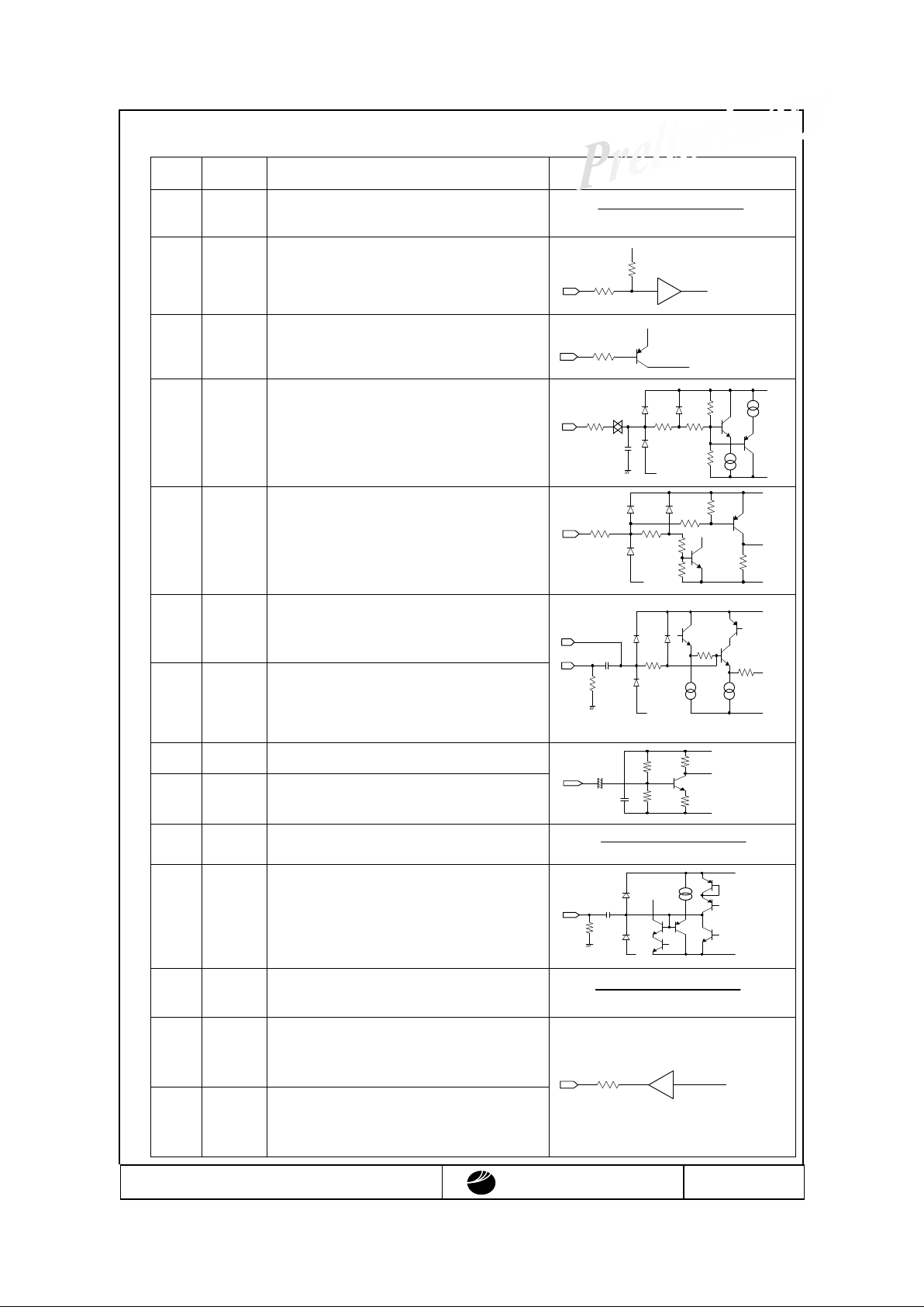
6.5 Signal Definition
Pin No. Symbol Function I/O Intermal Equivalent Circuit
1 VDD 5V output terminal
Please use this for each adjustable
terminal (2 ~ 4, 18 pin)
Output Current(Idd) = Less than 10mA
2 COLOR Color adjustment input terminal.
Can be selected to change anywhere
between 0 ~ 5V.
3 BRT Brightness Adjustment for RGB signal.
Can be selected to change anywhere
between 0 ~ 5V.
4 CONT Contrast adjustment terminal.
Can be selected to change anywhere
between 0 ~ 5V.
5 VIDEO Composite video signal input terminal.
Please use standard input level 1 Vp-p
of composite video signal. When using
composite video input signal fix
YCSYNC(21pin) to GND .
6 Vss Signal Ground terminal.
Connect to GND.
7 Vss Backlight grounding terminal.
Connect to GND.
8 Vss Backlight grounding terminal.
Connect to GND.
9 VBL Power supply input terminal for ba
cklight.
Use standard 12V.
10 VBL
Power supply input terminal for backlight.
Use standard 12V.
11 U/D Up/Down scanning direction select
terminal.
When open, it will scan down to up.
When connected to GND, it will scan
up to down.
12 R/L Left/Right scanning direction select
terminal.
When open, it will scan left to right.
When connected to GND, it will scan
right to left.
40k
40k
60k
24k200100
-5V
+5V
GND
10k
75k200
100
-5V
+5V
GND
+5V
50k
40k
20k
200100
-5V
GND
+5V
-5V
1uF
GND
75
100
Page 13
T-51440GL070HU-FW-AC OPTREX CORPORATION Page 13/27
OPTREX
Pin No.
Symbol Function I/O Intermal Equivalent Circuit
13 DIM Backlight Dimming Terminal.
Input 3.3V square wave PWM format
14
15
16
MOD 1
MOD 2
MOD 3
Display mode select input terminal
See Table 6.1
17 N/P NTSC/PAL select terminal.
Open : NTSC
GND : PAL
18 TINT Tint adjustment input terminal.
Can be selected between 1~5V
19 R/CMP Video signal input select terminal.
Open: Analog RGB
GND: Composite Video
20 YC/CMP Synchronous signal input select terminal.
Open: YC seperate input
GND: Composite
21 YCSYNC Chroma input terminal.
Use Chroma signal 0.7Vp-p.
When using composite video, connect to
GND.
22 VSY Vertical synchronous signal input terminal.
23 HSY Horizontal synchronous signal input terminal.
24 Vss Signal Ground terminal.
Connect to GND.
25
26
27
G
B
R
Analog RGB signal input terminal.
Use Analog RGB signal standard level
0.7Vp-p.
28 PWR System power supply input terminal.
Use standard 12V.
29 VSYO Vertical synchronous signal output terminal.
Please use for UOS(under on screen) to adjust
the screen position.
30 HSYO Horizontal synchronous signal output
terminal.
Please use for UOS(under on screen) to adjust
the screen position.
22k
+3.3V
100
+3.3V
22k
40k
25k
35k200
100
-5V
+5V
GND
36k
4.7k
30k
1k
200100
-5V
+5V
GND
4.7k
5k
0.1uF 200
75
-5V
+5V
GND
YC/CMP
YCSYNC
22k
2k
10uF
22k
100
0.1uF
+3.3V
GND
+
0.1uF
75
-5V
+5V
GND
100
Page 14

T-51440GL070HU-FW-AC OPTREX CORPORATION Page 14/27
OPTREX
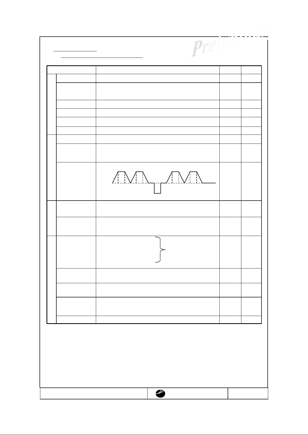
Table 6.1 : Display Mode
Mode
Display Image
(4:3 Signal Input)
MOD1
(14pin)
MOD2
(15pin)
MOD3
(16pin)
Remark
Full
GND GND GND
Input Signal is displayed fully
on screen.
Normal Center
OPEN GND GND
4:3 Image displayed in center
of
display.
Wide
GND OPEN GND
4:3 Signal has been extended
sideways from center of
display.
Zoom 1
OPEN OPEN GND
Display is fixed on top and
then
zoomed.
Zoom 2
GND GND OPEN
The time for gate is adjusted
from Zoom1 mode.
Normal Left
OPEN GND OPEN
4:3 image shifted to left.
Normal Right
GND OPEN OPEN
4:3 image shifted to right.
Unfixed
OPEN OPEN OPEN
Unfixed
Page 15

T-51440GL070HU-FW-AC OPTREX CORPORATION Page 15/27
OPTREX
6.6 Timing specification (Analog RGB)
Fig.6-1 Full/Wide/Zoom1,2 mode
Note: Display mode and DipSW setting can change non-display lines and display lines.
Fig6-2 4:3 mode (Center/Right/Left)
Note: Normal left/right has same value as Normal center values as above.
*( ) values are for PAL mode
Dot clock : 9.59MHz (9.53MHz)
R,G,B 3Sub-pixles =1clock
262.5 Line
(312.5Line)
Non-display Line
234
Line
(281
Line
50.01µs(50.36µs)
DipSW
Selectabl
e
63.56µs(64.00µs)
VSY
HSY
262.5 Line
(312.5 Line)
Non-display line
234
Line
(281
Line)
50.01µs(50.36µs)
DipSW
S
electable
63.56µs(64.00µs)
VSY
HSY
* ( ) values are for PAL mode
Dot clock : 7.20MHz (7.15MHz)
R,G,B 3sub-pixels =1clock
Page 16

T-51440GL070HU-FW-AC OPTREX CORPORATION Page 16/27
OPTREX
Fig. 6-3 (Horizontal Timing (NTSC/PAL)
Note : All values are set at typical.
Values within ( ) are values for PAL mode.
Fh=15.734(15.625) kHz
HSY
4.7µs
R,G,B
1.0Vp-p
0.7Vp-p
1 LINE=63.56(64.00)µs
50.01(50.36)µs
Display Area
DipSW
Selectable
Page 17

T-51440GL070HU-FW-AC OPTREX CORPORATION Page 17/27
OPTREX
Fig.6-4 Vertical Timing (NTSC: Full/4:3mode)
Note: Wide/Zoom mode has different starting location
525 1 2
11
8
4
30
10
Display Area
0.7
Vp-p
DipSW Selectable
524
5 6 7
3
9
20
29
26 22
28
23 24 25
21
27
Display Area
262 263 264
273
270
266
272 274
267 268 269
265
271
285
275
255
245 246
284
254
0.7
Vp-p
DipSW Selectable
DipSW Selectable
0.7
Vp-p
1.0 Vp-p
VSY
Line No.
R,G,B
HSY
VSY
Line No.
HSY
R,G,B
(12 ~ 19H)
Page 18

T-51440GL070HU-FW-AC OPTREX CORPORATION Page 18/27
OPTREX
6.7 Video Board Adjustment
6.7.1
Dip Switch (SW 1,2)
Dip Switch Number Contents Remark
Horizontal Display Starting Position Adjust(From
HSY
)
Vertical Display Starting Position Adjust(From VSY)
SW1
SW1-8:Display Image Adjustment Select
ON:Internal by Pots. OFF:External by level
Default Set
SW1-1 : ON
SW1-2 : OFF
SW1-3 : ON
SW1-4 : OFF
SW1-5 : OFF
SW1-6 : OFF
SW1-7 : OFF
SW1-8 : ON
SW2-1:ON(Default)
SW2-2:ON(Default)
SW2-3:UOS(Under On Screen) Display Select
ON:Active OFF:Non Active
SW2
SW2-4:Synchronous Signal Select
ON:Composite OFF:Analog RGB
Default Set
SW2-1 : ON
SW2-2 : ON
SW2-3 : OFF
SW2-4 : ON
6.7.2 Potentiometers for Display Image Adjustment
Symbol Contents Remark
VR301 TINT:Tint Adjustment
VR302 COLOR:Color Adjustment
VR305 CONT:Contrast Adjustment
VR312 BRT:Brightness Adjustment
ON ON ON
ON OFF OFF OFF OFF OFF
OFF ON ON OFF OFF ON
OFF ON OFF
ON OFF ON
ON ON OFF
12H(24H)
13H(25H)
14H(26H)
15H(27H)
16H(28H)
17H(29H)
18H(30H)
19H(31H)
SW1 7 6 5 Start Line=12H
ON ON ON
ON OFF OFF OFF OFF OFF
OFF ON ON OFF OFF ON
OFF ON OFF
ON OFF ON
ON ON OFF
7.3000uS(8.5000uS)
6.9875uS(8.1875uS)
6.6750uS(7.8750uS)
6.3625uS(7.5625uS)
6.0500uS(7.2500uS)
5.7375uS(6.9375uS)
5.4250uS(6.6250uS)
5.1125uS(6.3125uS)
SW1 4 3 2 1 Wait Time
ON ON ON
ON OFF OFF OFF OFF OFF
OFF ON ON OFF OFF ON
OFF ON OFF
ON OFF ON
ON ON OFF
4.8000uS(6.0000uS)
4.4875uS(5.6875uS)
4.1750uS(5.3750uS)
3.8625uS(5.0625uS)
3.5500uS(4.7500uS)
3.2375uS(4.4375uS)
2.9250uS(4.1250uS)
2.6125uS(3.8125uS)
ON
ON ON OFF OFF
OFF
OFF ON OFF OFF
OFF ON
ON OFF
ON
ON
( ) values are for PAL mode, at zoom add31H(35H)
( ) values are for PAL mode, other values at side black
Page 19

T-51440GL070HU-FW-AC OPTREX CORPORATION Page 19/27
OPTREX
7.Product Standard
7.1.Mechanical Testing
7.1.1.External appearance
Inspection Area Item Criteria Remark
Surface
Linear
Scratches
Thickness
Disregard under 0.05mm
Between 0.05mm-0.15mm, total length must be within 50mm
Greater then 0.15mm is not acceptable
Surface
Sport
Scratches
Disregard under 1 sub-pixel
Penalized for 1-3 sub-pixels
Shall not exceed 3 sub-pixels
Back
Scratches
Observe from surface and judge based on criteria of surface
Chipped It must not influence surface
Dirt Must be removable
TFT Cell Section
Discoloration
No irregular discoloration on screen
Note1
Note2
Linear
Scratches
Thickness
Disregard under 3.0mm
Greater then 3.0mm must have less then 90mm total
Spot
Scratches
Diameter
Less then 3.0mmf,only 3 is allowed
Greater then 3.0mmf is not accepted
Dirt Must be removable
Deformation
Not allowed
Metal
Shield case
(Applies to all
surface)
Fingerprint
Remove as much as possible
Crack No crack or disconnection
Distortion No noticeable distortion
Note2
Input Output
Section
(FPC w/B/L Cable)
FPC tape The FPC should not be coming off for more then 10mm Note3
Note1: Cell section’s area subject to quality display area. Quality display area is specified in the external
appearance drawing.
Note2: If there are any other problems please follow “Precautions under operation”.
Note3: This is provisional standard and applies to limited sample (Optrex standards)
7.1.2.Dimensional Outline
All standards follow the measurement designated by the dimensional outline drawing.
Page 20

T-51440GL070HU-FW-AC OPTREX CORPORATION Page 20/27
OPTREX
7.2.
Quality of Display
7.2.1.Conditions for Common Inspection
Unless specified, the conditions below will be applied.
Ta=25±5
? ?
Humidity=65%?VPW=VBL=+12.0V?VSS=0V?Backlight inverter=Our standard
inverter or equivalent, measured after backlight bas been lit for more then 30 minutes.
7.2.2.Quality Display Standard and Criteria for Judgement
(A)Quality Display Standard
Item
Description Criteria
Line defect Black, white and colored line
Not
accepted
Quality
Display
Spot defect
Lighting irregularities due to sub-pixels by the TFT and CF.
White spots
:
Any pixel that can be seen through ND(Neutral Density)
filter when black signal(V
sig
=4V) is inputted under
specified condition.
Black sports:Any pixel that is below 50% of maximum luminance
when white signal(V
sig
=0V) is inputted.
Refer to
next
section
Note 2
Stain Luminance irregularities and discoloration spots.
Irregularity Same as stain with more area.
Line Same as stain but in linear shape.
Stripe Same as stain, but in arc, spirals, or moiré shape.
Quality
Screen
Reverse Others that are formed from concentration of irregular patterns.
Note 1,2
Note1: The quality of screen is set at V
sig
=0V(white),2V(middle),4V(black)screen display and it may not be
seen through 2.5% ND filter. However, for few exceptions, Sample under Optrex standard will be
used for inspection.
Note2: When questions arise concerning this specifications or new problems that are not specified, it will be
discussed for solution.
Page 21

T-51440GL070HU-FW-AC OPTREX CORPORATION Page 21/27
OPTREX
(B)
Spot Defect Inspection Standards and Criteria.
White spots inspection criteria
7.2.1.Include below with the common inspection condition
· Luminance: 200~ 250 [lx]
· Distance: 45~ 50 [cm] (Perpendicular from panel surface)
· Time: 5 [S] (After ND filter has been placed)
· Surface Brightness : 300~ 320 [cd/m2]
Standard
Type
Acceptable
No.
Criteria
Level 1
White Spots
0
Visible through 0.3%ND filter
Level 1-
2
White Spots
3
Visible through 1.0%ND filter, and not visible through 0.3%ND filter
Level 1-
3
White Spots
5
Visible through 2.5%ND filter, and not visible through 1.0%ND filter
Black spots
6
Any visible black spots on V
sig
=1V(All white cluster)
Total
7
Total white and black spots in level 1-3
Any spots that are not visible through 2.5% ND filters and not within level 1-3 is disregarded.
?
Density:
Only up to 2(white or black) are allowed for diameter withinf10mm.
If it is continuos, then continuos spot is applied.
?
Continuos spot :
Any spot that continues for more then 3 pixels is not acceptable.
For 2 continuos white spots, treat as one spot for the table above.
For 2 continuos black spots, treat as two spots for the table above.
For 2 continuos white and black spot, treat as one each.
?
White & black spot:
If the pixel holds both white and black spot (level 1-3), treat as white spot for the table above.
?
Foreign Substance(within Cell):
Foreign substance shall not be more then 3-pixel size.
If the size of substance is 2 to 3-pixel, then count as 2 in acceptable value.
If the size of substance is 1 to 2-pixel, then count as 2 in acceptable value.
If the size of substance is smaller then 1 pixel, then disregard.
Page 22
T-51440GL070HU-FW-AC OPTREX CORPORATION Page 22/27
OPTREX
8.Reliability Test
8.1.Mechanical and Environmental Test
Item Condition Test hour Remark
High temp operation
Ta=65±2?,45%RH Below
192 hrs Note1
High temp & high
humidity operation
Ta=65±2?,90±2%RH, No Condensation
192 hrs Note1
Low temp operation
Ta=-30±3?
192 hrs Note1
High temp storage
Ta=85±2?,45%RH below
192 hrs
Note1
Low temp storage Ta=-40
±3?
192 hrs Note1
Endurance
Light resistance Sunshine carbon arc Ta=63
±2?
360 hrs
Drastic temp change
-30?(60min)?25?(15min)?80?(60min), No electric path
20 cycle Note2
Condensation
-30?(30min non-operating),25?/95%RH(10min
operating)
Dried after specified cycle and confirm operation
10cycle
Heat
Humidity cycle
1cycle=48hrs non-operational
5cycle
Static resistance
C=200pF,R=0
O ,V=±
150V
3 discharge on electric and other terminal, non-operational
-
Electrical
Electric discharge
C=150pF,R=150
O ,V=±
15kV
Discharge ±chrages 5 times each on panel and earth, nonoperational
-
Vibration
5~10Hz,width 25mm
10~30Hz,3.7×9.8m/s2 X,Y,Z all dir
30~50Hz,1.6×9.8m/s2 8min×2sweep
50~80Hz,0.7×9.8m/s
2
non-operational
80~100Hz,0.3×9.8m/s2
All dir
96 hrs
Shock
980m/s
2
,
t=6ms,X,Y,Z all dir2,semi-sine-wave, non-
operational
-
Terminal durability
Apply 500g of weight perpendicular to end of terminal
Onon-operational
-
External durability
Apply pressure on the center of the screen by push/pull gauge.
head diameter isf12mm?pressured apply 5×9.8N(=5kgf)
once, non-opreatioal
-
Mechanical
Pressure resistance
5×10⁴ Pa(=0.5Pressure)?non-operational
2 hrs
Note 1: High temperature operation, high temperature & high humidity operation, low temperature operation,
high temperature storage and low temperature storage will test it’s ability for 1000 hours to confirm.
The deteriortion of plarizer is disregarded.
Note 2: Drastic tempertaure change test will continue the inspection under same condition consecutiely to
confirm it’s ability. Test will be done mounted in your request kit.
65?
25?
0?
2.5 2.5 2.5 2.5
2.5 2.5
2.5 2.5 2.5 2.5
3 3 3 3 3
8 hrs
90~ 95%RH
Page 23
T-51440GL070HU-FW-AC OPTREX CORPORATION Page 23/27
OPTREX
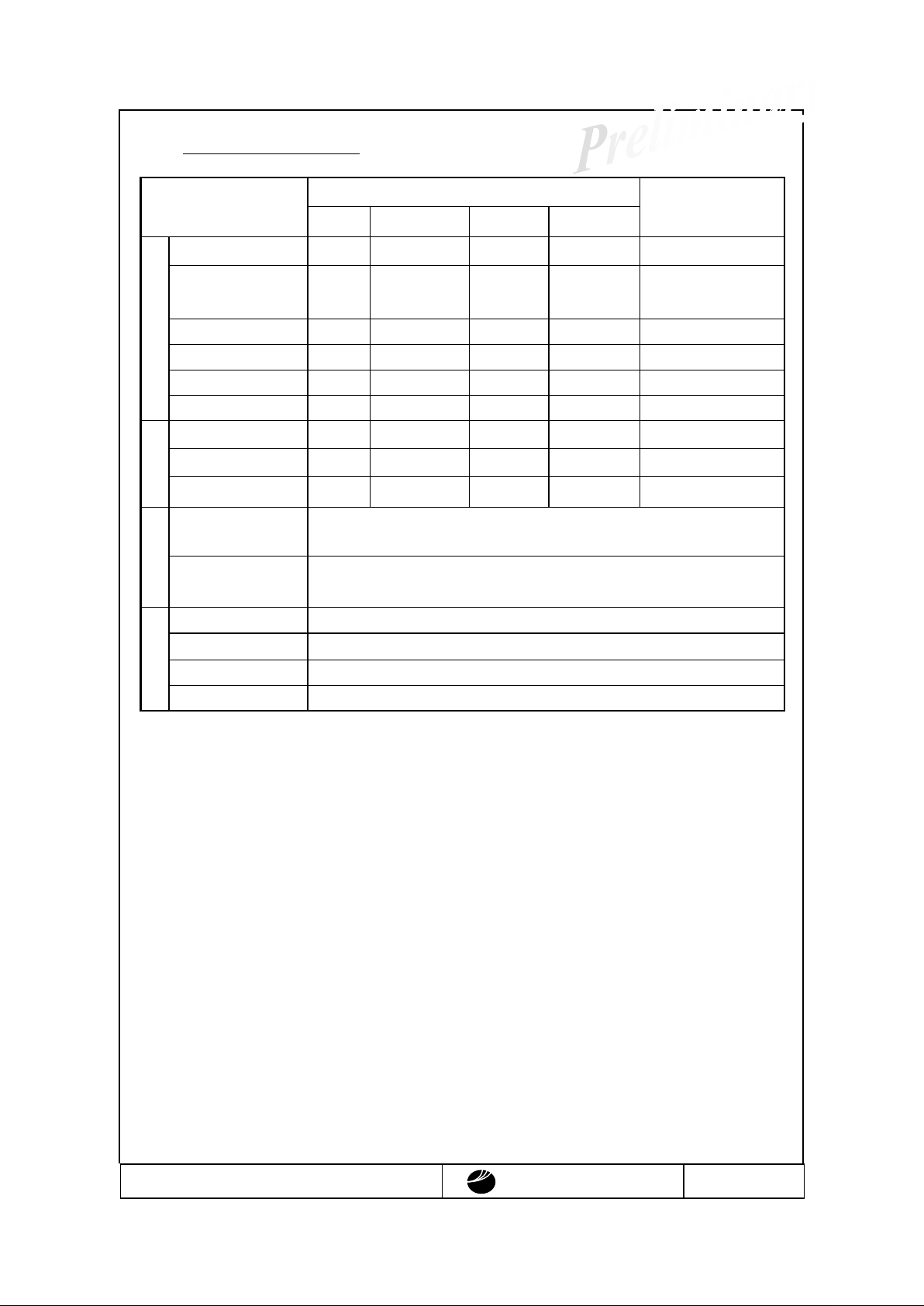
8.2.Reliability Test Standard
Optical & Electrical Characteristics
Item
Contrast
Surface luminance
Response
Circuit
Quality of Screen
High temp operation*
>30
within±20% within±20% Within+40%
Not to be conspicious
High temp & high humidity
operation*
>25
?
?
?
?
Low temp operation*
>30
?
?
?
?
High temp storage*
?
?
?
?
?
Low temp storage*
?
?
?
?
?
Endurance
Light resistance*
?
?
?
?
?
Drastic temp change*
?
?
?
?
?
Condensation?
>25
?
?
?
?
Heat
Temp.& Humidity cycle?
?
?
?
?
?
Static resistance
No abnormalities in system and display.
Electrical
Electric discharge
No damage should be done
Vibration
No abnormalities in system and display.
Shock
No abnormalities in system and display.
Exterior durability
No abnormalities in system and display.
Mechanical
Pressure durability
No abnormalities in system and display.
Note
: *
indicates that test was performed in room teperature, more then 2 hours after it was taken out from
chamber.
?indicates that test was performed after 24 hours after it has been taken out from chamber.
Luminance, circuit, response time changes are compared from the initial standard values.
Page 24

T-51440GL070HU-FW-AC OPTREX CORPORATION Page 24/27
OPTREX
9.Code System of Production Lot
9.1.Production Lot Number
Module’s production Lot Number will be indicated as below.
?
? ? ? ? ?
Factory Number (number)
Factory Code (Alphabet & Number)
Week of Manufacture
(1~ 5)
Month of Manufacture
(1~ 9,X,Y,Z)
Year of Manufacture(Lower 2 digits)
9.2.Type Number
The type number of module is specified on the back of module as follows;
T -51440GL070H U - FW- A-A
C
Silk Screen Print
9.3.Precautions under Operation
When questions arise concerning this specifcations or new problems not specified in this specifications
arise, problems related to the specification is to be discussed for solution.
Page 25
T-51440GL070HU-FW-AC OPTREX CORPORATION Page 25/27
OPTREX
10.Packing Specification
T B D
Page 26

T-51440GL070HU-FW-AC OPTREX CORPORATION Page 26/27
OPTREX
11.Product Handling Cautions
In order to use the products properly please note the following precautions.
1) For LCD screen
?
LCD particles used in LCD module is made into form of glass board. Do not apply any strong
physical shock.
If it cracks, handle with extra caution to avoid any harm.
?
The polarizer attached on the surface of LCD particles are composed by soft materials. Please do
not scratch them.
2) Handling LCD module (static electricity countermeasure)
?
Please ground all human bodies and electrical facilities. Also on the operation line, anti-static
electricity mat (rubber) is recommended to avoid electric shock in case of accident.
?
Working uniform should avoid synthetic fiber and recommend the use of cotton or non-electrical
conducting fiber.
?
When removing protective film from LCD panel, please remove it slowly to avoid development of
static electricity.
3) For Storing Single LCD module for long term
?
Do not store under high temperature and high humidity.
?
Do not expose the module to direct sunlight or intensive ultraviolet rays for many hours.
?
Avoid any force applied from external environment.
4) LCD module does not have circuit for over current protection. For in case of accident, please use
power supply with over current protection.
5) If LCD panel breaks, it is possible that the liquid crystal leaks from the panel. Avoid putting it into
eyes or mouth. When liquid crystal sticks on hands, clothes, or feet. Wash it out immediately with
soap.
6) When using product with metal holder, if metal holder and the body are not soldered, sooth electric
flow is not guaranteed. To secure the flows of electricity, please consult.
7) For products that requires the use of
CFL
?
On the connection of CFL cable more then 1000 v high voltage is applied. Please handle with
care to avoid any burn upon contact.
?
Please be careful if overcoat of CFL cable is in the status of abrasion by the contact with the system.
?
Continuous use of CFL at low temperature, will shorten longevity of CFL compared to it’s use at
room temperature.
8) For products that uses touch panel
?
Do not stack panel on top of each other. There may be possibility of harm caused by the edge of
panel.
?
Do not place any heavy objects above panel.
Page 27

T-51440GL070HU-FW-AC OPTREX CORPORATION Page 27/27
OPTREX
9) For product that uses COG, TAB, and COF
?
The back side of IC hip is exposed and has low intensity. Upon handling, do not apply powerful
pressure to the IC chip.
?
IC chip backside is exposed and should not be equipped with any setup that releases electrical
contact to prevent electrical damage. Also to prevent unintentional function by light and to keep
it’s electrical characteristics, set up to avoid exposure to light.
10) For product that uses FPC, heal seal and TAB
?
To maintain reliability, do not hold onto connection section.
Do not bend or pull lines with strong power. It could snap the lines.
12.Condition for Guarantee.
Our product is designed and manufactured by your specification requirement as a part for final electrical
products. We will guarantee the product has no sign of defect and meet all qualifications of your
request. However, if the final product was not for common household use, but instead used for medical,
nuclear controller, aviation, disaster prevention or any other products that require extreme reliability, we
can not be held responsible for any quality guarantee issue.
If the product was placed for any of the use above, we ask for revision on our contract for manufacturing
this product.
1) After delivery, any modification (including restructure and taking apart) of the product we can not
hold any responsibility for quality guarantee issue.
2) Any damage caused by the outside force, we can not hold any responsibility for quality guarantee
issue.
3) After completing all product inspection and after delivery from the factory, any static electricity
applied on product, we can not hold any responsibility for quality guarantee issue.
4) Upon using product with CFL, longevity and luminance may altar by the performance of inverter or
leakage. We can not hold any responsibility for quality guarantee issue by performance or
reliability of final product.
5)
Any product that uses our product within, we will not hold any responsibility for any problems that
has no relationship with the structure or performance of our product.
 Loading...