

Page 1
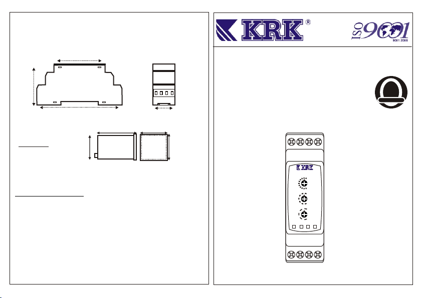
Dimensions
SZR M1
45mm
MULTI FUNCTIONAL TIMER
56mm
90mm
83 mm
KZR 48-M1
Technical Specifications:
Supply Voltage : SZR M1 :220 Vac ± %20, (L , N )
24 Vac/dc ±%10 ( N,B1 )
KZR 48-M1:220 Vac ± %20 ( L,N )
Adjustment Accuracy
Time Range
Functions Delay ON / Equal ON/OFF ON start Flasher
F2: F4:
Power Consumption
Ambiant Temperature
Contacts Type
Electrical Connections
: F1: F3:
45 mm
: ± %3
: 0,06 sec...30 hour
Delay OFF / Equal ON/OFF OFF start Flasher
: <= 3 W
: -5...+55 °C
: 10A, 250 Vac(Omron)
: PCB Connectors (2,5 mm2 )
22,5mm
48 mm
48 mm
SZR M1
KZR 48-M1
User Guide
3
2 1
SZR M1
.7
.5
.3
6h
60m
10m
60s
30s
F3
F2
F1
On Out
N
L1 B1
2
YEARS
GUARANTEED
1
Time
.01
30h
Rng
6s
F4
Func
OFF
Page 2
General Specifications
KZR M1 / SZR M1
Multi Functional Timer is microcontroller based and has 4 functions. Working functions,
time ranges and time adjustments can be done at front of the timer.
A ) Time Adjustment : This is a multiplier which multiplies the time range according to the
adjusted function. Multiplier is between 0,01 to 1. With this button you can divide time ranges
till 100 times.
B ) Time Range Adjustment : This for choosing the time ranges. Time adjustment are
between 6 seconds till 30 hours.
C ) Function Adjustment : This is for choosing appropriate function to your need. Relay
has 5 steps, four of them is for functions and one of them is to CUT relay output in every
condition.
OFF : It cuts relay output in every condition. Specially good for checking the system.
F1 : Delay ON Function: When relay is energised, ON led is lights, after adjusted time OUT
led is light .
F2 : Delay OFF Function: When relay is energised, ON led and OUT led is light on, after
adjusted time OUT led is off.
F3 : Equal Time ON Flasher Function: When relay is energised, ON led and OUT led is on,
after adjusted time OUT led is off, than again after same adjusted time OUT led is on, and
this continues in cycle.
F4 : Equal Time off Flasher Function: When relay is energised, ON led is on and OUT led is
off, after adjusted time OUT led is on, than after again same adjusted time OUT led is off, and
this continues in cycle.
Note: “On” and “Off” time ranges are equal for F3 and F4 functions.
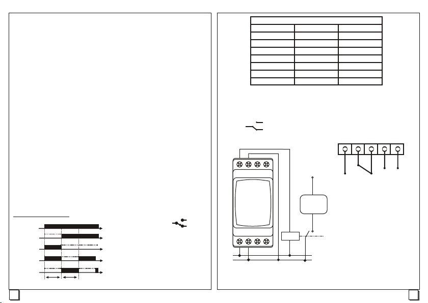
Function Schemes
U
on
F1
off
on
F2
off
on
F3
off
on
F4
off
Relay Contacts:
t: Adjusted Time
U: Supply Voltage
3
on
2
off
1
t t
2
Step
6 s
30 s
60 s
10 m
60 m
6 h
30 h
Connection Schemes
3
2
1
3
2 1
KZR M1
SZR M1
N
L B1
N
L
K 1
K 1
Time Range
Min. Multiplier =0,01
0,06 s
0,3 s
0,6 s
0,1 m
0,6 m
0,06 h
0,3 h
N
LOAD
Max. Multiplier =1
6 s
30 s
60 s
10 m
60 m
6 h
30 h
KZR 48-M1
2
1
Supply
Voltage
3
Relay
Output
3
 Loading...