

Page 1
COAXIAL
CABLE DRIVER
SY10EL89
FEATURES
■ 375ps propagation delay
■ 1.6V output swings
■ Internal 75KΩ input pull-down resistors
■ Available in 8-pin SOIC package
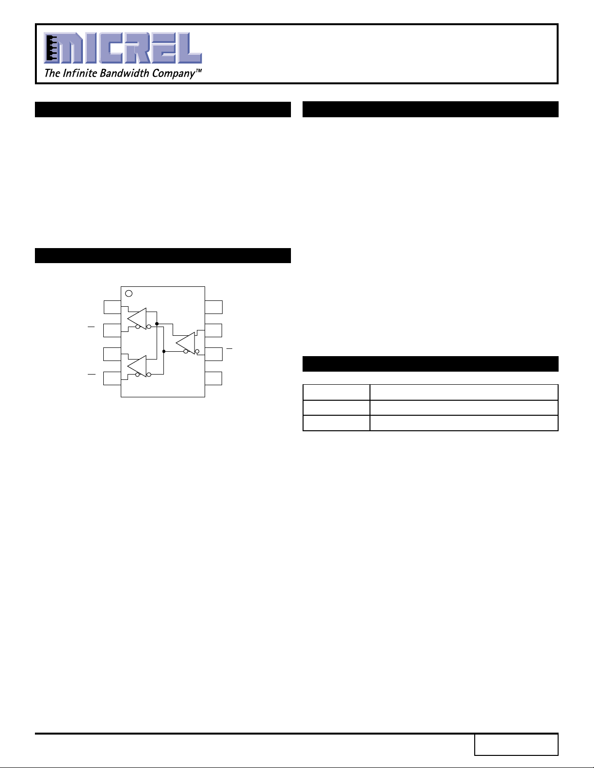
PIN CONFIGURATION/BLOCK DIAGRAM
1
0
Q
2
Q
0
3
Q
1
45
Q
1
SOIC
TOP VIEW
8
V
CC
7
D
D
6
V
EE
DESCRIPTION
The SY10EL89 is a differential fanout gate specifically
designed to drive coaxial cables. The device is especially
useful in Digital Video Broadcast applications. For this
application, since the system is polarity-free, each output
of the device can be used as an independent driver.
The driver boasts a voltage gain of approximately 40
and produces output swings twice as large as a standard
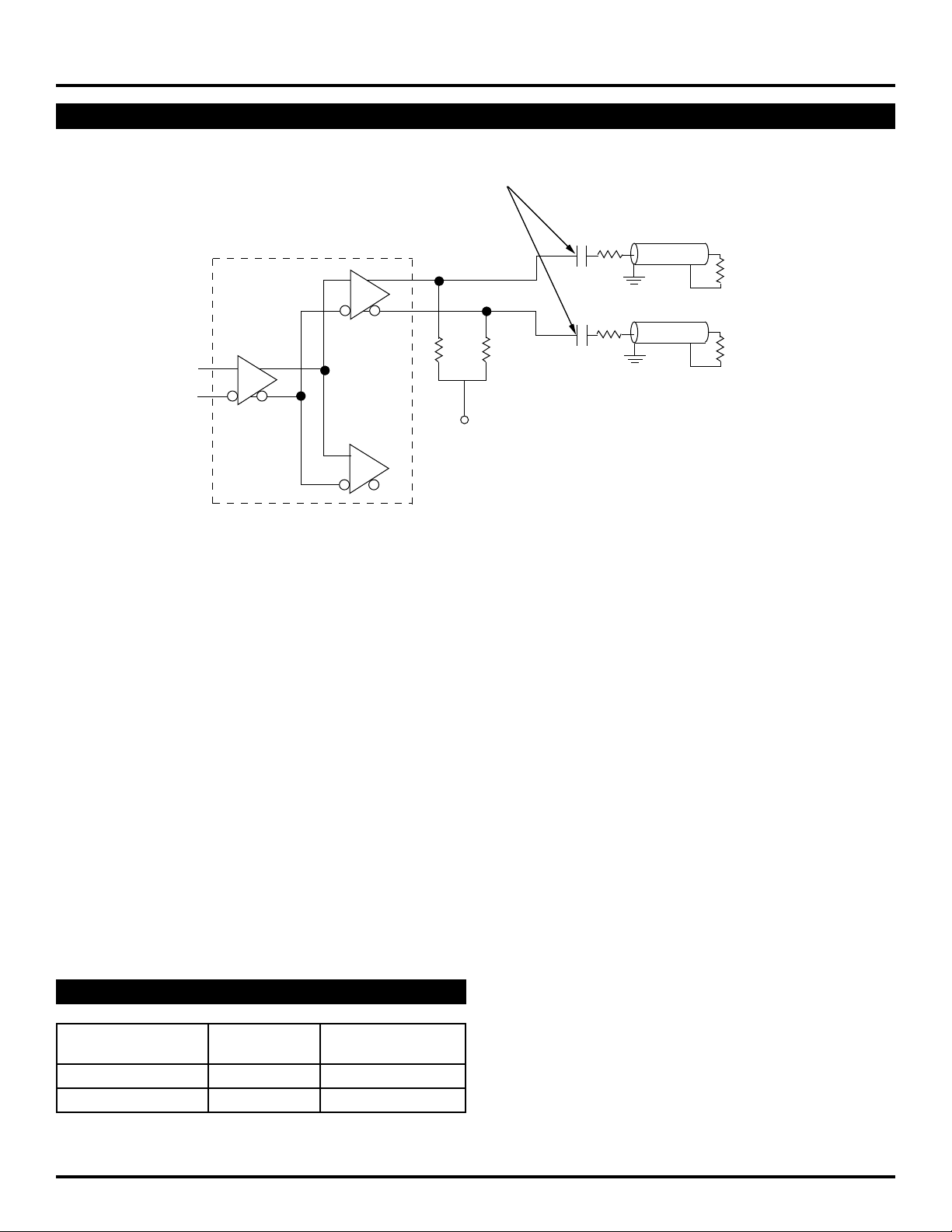
ECL output. When driving a coaxial cable, proper
termination is required at both ends of the line to minimize
signal loss. The 1.6V output swings allow for termination
at both ends of the cable while maintaining the required
800mV swing at the receiving end of the cable. Because
of the larger output swings, the device cannot be
terminated into the standard –2.0V. All of the DC
parameters are tested with a 50Ω to –3.0V load. The
driver accepts a standard differential ECL input and can
run off the Digital Video Broadcast standard –5.0V supply.
PIN NAMES
Pin Function
D Data Inputs
Q
0, Q1 Data Outputs
Rev.: E Amendment: /0
1
Issue Date: August, 1998
Page 2
Micrel
SY10EL89
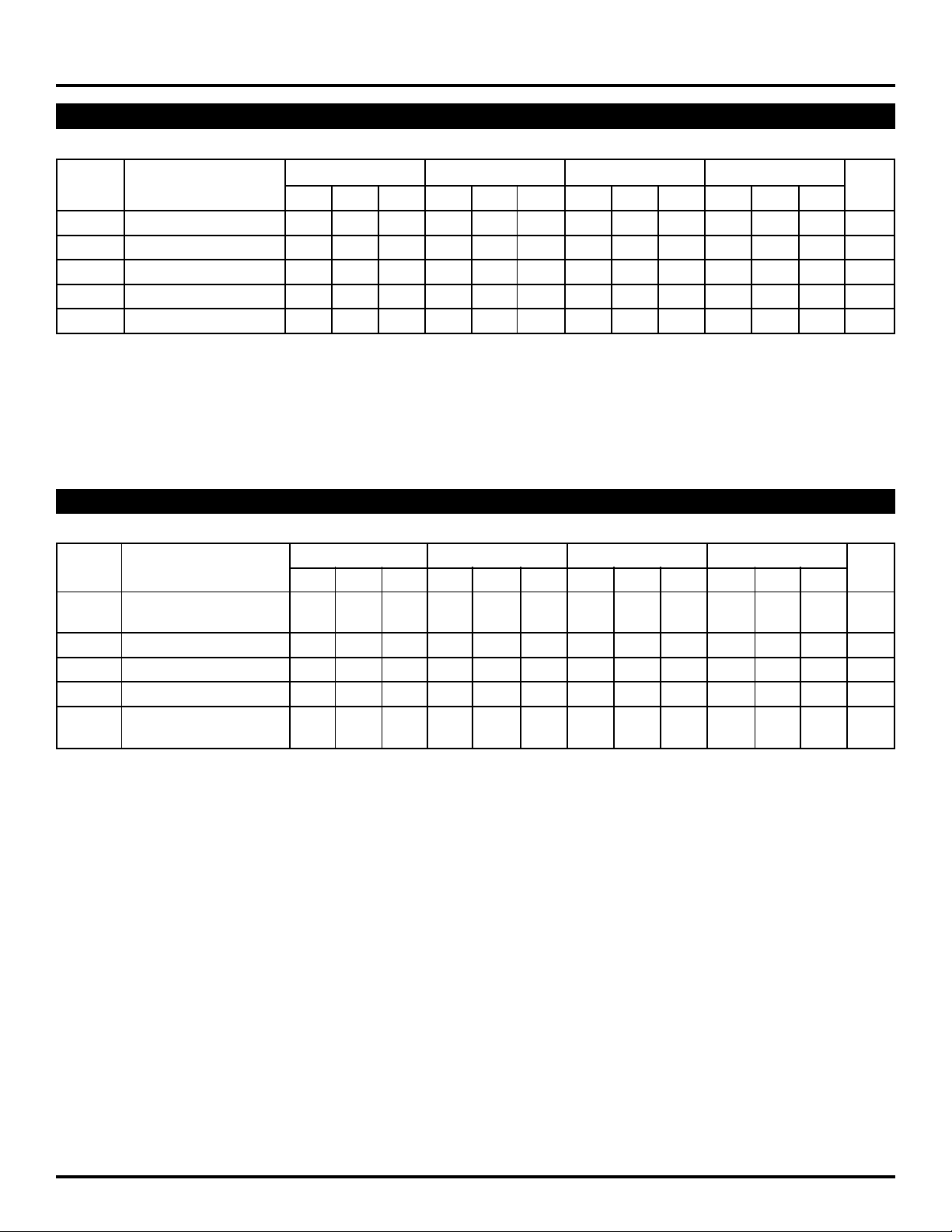
DC ELECTRICAL CHARACTERISTICS
VEE = VEE (Min.) to VEE (Max.); VCC = GND
TA = -40°CTA = 0°CTA = +25°CTA = +85˚C
Symbol Parameter Min. Typ. Max. Min. Typ. Max. Min. Typ. Max. Min. Typ. Max. Unit
IEE Power Supply Current 18 23 28 18 23 28 18 23 28 18 23 28 mA
VOH Output HIGH Voltage
VOL Output LOW Voltage
VEE Power Supply Voltage –4.75 —–5.5 –4.75 —–5.5 –4.75 —–5.5 –4.75 —–5.5 V
IH Input HIGH Current ——150 ——150 ——150 ——150 µA
I
NOTE:
OH and VOL specified for 50Ω to –3.0V load.
1. V
(1)
–1.23 –1.10 –0.98 –1.17 –1.05 –0.93 –1.13 –1.02 –0.90 –1.06 –0.96 –0.81 V
(1)
–2.84 –2.72 –2.58 –2.84 –2.70 –2.56 –2.84 –2.70 –2.56 –2.84 –2.67 –2.51 V
AC ELECTRICAL CHARACTERISTICS
VEE = VEE (Min.) to VEE (Max.); VCC = GND
TA = -40°CTA = 0°CTA = +25°CTA = +85˚C
Symbol Parameter Min. Typ. Max. Min. Typ. Max. Min. Typ. Max. Min. Typ. Max. Unit
PLH Propagation Delay to 200 340 480 250 340 430 260 350 440 310 400 490 ps
t
tPHL Output D
tskew Within-Device Skew — 520— 520— 520— 520ps
VPP Minimum Input Swing
VCMR Common Mode Range
r Output Rise/Fall Times Q 205 330 455 205 330 455 205 330 455 205 330 455 ps
t
tf (20% to 80%)
NOTES:
1. Minimum input swing for which AC parameters are guaranteed. The device has a DC gain of ≈40.
2. The CMR range is referenced to the most positive side of the differential input signal. Normal operation is obtained if the HIGH level falls within the specified
range and the peak-to-peak voltage lies between VPP min. and 1V. The lower end of the CMR range is dependent on VEE and is equal to VEE + 3.0V.
(1)
150 ——150 ——150 ——150 ——mV
(2)
(2) —–0.4 (2) —–0.4 (2) —–0.4 (2) —–0.4 V
2
Page 3
Micrel
DC BLOCKING CAPACITORS
DC BLOCKING CAPACITORS
75Ω
SY10EL89
75Ω COAX
EL89
0.1µF
150Ω 150Ω
V
EE
Figure 1. Termination Configuration
0.1µF
75Ω
75Ω
75Ω COAX
75Ω
PRODUCT ORDERING CODE
Ordering Package Operating
Code Type Range
SY10EL89ZC Z8-1 Commercial
SY10EL89ZCTR Z8-1 Commercial
3
Page 4
Micrel
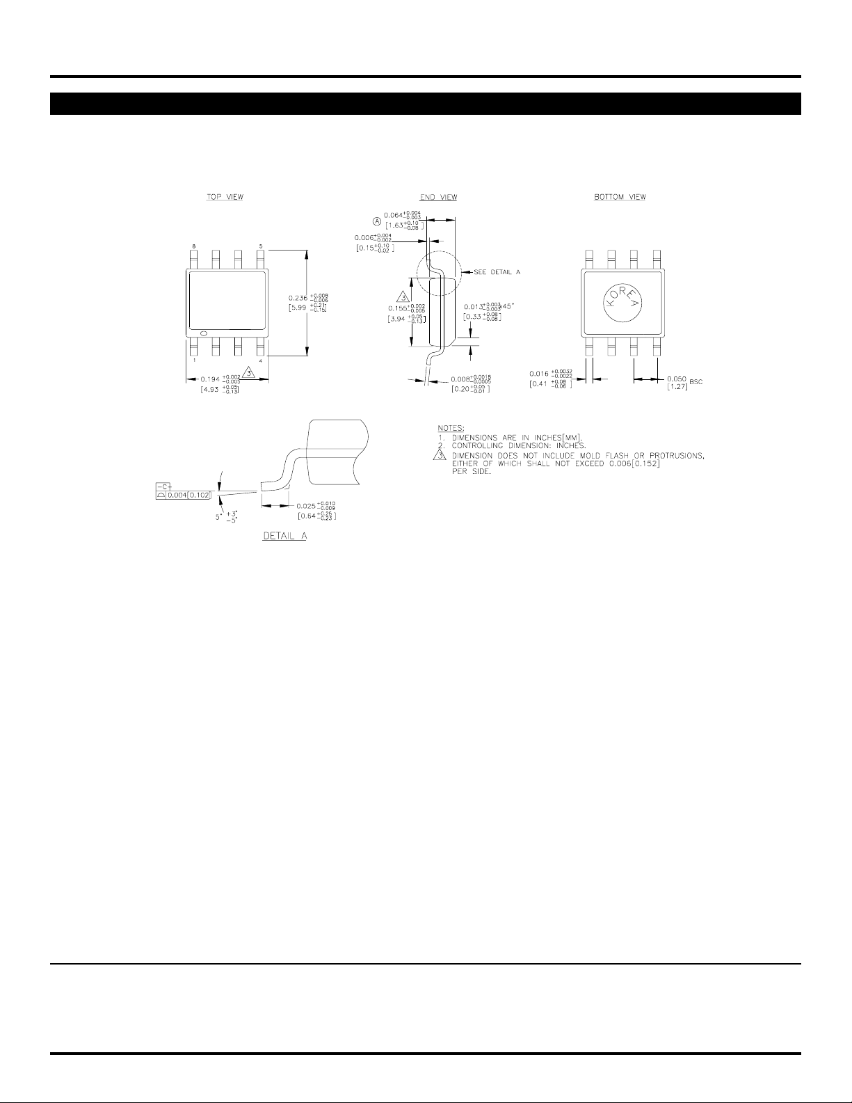
8 LEAD SOIC .150" WIDE (Z8-1)
SY10EL89
Rev. 03
MICREL-SYNERGY 3250 SCOTT BOULEVARD SANTA CLARA CA 95054 USA
TEL + 1 (408) 980-9191 FAX + 1 (408) 914-7878 WEB http://www.micrel.com
This information is believed to be accurate and reliable, however no responsibility is assumed by Micrel for its use nor for any infringement of patents or
other rights of third parties resulting from its use. No license is granted by implication or otherwise under any patent or patent right of Micrel Inc.
© 2000 Micrel Incorporated
4
 Loading...