

Page 1
16:1
MULTIPLEXER
SY10E164
SY100E164
FEATURES
■ 850ps Data Input to Output
■ Extended 100E V
EE range of –4.2V to –5.5V
■ Differential output
■ Fully compatible with industry standard 10KH,
100K ECL levels
■ Internal 75KΩ input pull-down resistors
■ Fully compatible with Motorola MC10E/100E164
■ Available in 28-pin PLCC package
BLOCK DIAGRAM
A
0
Q
Q
A
A
SEL
SEL
SEL
SEL
A
1
16:1
14
15
0
1
2
3
DESCRIPTION
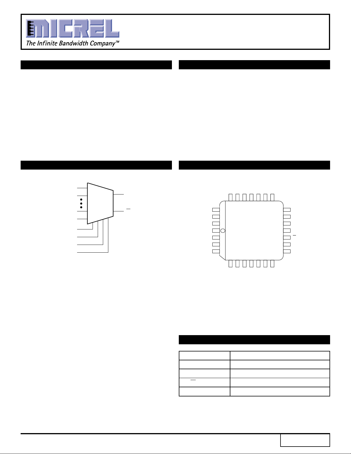
The SY10/100E164 are 16:1 multiplexers with a
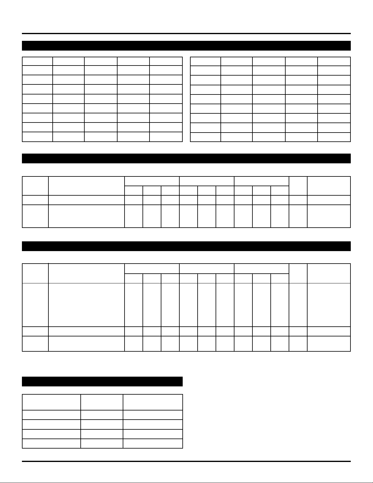
differential output. The select inputs (SEL0,1,2,3) control
which one of the sixteen data inputs (A0–A15) is
propagated to the output.
Special attention to the design layout results in a typical
skew between the 16 inputs of only 50ps.
PIN CONFIGURATION
15
14
12
11
SEL
V
SEL
SEL
SEL
A
A
EE
10
A
24 23 22 21 20 19
25
26
9
27
8
3
28
1
2
2
0
3
1
4
567891011
13
A
A
A
PLCC
TOP VIEW
J28-1
CCO
A
A
V
18
NC
17
NC
16
V
CC
15
Q
14
Q
13
12
V
A
CCO
0
7
A6A
3
4
5
A
A
A
PIN NAMES
Pin Function
A0 – A15 Data Inputs
SEL[0:3] Select Inputs
Q, Q Outputs
V
CCO VCC to Output
1
2
A
A
Rev.: D Amendment: /0
1
Issue Date: July, 1999
Page 2
Micrel
TRUTH TABLE
SY10E164
SY100E164
SEL3 SEL2 SEL1 SEL0 Data
LLLLA0
LLLHA1
LLHLA2
LLHHA3
LHLLA4
LHLHA5
LHHLA6
LHHHA7
SEL3 SEL2 SEL1 SEL0 Data
HLLLA8
HLLHA9
HLHLA10
HLHHA11
HHLLA12
HHLHA13
HHHLA14
HHHHA15
DC ELECTRICAL CHARACTERISTICS
VEE = VEE (Min.) to VEE (Max.); VCC = VCCO = GND
TA = 0°CTA = +25°CTA = +85°C
Symbol Parameter Min. Typ. Max. Min. Typ. Max. Min. Typ. Max. Unit Condition
IIH Input HIGH Current ——150 ——150 ——150 µA —
I
EE Power Supply Current mA —
10E — 59 71 — 59 71 — 59 71
100E — 59 71 — 59 71 — 68 81
AC ELECTRICAL CHARACTERISTICS
VEE = VEE (Min.) to VEE (Max.); VCC = VCCO = GND
TA = 0°CTA = +25°CTA = +85°C
Symbol Parameter Min. Typ. Max. Min. Typ. Max. Min. Typ. Max. Unit Condition
t
PLH Propagation Delay to Output ps —
tPHL A Input 350 600 850 350 600 850 350 600 850
SEL0 500 700 900 500 700 900 500 700 900
SEL1 400 675 900 400 675 900 400 675 900
SEL2 400 675 900 400 675 900 400 675 900
SEL3 400 550 700 400 550 700 400 550 700
tskew Within-Device Skew — 50 ——50 ——50 — ps 1
r Rise/Fall Times 275 400 550 275 400 550 275 400 550 ps —
t
tf 20–80%
NOTE:
1. Within-device skew is defined as the difference in the A to Q delay between the 16 different A inputs.
PRODUCT ORDERING CODE
Ordering Package Operating
Code Type Range
SY10E164JC J28-1 Commercial
SY10E164JCTR J28-1 Commercial
SY100E164JC J28-1 Commercial
SY100E164JCTR J28-1 Commercial
2
Page 3
Micrel
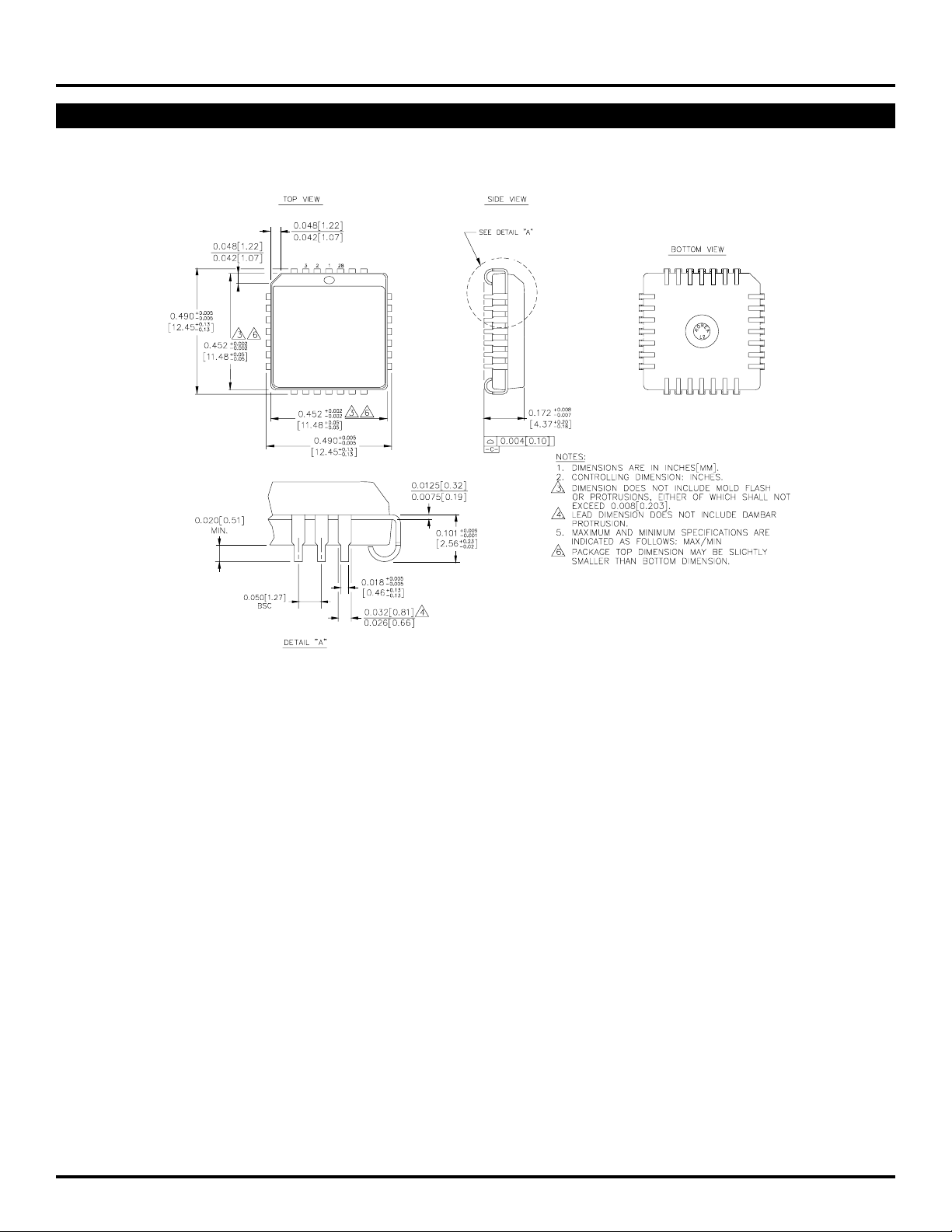
28 LEAD PLCC (J28-1)
SY10E164
SY100E164
Rev. 03
3
Page 4

Micrel
SY10E164
SY100E164
MICREL-SYNERGY 3250 SCOTT BOULEVARD SANTA CLARA CA 95054 USA
TEL + 1 (408) 980-9191 FAX + 1 (408) 914-7878 WEB http://www.micrel.com
This information is believed to be accurate and reliable, however no responsibility is assumed by Micrel for its use nor for any infringement of patents or
other rights of third parties resulting from its use. No license is granted by implication or otherwise under any patent or patent right of Micrel Inc.
© 2000 Micrel Incorporated
4
 Loading...