

Page 1
SVC347
Ordering number : EN5816
Varactor Diode (IOCAP) for
AM Receiver Electronic Tuning
Silicon Diffused Junction Type
SANYO Electric Co.,Ltd. Semiconductor Bussiness Headquarters
TOKYO OFFICE Tokyo Bldg., 1-10, 1 Chome, Ueno, Taito-ku, TOKYO, 110 JAPAN
O1497GI (KOTO) No.5816-1/3
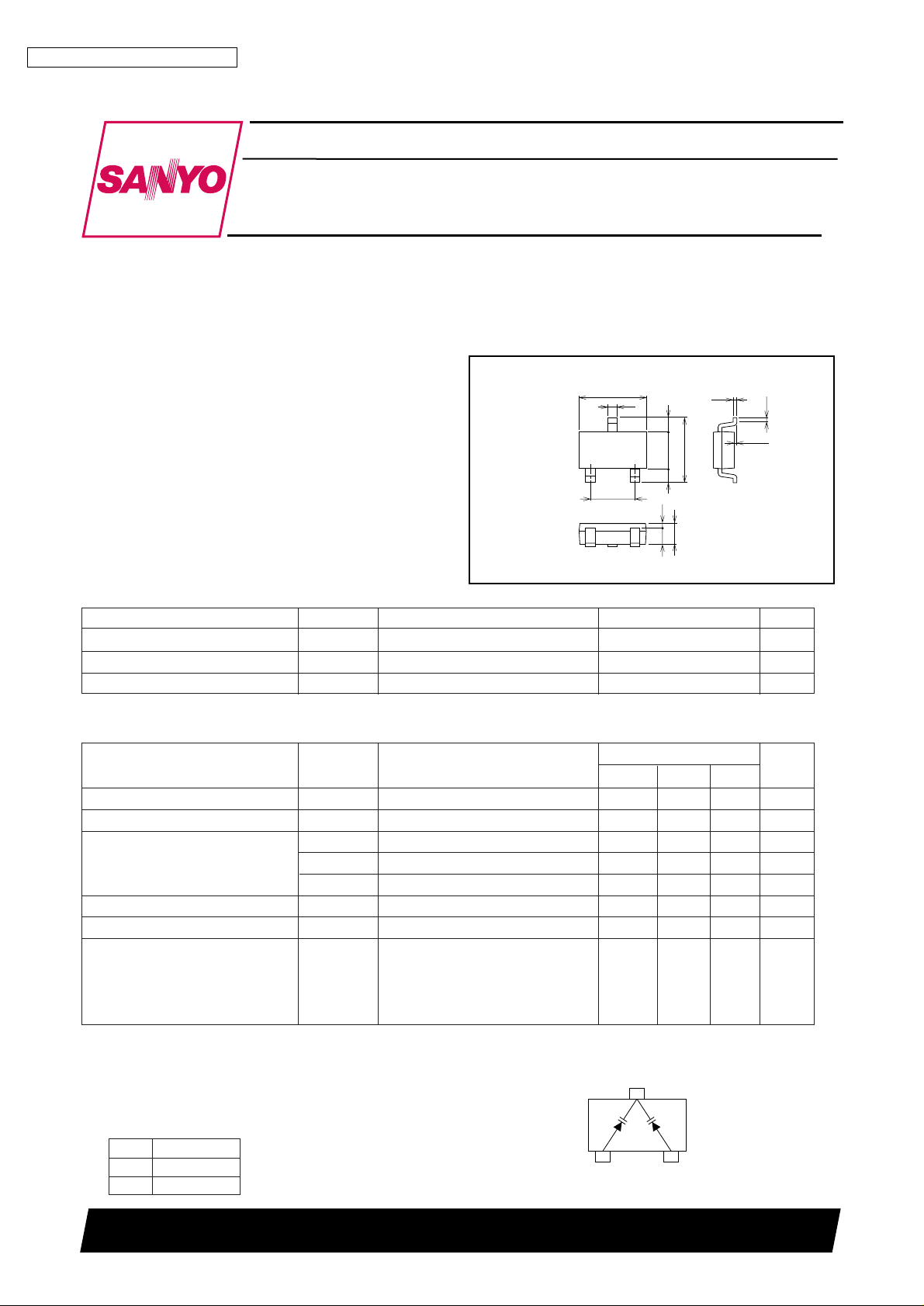
Package Dimensions
unit: mm
1291
[SVC347]
SANYO: CPH3
1 : Anode
2 : Anode
3 : Cathode
0‘0.1
0.9
0.7 0.2
1.6 0.60.6
1.9
12
3
2.8
0.2
2.9
0.15
0.4
Specifications
Absolute Maximum Ratings
at Ta=25°C
Parameter Symbol Conditions Ratings Unit
Reverse voltege V
R
16 V
Junction temperature Tj 125 °C
Storage temperature Tstg –55 to +125 °C
Electrical Characteristics at Ta=25°C
Parameter Symbol Conditions
Ratings
min typ max
Unit
Breakdown voltage V
(BR)R
IR=10µA 16 V
Reverse current (One diode) I
R
VR=9V 100 nA
Interterminal capacitance C
1V
VR=1V, f=1MHz *1 470
*
535
*
pF
(Capacitance value of C
6V
VR=6V, f=1MHz 55 pF
one diode) C
8V
VR=8V, f=1MHz 20 26 pF
Quality factor Q VR=1V, f=1MHz 200
Capacitance ratio CR C1V/ C8V, f=1MHz 18.5
Matching tolerance *2 ∆Cm (Cmax – Cmin) / Cmin
×100
VR=1V, f=1MHz 2.5 %
VR=6V, f=1MHz 3.0 %
VR=8V, f=1MHz 3.0 %
*1 : 1MHz signal : 20mVrms
Electrical Connection
*2 : Matching tolerance between D1 and D2
*
: The SVC347 is classified bosed on C1V capacitance
as shown in the table below :
Features
• Twin type varactor diode for AM electronic tuning use.
• Miniaturization and high-integration of tuner sets can be
easily achieved due to the small package.
• High capacitance ratio and high quality factor.
• Provided in a tape reel packaging.
• Surface mount type.
A09978
1:Anode
2:Anode
3:Cathode
12
D2D1
3
(top view)
Rank C1V (pF)
S 470 to 505
T 495 to 535
Page 2
SVC347
No.5816-2/3
–50 –25 0 25 50 75 100 125
0.94
0.96
0.98
VR=8V
3V
1V
6V
7V
5V
VR=5V
1V
6V
7V
3V
8V
1.00
1.02
1.06
1.08
1.04
Ta — ˚C
Capacitance ratio
C — Ta
f=1MHz
Vrf=20mVrms
0 1 2 3 4 5 6 7 8 9 10
10
20
30
50
70
100
200
300
500
700
1000
Reverse voltage, VR – V
Interterminal capacitance, C – pF
Interterminal capacitance, C L-axis
100
200
300
500
700
1000
2000
3000
5000
7000
10000
Quality factor, Q
Quality factor, Q R-axis
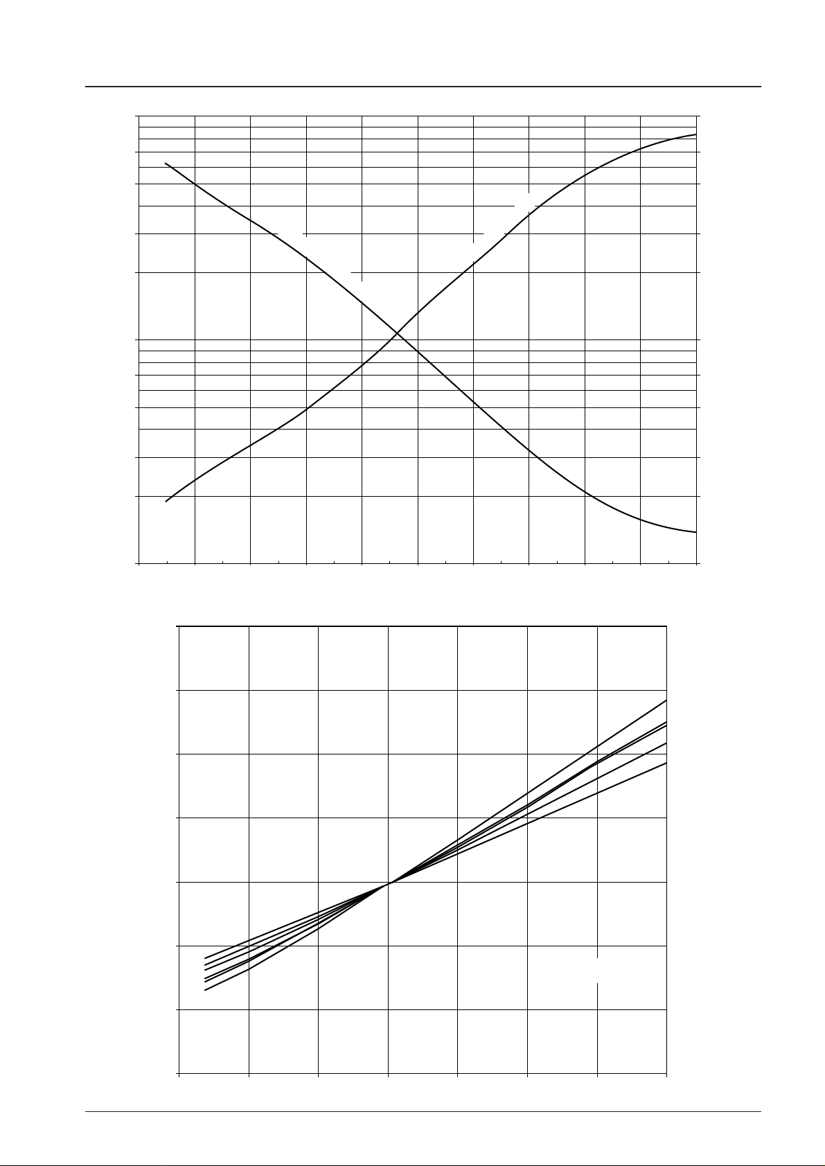
C,Q — VR (at f=1MHz Vrf=20mVrms)
Page 3

SVC347
No.5816-3/3
No products described or contained herein are intended for use in surgical implants, life-support systems,
aerospace equipment, nuclear power control systems, vehicles, disaster/crime-prevention equipment and
the like, the failure of which may directly or indirectly cause injury, death or property loss.
Anyone purchasing any products described or contained herein for an above-mentioned use shall:
Accept full responsibility and indemnify and defend SANYO ELECTRIC CO., LTD., its affiliates,
subsidiaries and distributors and all their officers and employees, jointly and severally, against any
and all claims and litigation and all damages, cost and expenses associated with such use:
Not impose any responsibilty for any fault or negligence which may be cited in any such claim or
litigation on SANYO ELECTRIC CO., LTD., its affiliates, subsidiaries and distributors or any of
their officers and employees jointly or severally.
Information (including circuit diagrams and circuit parameters) herein is for example only; it is not guaranteed for volume production. SANYO believes information herein is accurate and reliable, but no guarantees
are made or implied regarding its use or any infringements of intellectual property rights or other rights of
third parties.
This catalog provides information as of October, 1997. Specifications and information herein are subject
to change without notice.
 Loading...