

Page 1

SPX-5631
2.4 GHz
EXP-2000
Suprex
®
RF
SPX-5631 & SPX-5641
Wireless Reader-Extender
Product Manual
SPX-5631_SPX-5641_MAN_181129
Cypress Integration Solutions 35 Years of Access Control Ingenuity CypressIntegration.com
© 2018 Cypress Computer Systems 1778 Imlay City Road, Lapeer, MI 48446 800-807-2977
Page 2

2
Specifications
Part Numbers
SPX-5631
816684008115
Short-range wireless reader extender
SPX-5641
816684001352
Long-range wireless reader extender
RPT-5651
816684003172
Optional wireless repeater
EXP-2000
816684003233
Optional expansion modules to connect additional readers
Physical
SPX-5631 / SPX-5641 Enclosure
9.25” x 7.0” x 2.25” / 1.3 lbs (diagram below)
EXP-2000 Enclosure
4.5” x 2.9” x 0.94” / 0.3 lbs (diagram below)
Environmental
Storage Temperature
-40˚C to 100˚C
Operating Temperature
-30˚C to 60˚C
Enclosure Rating
Weatherproof Enclosure - ABS - IP65
Electrical
Central and Remote Supply Voltage
8-16Vdc Current 300mA
Relays
Max Switching
220Vdc 30W (resistive) 1A / 250Vac 37.5VA 1A
Running Spec with load
30Vdc 1A (resistive) / 125 Vac 0.3A (resistive), 1x10⁵ operations @ 20˚C
Radio
Frequency
2.4 GHz ISM band
Type
Direct Sequence Spread Spectrum (DSSS)
Transmit Power
15 dBm
Receiver Sensitivity
-103 dBm (1% PER, 250Kbps)
Modulation
O-QPSK
Agency Approvals
FCC Part 15.247: FCC ID: U90-SM220
Industry Canada (IC): 7084A-SM220
CE Certified: Certified to EN300 328 Version 1.8.1
Security Encryption
AES encryption upon request (export restrictions may apply)
Wireless
range
SPX-5631
Maximum of 2000 feet*
SPX-5641
Maximum of 10000 feet*
RPT-5651
Maximum of 2000 feet*
*Note: Distances are typical line-of-sight. Actual distance may vary depending upon terrain, RF environment, building
materials, and height of antenna.
Additional
Features
SPX-5631 and SPX-5641 include complete solution with Central (controller) and Remote (reader/gate/door) interface
“Quiet” bandwidth and power
Field configurable wireless channel, network ID, and pairing
On board relays to control door/gate
Auxiliary I/O available for LED signal and door/gate/panel status signal
Status LED and Supervision Relay (default off) monitor wireless connection status
The Suprex® RF SPX-5631 and SPX-5641 series makes it possible to install card readers far from the access control
panel, by providing a point-to-point wireless link between most manufacturers’ controllers and the door or gate readers.
The Suprex® includes both a Remote (door/gate) unit and a Central (Access Controller) unit. Optional repeaters and
extenders are also available. The SPX-5631 & SPX-5641 series devices are compatible with the RPT-5661 repeater,
and with the EXP-2000 expansion modules.
Cypress Suprex® RF Series - SPX-5631 & SPX-5641 Overview
Page 3

3
Table of Contents
Topic
Page
Overview and Specifications
2
Physical Dimensions and Mounting Hole Locations
4
Central and Remote Pin Layout
5
Setup and Pre-Installation
6
Indicators and Operating Modes
7
Common Configuration and Run Mode Settings
8
DIP Switch Map
9
Using Remote Digital Relay Inputs
10
Quick Reference for Typical Connections
11
Repeater Installation
12
Troubleshooting
13
Accessory I/O
I/O Overview
14
Central Relay Inputs
15
Relay 1 & 2 I/O
16
Remote Relay Inputs
17
Relay 3 & 4 I/O
18
LED I/O
19
Aux I/O
20
Application Note on Using Supervised Contacts
21
EXP-2000
Expansion Modules
Overview and Operation
22
Central EXP Wiring Diagram
23
Remote EXP Wiring Diagram
24
Radio Configuration
25
Radio Configuration (continued)
26
Page 4

4
Cypress Suprex® RF Series - Physical Dimensions and Mounting Hole Locations
All dimensions are listed in inches.
EXP Enclosure
ø 0.120 X 4
4.125"
2.890"
3.155"
2.121"
2.364"
EXP-2000
ø 0.120 X 4
3.065"
2.770"
4.0625"
2.660"
2.940"
SPX-5631 /
SPX-5641 /
RPT-5651
9.25"
7.0"
Thickness:
2.25"
Page 5

5
8-16VDC Input
Ground
EXP (+)
EXP (-)
+5VDC Output
Prog Res 2
Prog Res 1
LED Input
D1 / Data Out
D0 / Clock Out
Relay 4 N.O.
Relay 4 COM
Relay 4 N.C.
Relay 3 N.O.
Relay 3 COM
Relay 3 N.C.
Ground
Aux Output
Relay 2 Input
Relay 1 Input
Relay 2 N.O.
Relay 2 COM
Relay 2 N.C.
Relay 1 N.O.
Relay 1 COM
Relay 1 N.C.
Ground
Aux Input
Not Used
Not Used
8-16 VDC Input
Ground
EXP (+)
EXP (-)
+5VDC Output
Relay 4 Input
Relay 3 Input
LED Output
D1 / Data Input
D0 / Clock Input
SPX-5631 / SPX-5641 Central Unit
SPX-5631 / SPX-5641 Remote Unit
Cypress Suprex® RF Series - Central and Remote Pin Layout
Page 6

6
Dipole antenna example
Chip antenna example
Cypress Suprex® RF Series - Setup and Pre-installation
Antenna orientation and field placement:
See examples below for Suprex® RF units with dipole antennas and “chip” antennas.The orientation of the dipole
antenna is critical for performance. The antenna should always be oriented vertically. Orientation of Suprex® RF units
with an internal “chip” antenna is not as critical.
Radio frequencies in the 2.4 GHz bands have characteristics that require a direct line of sight (LOS) between the
transmitter and receiver. For best performance the antennas of the Central and Remote should “see” each other without
obstructions.
There are limited exceptions in which the signal will still pass between the transmitter and receiver without line of sight
placement. In some cases, the communication path will work but at a reduced distance.
For outdoor installations: When possible, place the units on the exterior of buildings to reduce interference. Repeaters/
Boosters are available if needed.
Final Field Installation Checklist:
•
The Central unit and access control panel should have a common ground.
•
The Remote unit and card reader should have a common ground.
•
The top of each unit (where antennas are located) should point up toward the sky.
•
The Central and Remote units should be installed level relative to each other.
•
There should be a direct line of sight between Central and Remote units (if there is no direct line of sight, a
Repeater unit is recommended).
•
Both the Central and Remote units should be mounted high enough to avoid interference from obstacles
(vehicles, trains, buildings, trees, etc.).
•
Metal mounting surfaces are not recommended. If use of a metal surface is unavoidable, space unit as far from
metal surface as possible using non-metal spacer.
Unpacking:
Remove covers from units and check interior for any shipping damage. Remove any packing material if present.
Inventory any included parts (depending on model) such as antennas, coaxial cables etc.
Bench Testing:
Before installing the units in the field they should be assembled and tested at a convenient benchtop location. This will
make it easier to verify / change settings and check operation when both units are visible.
This is also an opportunity to become familiar with the system if this is the first use of the Suprex system. It is much more
difficult to set up and test the units when they are several thousand feet apart.
Both units will need to have the antenna and a suitable power supply connected. For testing purposes, the units can
share the same power supply.
Basic Bench Test:
During initial setup, refer to the Run / Configuration mode settings (pgs 7-9).
1.
Connect a suitable power supply to both units. Each unit should be provided with 8 - 16 Volts dc and approx 300mA.
Units should be separated by a minimum of 24 inches.
2.
Apply power. After about a 1-2 second delay, the Diagnostic LED on both units should flash green. The supervision
relay (Relay 3) activates when the units are communicating. Note: Supervision relay is disabled by default (see pgs. 7-9).
3.
Touch a jumper wire from the Ground connection to the Relay 1 input on the Central unit. Relay 1 on the Remote unit
should activate with an audible click.
4.
Units are shipped from the factory set for the Wiegand data format. If a different format is required, set the DIP switch to
the required reader and panel format (see pgs. 7-9)
5.
If a reader & panel are accessible, connect the reader to the Remote unit & the Central unit to the panel to verify card
reads are accepted by the access control system. If troubleshooting is necessary, it is easier with units in close proximity.
6.
Once these steps are completed, the units are ready for installation at their permanent locations.
Page 7

7
LED DIAGNOSTIC INDICATOR
The LED Diagnostic indicator provides information on the operational status of the unit.
If the units are not communicating, viewing the diagnostic indicator LEDs may help to determine the
nature of the problem. See also Troubleshooting, page 13.
•
If Central or Remote diagnostic LED is not illuminated:
If the LED(s) are not illuminated on the unit(s), the unit is not powered or there is an electrical problem.
When power is properly applied, the Diagnostic LEDs will be illuminated to show a status below:
•
If the Central and Remote unit LEDs are flashing green:
When power is properly applied, and there is communication between the Central and the Remote, the
Central and Remote unit LEDs will flash green after every polling cycle. The speed will depend on how
many expansion units are connected (about 1 flash per second with 7 EXPs).
•
If the Central or Remote unit LED alternates between green/red:
There is no communication with the partner unit.
•
If the Central or Remote unit LEDs are solid green:
If the unit is in Configuration Mode, the settings have been successfully applied, it is safe to power
cycle the unit and switch back to Run Mode. If the unit is in Run Mode, one of the EXPs is not
communicating properly. Check that all connected EXPs are powered and properly connected. (For
details on setting Configuration Mode, see pgs. 7-9.)
OPERATING MODES
Wireless Suprex products have 3 operating modes: Run Mode, Configuration Mode, and Test Mode.
•
Run Mode: The units are factory-shipped in Run Mode. Run Mode is used during field operation of units.
Run Mode allows changing of common settings without the need to power-cycle the units. Factory-set
defaults can be changed. Default settings:
•
Units are set to operate as 1 Remote and 1 Central unit
•
Supervision relay is disabled
•
Pullup resistors are disabled
•
Number of EXP Expansion Modules is set to 0
•
Configuration Mode: Switch to Configuration Mode to change the link type and interface type. Default
settings:
•
Default interface type is Wiegand
•
Link type is pre-set based on the Suprex model
•
Test Mode: Test Mode is used for troubleshooting the reader/panel connection to the Remote/Central
unit. In Test Mode, DIP Switches 3-8 operate as if in Run Mode. Either a single unit or both units can be
set to Test Mode; the Remote and Central units retain all their normal functionality in addition to the
following functions:
•
In Test Mode, the Central unit outputs a test card read in the selected interface type every few
seconds
•
In Test Mode, the Remote unit briefly triggers Relay 2 when detecting data of the selected interface
type
Cypress Suprex® RF Series - Indicators and Operating Modes
Page 8

8
Test Mode Select
Turn DIP switch 2 on for Remote &/or Central
Default: Standard Wiegand
Turn on DIP switch 8 on both units
Keypad (Wiegand/No Filter)
Turn on DIP switch 7 on both units
F/2F (Unsupervised)
Turn on DIP switches 6, 7, 8 on both units
Strobed Rising Edge (MR-5)
Turn on DIP switches 7 and 8 on both units
Strobed Rising Edge (Dorado 644)
Turn on DIP switch 6 on both units
Strobed Rising (MagTek)
Turn on DIP switches 6 and 8 on both units
Strobed Falling Edge
Turn on DIP switches 6 and 7 on both units
Configuration Mode settings
Standard Wiegand interface is the default setting. To use with non-Wiegand interface:
a) Power off both Suprex units.
b) Turn on DIP switch 1 on both units.
c) Set DIP switches as described below for appropriate interface:
d) Power on both Suprex units. Status LED should be solid green.
e) Power off both Suprex units; return DIP switch 1 to off position on both units to select Run
Mode settings. When switching to Run Mode, always reselect Run Mode settings.
Central / Remote Select
Turn DIP switch 3 on for Central Mode /
turn off for Remote Mode
Remote Digital/Analog Relay Select
Turn Remote Unit's DIP switch 2 on for digital
input / off for analog input
Supervision Relay (Relay 3, Central Unit)
Turn Central Unit's DIP switch 4 on for supervision
relay / off for normal relay
Supervision Relay (Relay 1, Remote Unit)
Turn Remote Unit's DIP switch 4 on for supervision
relay / off for normal relay
Pullup Resistor Select
Turn on DIP switch 5 to enable pullup resistors / off
to disable [applicable units)
EXP Select (for no EXP)
Turn off DIP switches, 6, 7, and 8 on both units
EXP Select (for 1 EXP)
Turn on DIP switch 8 on both units
EXP Select (for 2 EXPs)
Turn on DIP switch 7 on both units
EXP Select (for 3-7 EXPs)
See pg. 9
Run Mode settings
Select Run Mode settings as described below, then power on both Suprex units to begin operating
in Run Mode.
Cypress Suprex® RF Series - Common Configuration and Run Mode Settings
Test Mode setting
See page 13 to troubleshoot using Test Mode.
Page 9
9
Run Mode
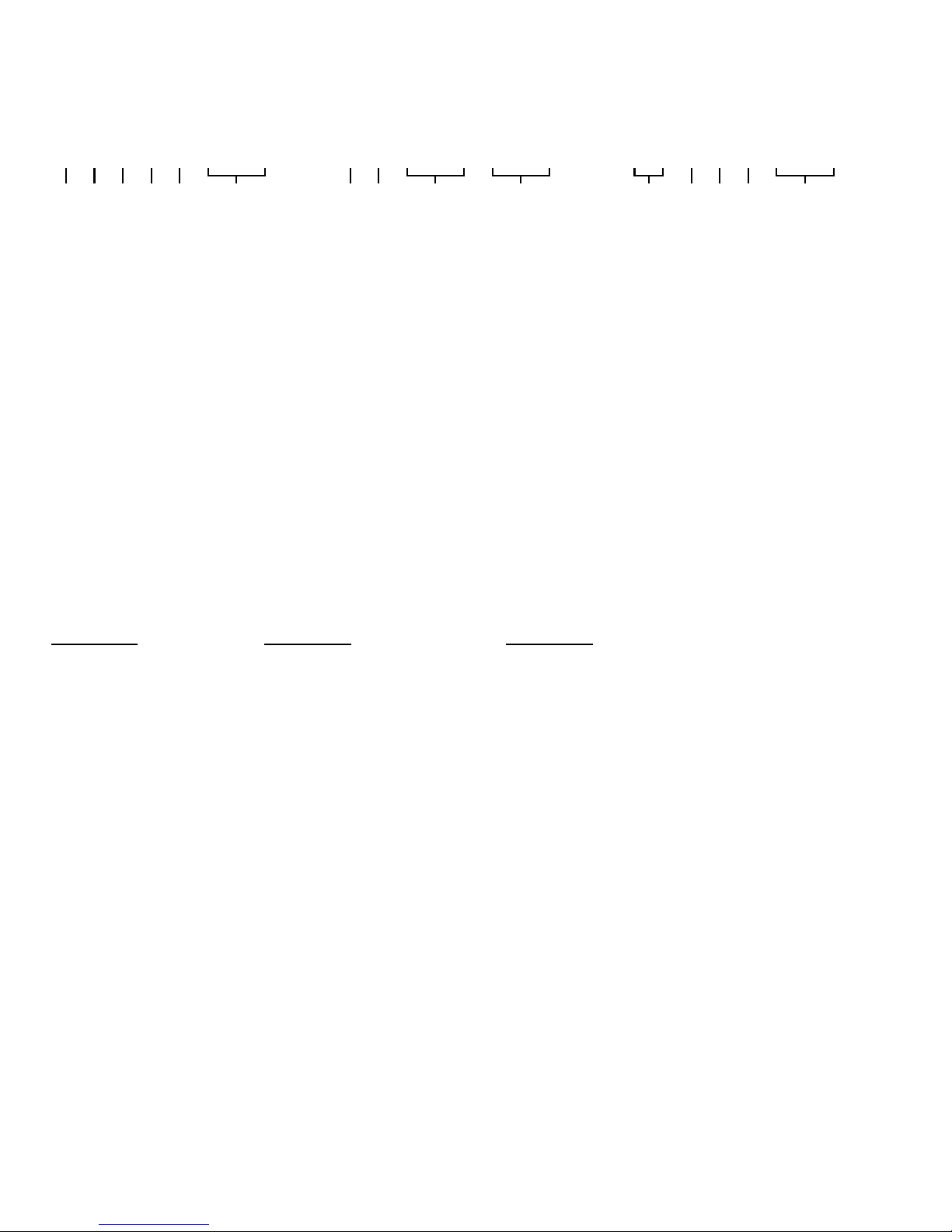
1 2 3 4 5 6 7 8
Configuration Mode Select
Remote Relay Mode Select
Central / Remote Select
Supervision Relay Select
Pullup Resistor Select
# of EXP-2000s
Configuration Mode
1 2 3 4 5 6 7 8
Configuration Mode Select
Not Used
Link Type Select
Interface Type Select
Supervision Relay SelectSupervision Relay Select
Test Mode
1 2 3 4 5 6 7 8
Test Mode Select
Central / Remote Select
Supervision Relay Select
Pullup Resistor Select
Interface Type Select
NOTE - 0 = OFF - 1 = ON
Configuration Mode Select - ON = Configuration Mode - OFF = Run Mode
Remote Relay Mode Select - ON = Digital Input - OFF = Analog Input
Central / Remote Select - ON = Central - OFF = Remote
Supervision Relay Select - ON = Enable Supervision Relay - OFF = Disable Supervision Relay
Pullup Resistor Select - ON = Enable Pullup Resistor - OFF = Disable Pullup Resistor
Test Mode Select - DIP Switches 1 & 2 ON = Test Mode
- The DIP Switch selections in Run Mode and Test Mode are ACTIVE, meaning that they can be changed on
the fly without power cycling the unit.
- The DIP Switch selections in Configuration Mode are NOT ACTIVE. This means to set Configuration Mode
setting the unit will need to be powered off, turn DIP 1 on and other Configuration DIP Switches as needed,
power the unit on and the Status LED will be solid green. The solid green LED means the settings have been
set. Power the unit off and return the DIP Switches to the Run Mode positions.
- When using the Remote unit with digital relay inputs the relays are controlled by the "not used" pins on the 10
pin header. Connect the outside "not used" pin to "Ground" to trigger Relay 3. Connect the inside "not used" pin
to "Ground" to trigger Relay 4.
- When using the Remote unit with analog relay inputs the relays are controlled by the "Relay 3 in" and "Relay 4
in" pins. Connect "Relay 3 in" to "Ground" to trigger Relay 3. Connect "Relay 4 in" to "Ground" to trigger Relay4.
# of EXP-2000 Pairs
0 0 0 - None
0 0 1 - 1 Pair
0 1 0 - 2 Pairs
0 1 1 - 3 Pairs
1 0 0 - 4 Pairs
1 0 1 - 5 Pairs
1 1 0 - 6 Pairs
1 1 1 - 7 Pairs
6 7 8 - (Run Mode)
Link Type Select
0
0 0 - No Change
0 0 1 - Wireless
3 4 5
- (Config Mode)
Interface Type Select
0 0 0 - No Change
0 0 1 - Wiegand
0 1 0 - Wiegand No Filter
0 1 1 - Strobed Rising (MR5)
1 0 0 - Strobed Rising (Dorado 644)
1 0 1 - Strobed Rising (Mag-Tek)
1 1 0 - Strobed Falling
1 1 1 - Unsupervised F/2F
6 7 8 - (Config and Test Mode)
-The Remote Relay Mode Select (Dip Switch 2 in Run Mode) is only used on the Central unit, and has no
functionality on the Remote unit.
Cypress Suprex® RF Series - SPX-5631 / SPX-5641 DIP Switch Map
Page 10
10
Cypress Suprex® RF Series - Using the Remote Digital Relay Inputs
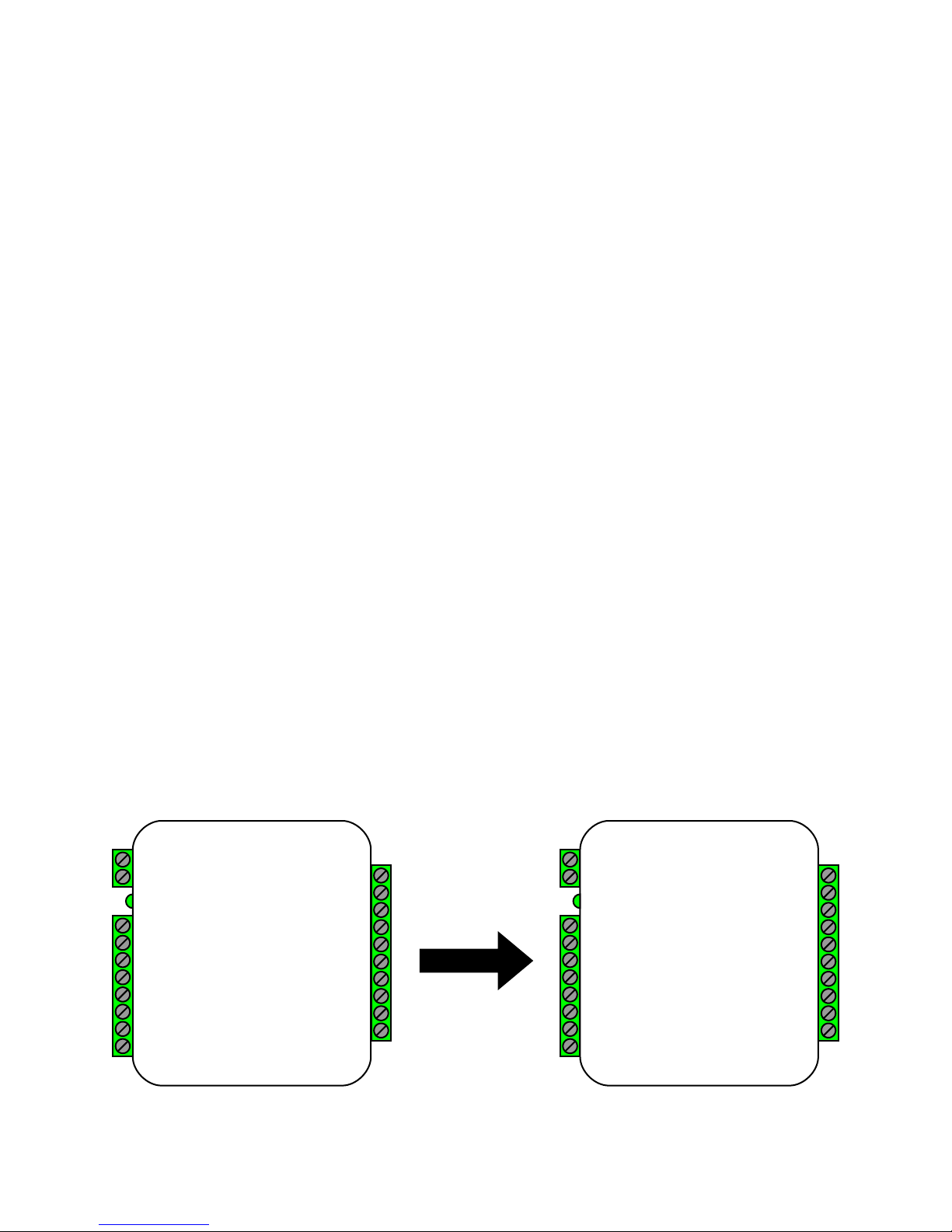
This section applies only to the Remote unit, as the Central unit has only digital relay inputs. DIP
switch 2 controls whether the Remote unit uses the analog relay inputs or the digital relay inputs. By
default, DIP switch 2 is off and the Remote unit is set to use the analog relay inputs. When DIP switch
2 is in the ON position, the Remote unit is set to use the digital relay inputs. The digital relay inputs
function in the same way the analog inputs on the Remote unit function. The digital relay inputs simply
need to be connected to ground for the corresponding relay to be activated.
To active the digital relay inputs, only DIP switch 2 on the Central board needs to be enabled. DIP
switch 2 on the Remote board has no function. It may be necessary to power-cycle the Central unit for
the change to take effect.
Note: The digital relay input pins are not the same Relay 3 and Relay 4 input pins labeled on the
Remote unit. Instead, the digital relay input pins use the two “Not Used” pins on the 10 pin header. The
“Not Used” pin on the outside of the board is the new Relay 3 input pin, the other “Not Used” pin is the
new Relay 4 input pin. Use the diagram below as a reference.
For most applications the analog relay inputs are sufficient. But for instances where a significant delay
is noticed in the activation of Relay 3 and Relay 4, the end user should switch to using digital relay
inputs. The digital relay input pins are able to detect a signal change faster than the analog inputs are,
and this may eliminate the delay in the activation of the relay.
Note regarding EXP units: While DIP switch 2 is on and the digital relay input pins are enabled on
the SPX-5631 / SPX-5641 units, the digital relay inputs are also enabled on any EXP-2000 Remote
units that are connected. The digital relay input pins are on the 12 pin header and are the two “Not
Used” pins. The outside “Not Used” pin is the Relay 3 Input pin and the other “Not Used” pin is the
Relay 4 Input pin.
+8 to +16 VDC
Ground
exp(+)
exp(-)
+5V Out
Relay 4 Input
Relay 3 Input
LED Out
D1/Data In
D0/Clock In
Relay 2 N.O.
Relay 2 Com
Relay 2 N.C.
Relay 1 N.O.
Relay 1 Com
Relay 1 N.C.
Ground
Aux Input
Not Used
Not Used
+8 to +16 VDC
Ground
exp(+)
exp(-)
+5V Out
Not Used
Not Used
LED Out
D1/Data In
D0/Clock In
Relay 2 N.O.
Relay 2 Com
Relay 2 N.C.
Relay 1 N.O.
Relay 1 Com
Relay 1 N.C.
Ground
Aux Input
Relay 4 Input
Relay 3 Input
DIP Switch 2 Off
(Analog Inputs)
DIP Switch 2 On
(Digital Inputs)
Analog and Digital Relay Input Pins
Remote
Remote
Page 11
11
Cypress Suprex® RF Series - Quick Reference For Typical Connections
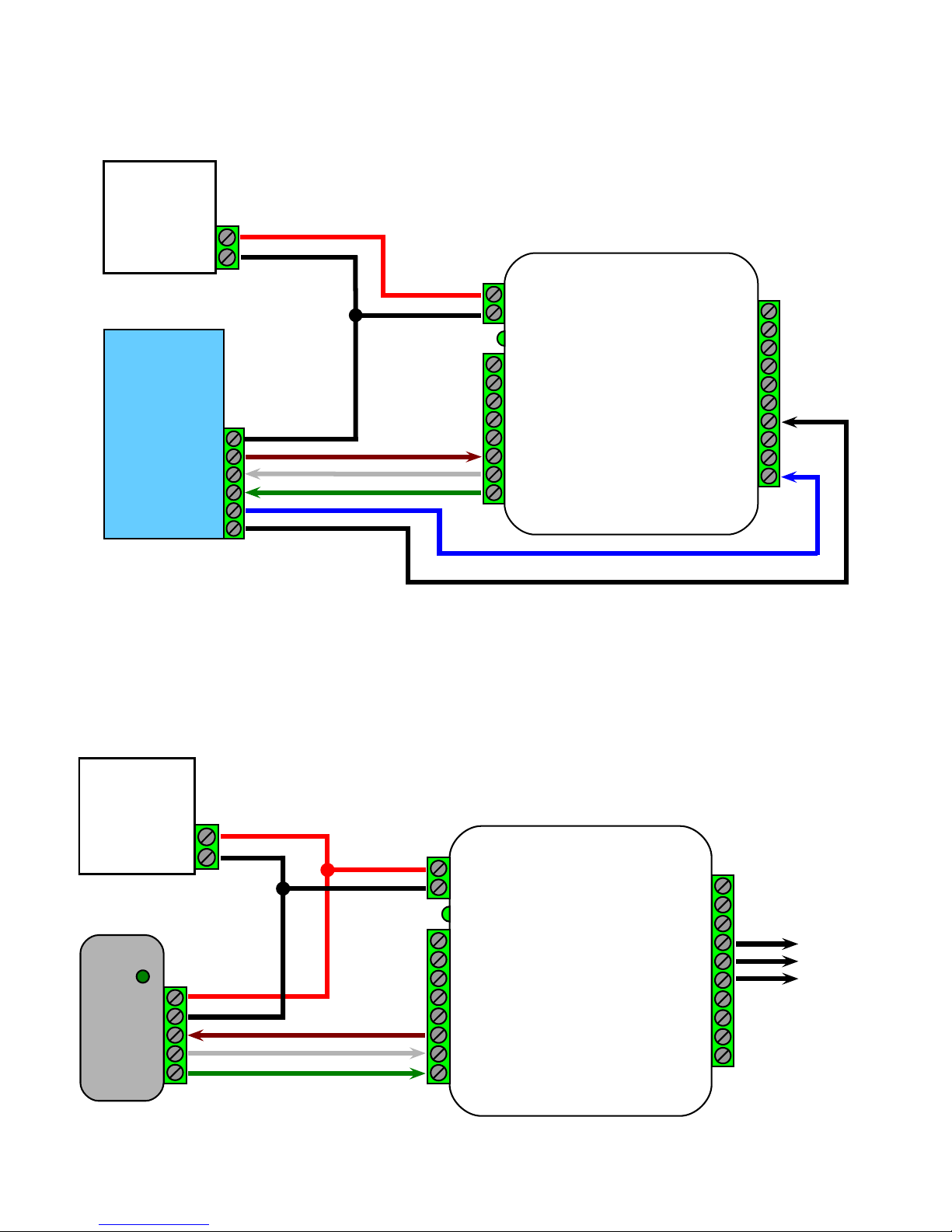
In this wiring example, the door strike follows a dry contact input from the access control panel. See page 15 for
other strike control options.
Ground
LED Out
Data1
Data 0
N.O.
COM
Access
Control
Panel
DC Power
Supply
Power
Ground
+8 to +16 VDC
Ground
exp(+)
exp(-)
+5V Out
P R 4
P R 3
LED In
D1/Data Out
D0/Clock Out
Relay 4 N.O.
Relay 4 Com
Relay 4 N.C.
Relay 3 N.O.
Relay 3 Com
Relay 3 N.C.
Ground
Aux Output
Relay 2 Input
Relay 1 Input
Door
Strike
Output
Card
Reader
Power
Ground
LED IN
Data 1
Data 0
DC Power
Supply
Power
Ground
+8 to +16 VDC
Ground
exp(+)
exp(-)
+5V Out
Relay 4 Input
Relay 3 Input
LED Out
D1/Data In
D0/Clock In
Relay 2 N.O.
Relay 2 Com
Relay 2 N.C.
Relay 1 N.O.
Relay 1 Com
Relay 1 N.C.
Ground
Aux Input
Not Used
Not Used
SPX-5631 / SPX-5641 Remote
SPX-5631 / SPX-5641 Central
Page 12
12
Cypress Suprex® RF Series - Repeater Installation
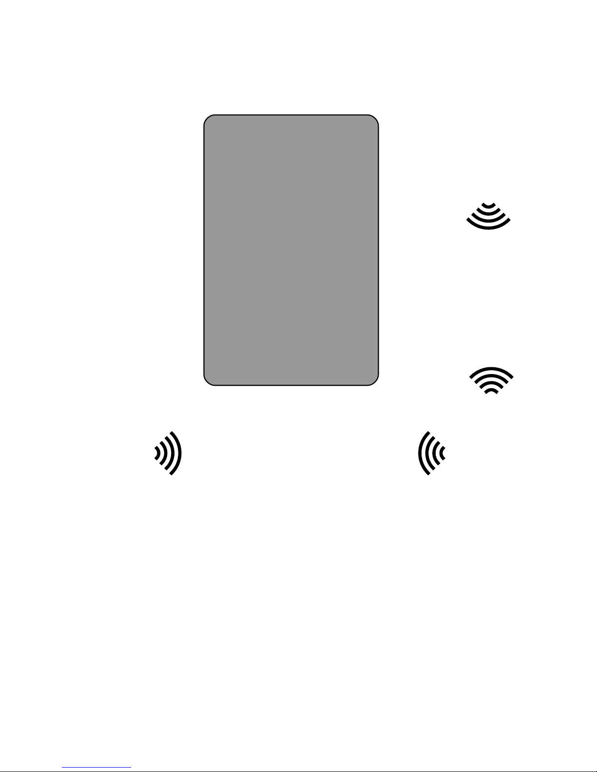
For environments with obstacles that do not allow the Central and Remote units to have line of sight, or which need
greater distances covered, a Repeater can be used. The diagram above shows the Repeater being used to get around
an environmental obstacle. The Repeater needs to have line of sight with both the Central and Remote units. The
Repeater needs only to be powered on; no other connections are necessary. The Repeater needs to be on the same
channel and network ID as the Central and Remote units.
Obstacle
Central
Remote
Repeater
Page 13

13
No Communication
When the Central and/or Remote unit is not communicating with its partner unit, the status LED will flash green/red. To
troubleshoot communication issues, check the following:
•
Power:
•
Both units must be powered.
•
Ensure proper power requirements are met: Unregulated Input 8 to 16Vdc @ 300mA max.
•
Installation:
•
There should be a direct line of sight between Central and Remote units (if there is no direct line of sight, a
Repeater unit is recommended).
•
The Central and Remote units should be installed level relative to each other.
•
Both the Central and Remote units should be mounted high enough to avoid interference from obstacles
(vehicles, trains, buildings, trees, etc.).
•
Metal mounting surfaces can affect communication as well as range. If use of a metal surface is
unavoidable, space unit as far from metal surface as possible using a non-metal spacer.
•
Antennas should both point up toward the sky (refer to Antenna Orientation, pg. 6).
•
In some cases an optimal mounting location can be selected by operating one of the units on a small 12V
battery and moving the location while observing the diagnostic LED indicators.
•
Configuration:
•
Ensure both Suprex units are set to the correct link type (see Configuration Mode, pgs. 7-9).
•
Ensure Suprex units are properly paired (see pgs. 25-26).
•
Ensure the Channel and Network ID settings on the Central and Remote units match (see Radio Configuration,
pgs. 25-26).
No Data / Invalid Data
If the access control panel is not receiving valid data, check the following:
•
Basic Equipment Check:
•
Ensure the reader and the access control panel data port are functional by directly connecting the reader to the
data port and passing card data.
•
Check Suprex circuit boards for any signs of visual damage, such as burnt traces, burnt components, or
browning of the PCB; these usually indicate misapplied power.
•
Wiring:
•
Ensure there is a common ground between the Remote unit and the card reader.
•
Ensure there is a common ground between the Central unit and the access control panel.
•
Ensure Wiegand data wires are correctly connected and not reversed.
•
Configuration:
•
Ensure both Suprex units are set to the correct interface type (see Configuration Mode, pgs. 7-9).
•
Ensure the access control panel is properly configured for the selected data format.
•
Data Voltage: For a Wiegand connection, ensure Data 0 and Data 1 pins on Central and Remote units are at 5V
relative to ground. The data pins can be as low as 4.4V before failing. If any Wiegand data pin is less than 4.4V, it is
necessary to identify which device is pulling down the voltage.
•
Disconnect the Suprex from the reader/panel.
•
Maintain power on the Suprex and the reader/panel.
•
Independently measure the voltages of the Wiegand data pins of the Suprex, and of the reader/panel. If one or
both devices have 4.3V or less, try enabling the pullup resistors on the Suprex by turning on DIP switch 5.
•
If internal pullup resistors do not work, try external pullup resistors (through-hole resistor 500 ohms - 2K ohms).
To install external pullup resistors, place one end of the through-hole resistor into the +5Vdc pin on the Suprex
unit; place the other end in the low-voltage Wiegand data pin (see pg. 5).
Cypress Suprex® RF Series - Troubleshooting
Page 14
14
INPUT
OUTPUT
Relay 1 Input (C)
Relay 1 COM, Relay 1 N.C., Relay 1 N.O. (R)
Relay 2 Input (C)
Relay 2 COM, Relay 2 N.C., Relay 2 N.O. (R)
Relay 3 Input (R)
Relay 3 COM, Relay 3 N.C., Relay 3 N.O. (C)
Relay 4 Input (R)
Relay 4 COM, Relay 4 N.C., Relay 4 N.O. (C)
LED Input (C)
LED Output (R)
Aux Input (R)
Aux Output (C)
The Cypress SPX-5631 or SPX-5641 provides additional data channels to support access control hardware such as door
strikes, tamper alarms, request to exit status, etc. These signals are sent to and from the Central and Remote units
without the need to run additional wiring. We refer to these data channels as Accessory I/O. Accessory I/O data channels
include Relay 1, Relay 2, Relay 3, Relay 4, LED, and AUX. Refer to the following pages (14-21) for details of each
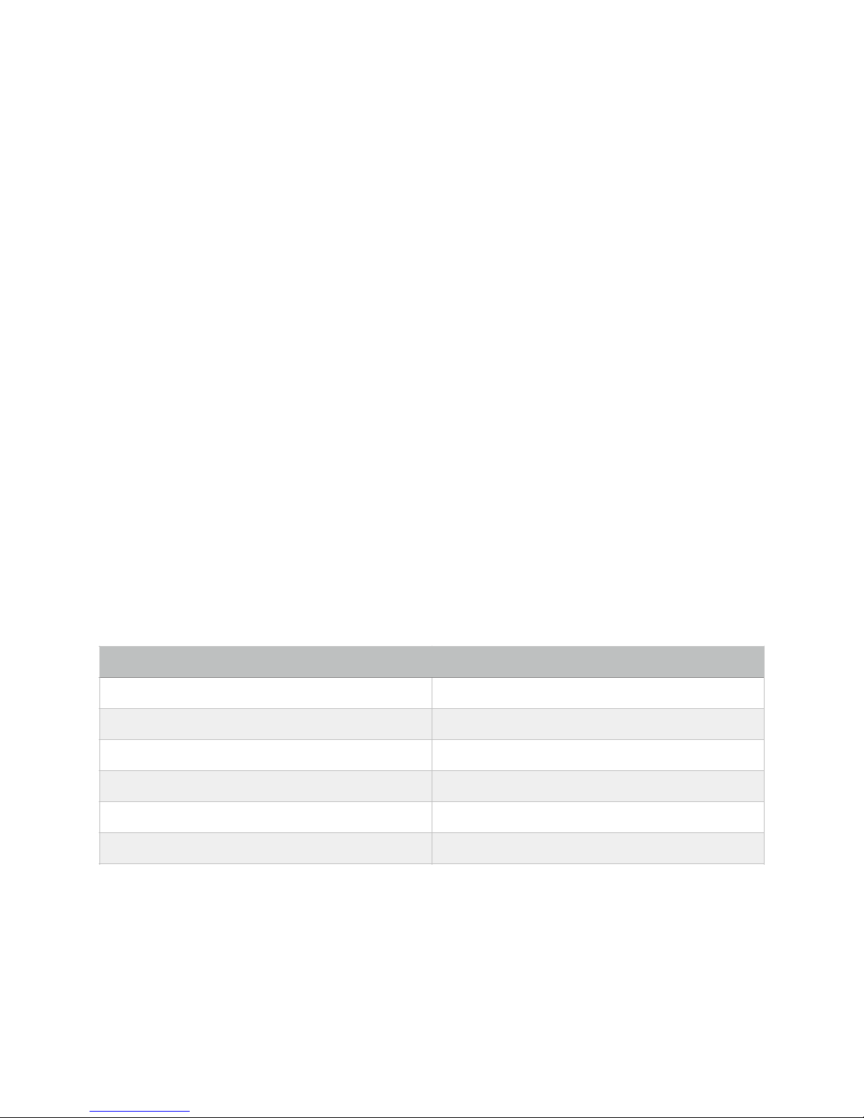
Accessory I/O operation and connection. Below is a table of the Accessory I/O pairs.
Relay I/O
The Relay I/O use active low inputs. When the Relay Inputs are floating (nothing connected) the inputs are set at 5V and
the corresponding Relay Outputs will have continuity between COM and N.C. When the Relay Input is set to 0Volts
(Ground) the input will activate the corresponding Relay Output. The Relay Outputs will have continuity between COM
and N.O. when the relay is activated and will hold this state for as long as the Relay Input is set to 0Volts. The Relay
Inputs can be tested by making a jumper connection to ground and monitoring the change in continuity of the Relay
Outputs.
Relay 3 functions as an Supervision relay when DIP switch 4 is on in Run Mode; a Supervision relay monitors the
condition of the communication link between the Central and Remote units. While in Supervision mode, Relay 3 is
activated when the communication link between the Central and Remote is established and functioning. Relay 3 will
deactivate (Alarm condition) when either the Relay 3 Input on the remote is active (pulled low) OR the Remote unit is
unable to communicate with the Central unit. See APPLICATION NOTE FOR DETAILS.
LED and AUX I/O
The LED and AUX I/O use active low inputs. When the inputs are floating (nothing connected) the associated output will
be set to a high level (5V). When the input is set to 0Volts (Ground) the input will activate its associated output. All
Accessory outputs are Open Collector type and will switch to Ground when activated and will hold this state as long as
the input is set to 0Volts. Each input will have an associated output. Inputs can be tested by making a jumper connection
to ground and monitoring the associated output.
Cypress Suprex® RF Series - Accessory I/O - Overview
Accessory I/O Pairs
(C) or (R) denotes which board the pin is located on.
Page 15
15
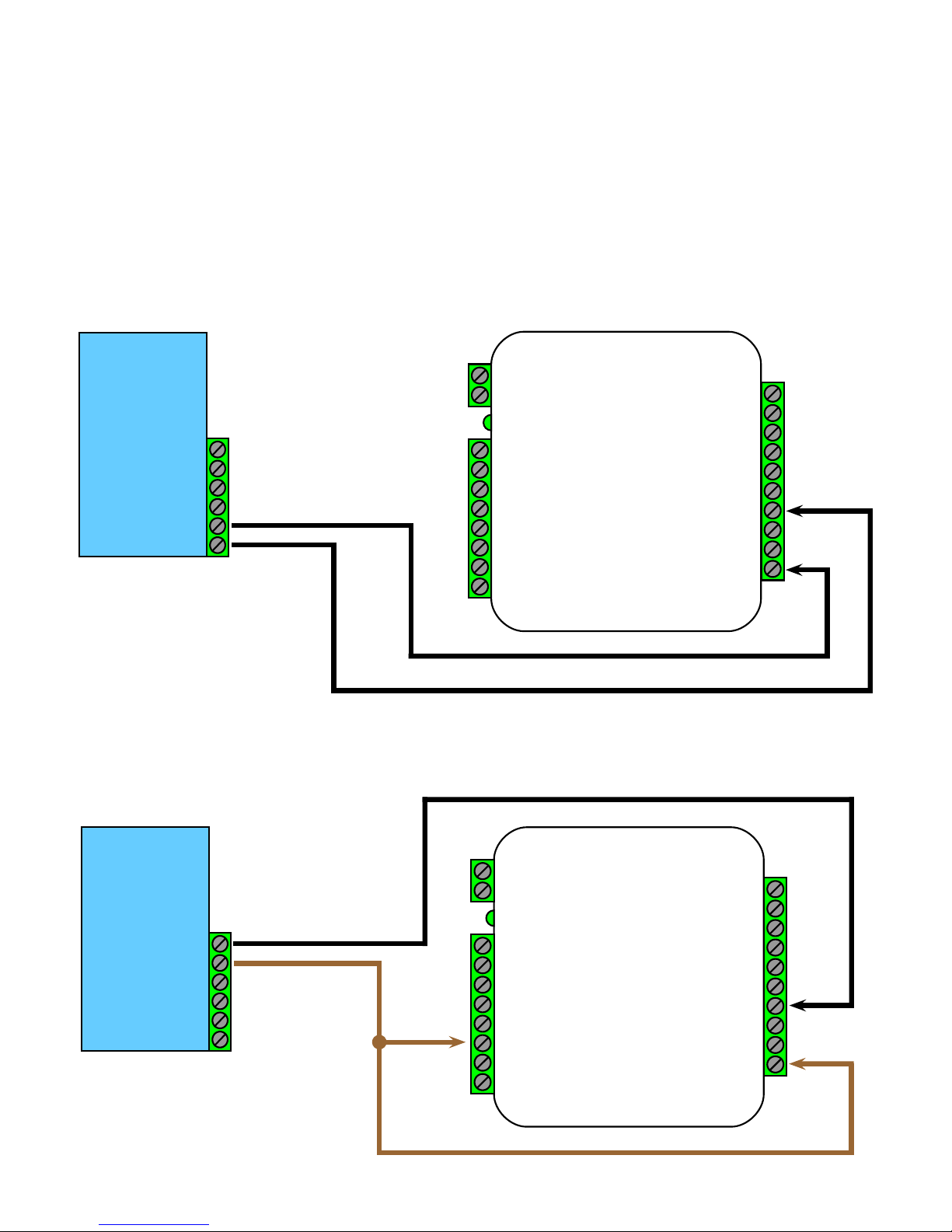
To activate the relay on the Remote unit, connect as shown below. These connections can be used to allow the Remote
relay to operate a DOOR STRIKE, GATE, or other locking hardware. The diagram below shows two methods of
triggering the relays. The first method uses a dry contact to trigger the relay. The second method shows the LED signal
triggering the LEDS.
Relays 1 and 2 are available for accessory outputs at the Remote end. Either relay can be used to provide the Door
Strike or Gate Activation function. This example uses Relay 1. The Relay Input pin is normally high (5V). When the
Relay Input pin is pulled low (0V) the corresponding relay on the Remote unit will be activated. When the relay is
activated, the Relay Output pins will change continuity from N.C. and COM to N.O. and COM (not shown in diagram).
Cypress Suprex® RF Series - Accessory I/O - Central Relay Inputs
Relay Wiring Example - Door Strike Follows LED
Relay Input Wiring Example - Door Strike Follows Dry Contact
Ground
LED Out
Data1
Data 0
N.O.
COM
Access
Control
Panel
Ground
LED Out
Data1
Data 0
N.O.
COM
Access
Control
Panel
+8 to +16 VDC
Ground
exp(+)
exp(-)
+5V Out
P R 4
P R 3
LED In
D1/Data Out
D0/Clock Out
Relay 4 N.O.
Relay 4 Com
Relay 4 N.C.
Relay 3 N.O.
Relay 3 Com
Relay 3 N.C.
Ground
Aux Output
Relay 2 Input
Relay 1 Input
+8 to +16 VDC
Ground
exp(+)
exp(-)
+5V Out
P R 4
P R 3
LED In
D1/Data Out
D0/Clock Out
Relay 4 N.O.
Relay 4 Com
Relay 4 N.C.
Relay 3 N.O.
Relay 3 Com
Relay 3 N.C.
Ground
Aux Output
Relay 2 Input
Relay 1 Input
Central
Central
Page 16
16
Cypress Suprex® RF Series - Accessory I/O - Relay 1 & 2 I/O
Relay 2 I/O Diagram
+8 to +16 VDC
Ground
exp(+)
exp(-)
+5V Out
P R 4
P R 3
LED In
D1/Data Out
D0/Clock Out
Relay 4 N.O.
Relay 4 Com
Relay 4 N.C.
Relay 3 N.O.
Relay 3 Com
Relay 3 N.C.
Ground
Aux Output
Relay 2 Input
Relay 1 Input
Central
+8 to +16 VDC
Ground
exp(+)
exp(-)
+5V Out
Relay 4 Input
Relay 3 Input
LED Out
D1/Data In
D0/Clock In
Relay 2 N.O.
Relay 2 Com
Relay 2 N.C.
Relay 1 N.O.
Relay 1 Com
Relay 1 N.C.
Ground
Aux Input
Not Used
Not Used
Remote
+8 to +16 VDC
Ground
exp(+)
exp(-)
+5V Out
Relay 4 Input
Relay 3 Input
LED Out
D1/Data In
D0/Clock In
Relay 2 N.O.
Relay 2 Com
Relay 2 N.C.
Relay 1 N.O.
Relay 1 Com
Relay 1 N.C.
Ground
Aux Input
Not Used
Not Used
Remote
+8 to +16 VDC
Ground
exp(+)
exp(-)
+5V Out
P R 4
P R 3
LED In
D1/Data Out
D0/Clock Out
Relay 4 N.O.
Relay 4 Com
Relay 4 N.C.
Relay 3 N.O.
Relay 3 Com
Relay 3 N.C.
Ground
Aux Output
Relay 2 Input
Relay 1 Input
Central
Relay 1 I/O Diagram
+8 to +16 VDC
Ground
exp(+)
exp(-)
+5V Out
P R 4
P R 3
LED In
D1/Data Out
D0/Clock Out
Relay 4 N.O.
Relay 4 Com
Relay 4 N.C.
Relay 3 N.O.
Relay 3 Com
Relay 3 N.C.
Ground
Aux Output
Relay 2 Input
Relay 1 Input
Central
+8 to +16 VDC
Ground
exp(+)
exp(-)
+5V Out
Relay 4 Input
Relay 3 Input
LED Out
D1/Data In
D0/Clock In
Relay 2 N.O.
Relay 2 Com
Relay 2 N.C.
Relay 1 N.O.
Relay 1 Com
Relay 1 N.C.
Ground
Aux Input
Not Used
Not Used
Remote
+8 to +16 VDC
Ground
exp(+)
exp(-)
+5V Out
P R 4
P R 3
LED In
D1/Data Out
D0/Clock Out
Relay 4 N.O.
Relay 4 Com
Relay 4 N.C.
Relay 3 N.O.
Relay 3 Com
Relay 3 N.C.
Ground
Aux Output
Relay 2 Input
Relay 1 Input
Central
+8 to +16 VDC
Ground
exp(+)
exp(-)
+5V Out
Relay 4 Input
Relay 3 Input
LED Out
D1/Data In
D0/Clock In
Relay 2 N.O.
Relay 2 Com
Relay 2 N.C.
Relay 1 N.O.
Relay 1 Com
Relay 1 N.C.
Ground
Aux Input
Not Used
Not Used
Remote
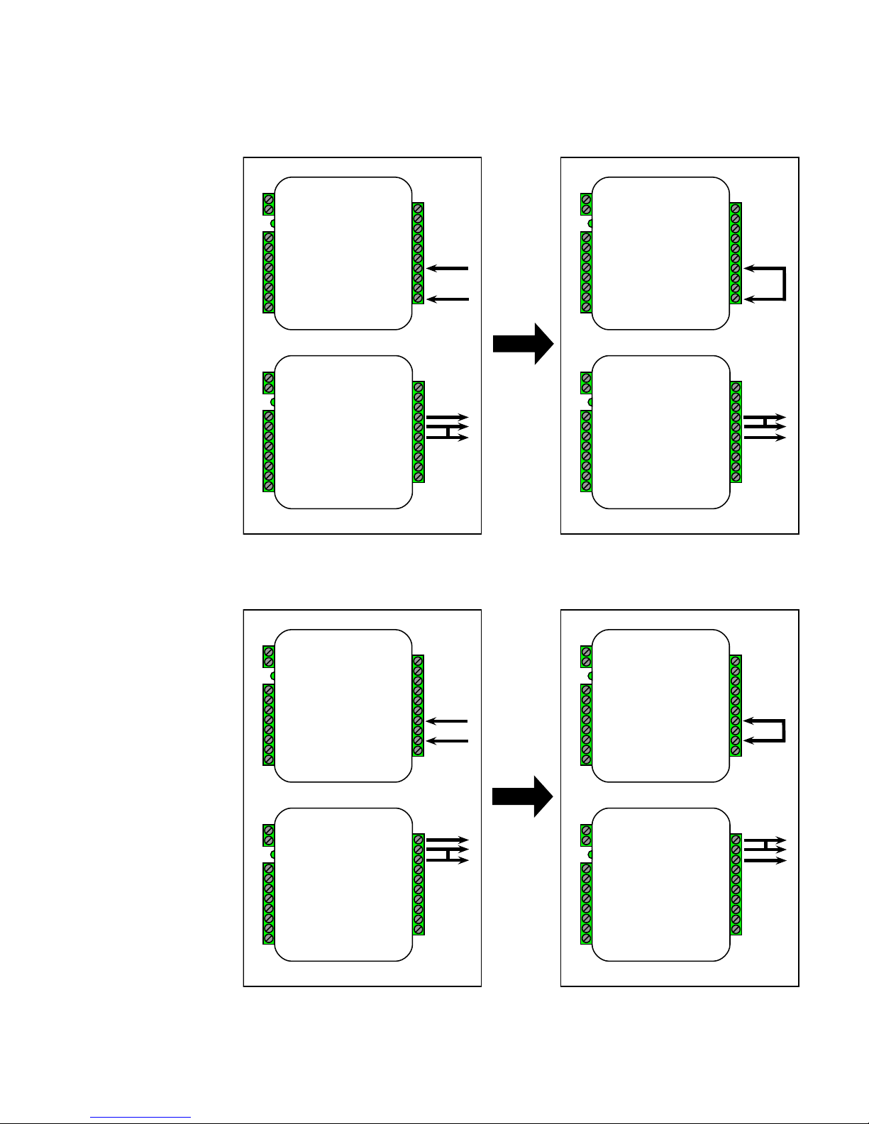
This diagram shows how
the state of the the Relay 2
Outputs change the as
Relay 2 Input is set to
0Volts (connected to
Ground) using a jumper
connection. The left side
shows that when Relay 2
Input is not set to 0Volts,
Relay 2 COM and Relay 2
N.C have continuity. The
right side shows that when
Relay 2 Input is set to
0Volts, Relay 2 COM and
Relay 2 N.O. have
continuity.
This diagram illustrates
how the state of the Relay
1 Outputs change the as
Relay 1 Input is set to
0Volts (connected to
Ground) using a jumper
connection.
The left side illustrates that
when Relay 1 Input is not
set to 0Volts, Relay 1
COM and Relay 1 N.C
have continuity. The right
side shows that when
Relay 1 Input is set to
0Volts, Relay 1 COM and
Relay 1 N.O. have
continuity.
Page 17
17
Cypress Suprex® RF Series - Accessory I/O - Remote Relay Inputs
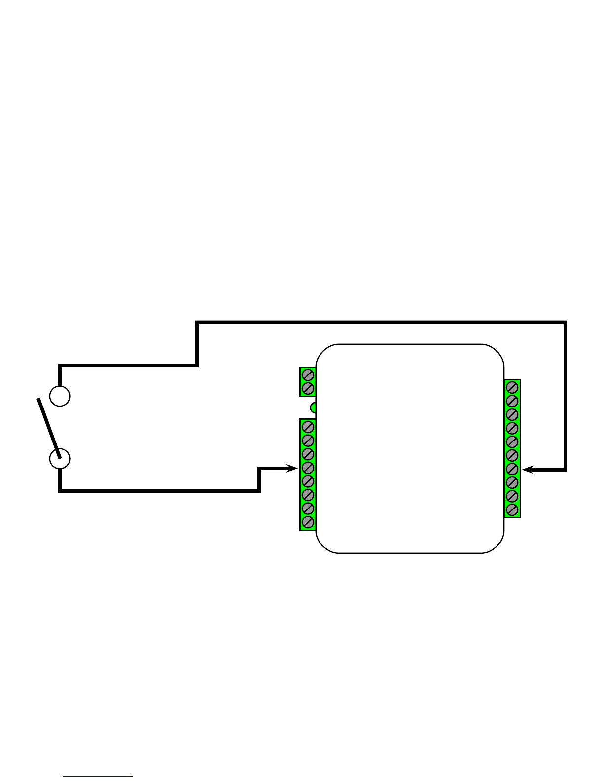
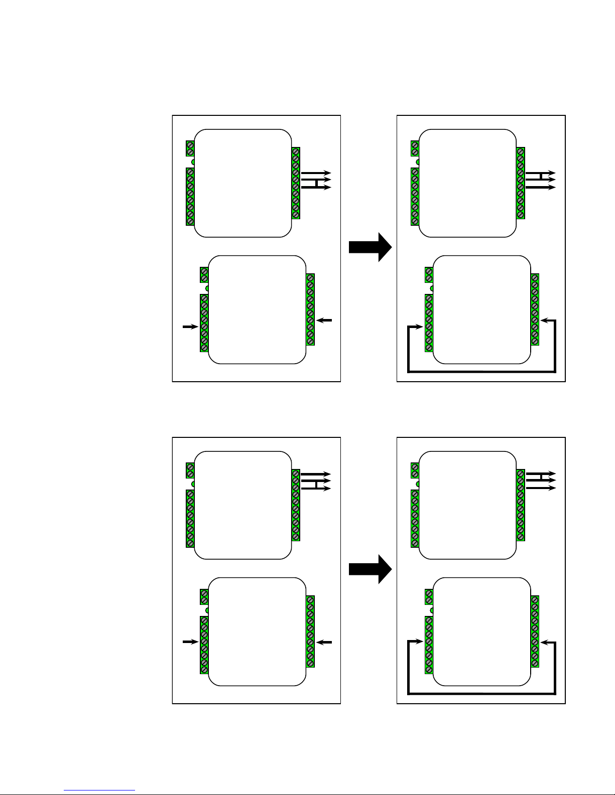
To activate the relay on the Central unit, connect as shown below. These connections can be used to operate a REX
switch or other signals that need to go to the access panel.
Relays 3 and 4 are available for accessory outputs at the Central end. Either Relay 3 or Relay 4 can be used. This
example uses Relay 4. The Relay Input pin is normally high (5V). When the Relay Input pin is pulled low (0Volts) the
corresponding relay on the Remote unit will be activated. When the relay is activated, the relay output pins will change
continuity from N.C. and COM to N.O. and COM (not shown in diagram).
Relay 3 can used to send signals to the access panel while Supervision mode is active, but it is important to remember
that the outputs will be reversed. When Supervision mode is active and the Relay 3 Input pin is normal (5V) the relay
output pins will have continuity between N.O. and COM. When Supervision mode is active and the Relay 3 Input pin is
active (0Volts) the relay output pins will have continuity between N.C. and COM.
Relay Wiring Example - REX Switch
+8 to +16 VDC
Ground
exp(+)
exp(-)
+5V Out
Relay 4 Input
Relay 3 Input
LED Out
D1/Data In
D0/Clock In
Relay 2 N.O.
Relay 2 Com
Relay 2 N.C.
Relay 1 N.O.
Relay 1 Com
Relay 1 N.C.
Ground
Aux Input
Not Used
Not Used
Remote
Page 18
18
Cypress Suprex® RF Series - Accessory I/O - Relay 3 & 4 I/O
Relay 4 I/O Diagram
+8 to +16 VDC
Ground
exp(+)
exp(-)
+5V Out
P R 4
P R 3
LED In
D1/Data Out
D0/Clock Out
Relay 4 N.O.
Relay 4 Com
Relay 4 N.C.
Relay 3 N.O.
Relay 3 Com
Relay 3 N.C.
Ground
Aux Output
Relay 2 Input
Relay 1 Input
Central
+8 to +16 VDC
Ground
exp(+)
exp(-)
+5V Out
P R 4
P R 3
LED In
D1/Data Out
D0/Clock Out
Relay 4 N.O.
Relay 4 Com
Relay 4 N.C.
Relay 3 N.O.
Relay 3 Com
Relay 3 N.C.
Ground
Aux Output
Relay 2 Input
Relay 1 Input
Central
+8 to +16 VDC
Ground
exp(+)
exp(-)
+5V Out
Relay 4 Input
Relay 3 Input
LED Out
D1/Data In
D0/Clock In
Relay 2 N.O.
Relay 2 Com
Relay 2 N.C.
Relay 1 N.O.
Relay 1 Com
Relay 1 N.C.
Ground
Aux Input
Not Used
Not Used
Remote
+8 to +16 VDC
Ground
exp(+)
exp(-)
+5V Out
Relay 4 Input
Relay 3 Input
LED Out
D1/Data In
D0/Clock In
Relay 2 N.O.
Relay 2 Com
Relay 2 N.C.
Relay 1 N.O.
Relay 1 Com
Relay 1 N.C.
Ground
Aux Input
Not Used
Not Used
Remote
Relay 3 I/O Diagram
+8 to +16 VDC
Ground
exp(+)
exp(-)
+5V Out
P R 4
P R 3
LED In
D1/Data Out
D0/Clock Out
Relay 4 N.O.
Relay 4 Com
Relay 4 N.C.
Relay 3 N.O.
Relay 3 Com
Relay 3 N.C.
Ground
Aux Output
Relay 2 Input
Relay 1 Input
Central
+8 to +16 VDC
Ground
exp(+)
exp(-)
+5V Out
P R 4
P R 3
LED In
D1/Data Out
D0/Clock Out
Relay 4 N.O.
Relay 4 Com
Relay 4 N.C.
Relay 3 N.O.
Relay 3 Com
Relay 3 N.C.
Ground
Aux Output
Relay 2 Input
Relay 1 Input
Central
+8 to +16 VDC
Ground
exp(+)
exp(-)
+5V Out
Relay 4 Input
Relay 3 Input
LED Out
D1/Data In
D0/Clock In
Relay 2 N.O.
Relay 2 Com
Relay 2 N.C.
Relay 1 N.O.
Relay 1 Com
Relay 1 N.C.
Ground
Aux Input
Not Used
Not Used
Remote
+8 to +16 VDC
Ground
exp(+)
exp(-)
+5V Out
Relay 4 Input
Relay 3 Input
LED Out
D1/Data In
D0/Clock In
Relay 2 N.O.
Relay 2 Com
Relay 2 N.C.
Relay 1 N.O.
Relay 1 Com
Relay 1 N.C.
Ground
Aux Input
Not Used
Not Used
Remote
This diagram shows how
the state of the the Relay 3
Outputs change the as
Relay 3 Input is set to
0Volts (connected to
Ground) using a jumper
connection. The left side
shows that when Relay 3
Input is not set to 0Volts,
Relay 3 COM and Relay 3
N.C have continuity. The
right side shows that when
Relay 3 Input is set to
0Volts, Relay 3 COM and
Relay 3 N.O. have
continuity.
This diagram shows how
the state of the the Relay 4
Outputs change the as
Relay 4 Input is set to
0Volts (connected to
Ground) using a jumper
connection. The left side
shows that when Relay 4
Input is not set to 0Volts,
Relay 4 COM and Relay 1
N.C have continuity. The
right side shows that when
Relay 4 Input is set to
0Volts, Relay 4 COM and
Relay 4 N.O. have
continuity.
Page 19
19
Cypress Suprex® RF Series - Accessory I/O - LED I/O
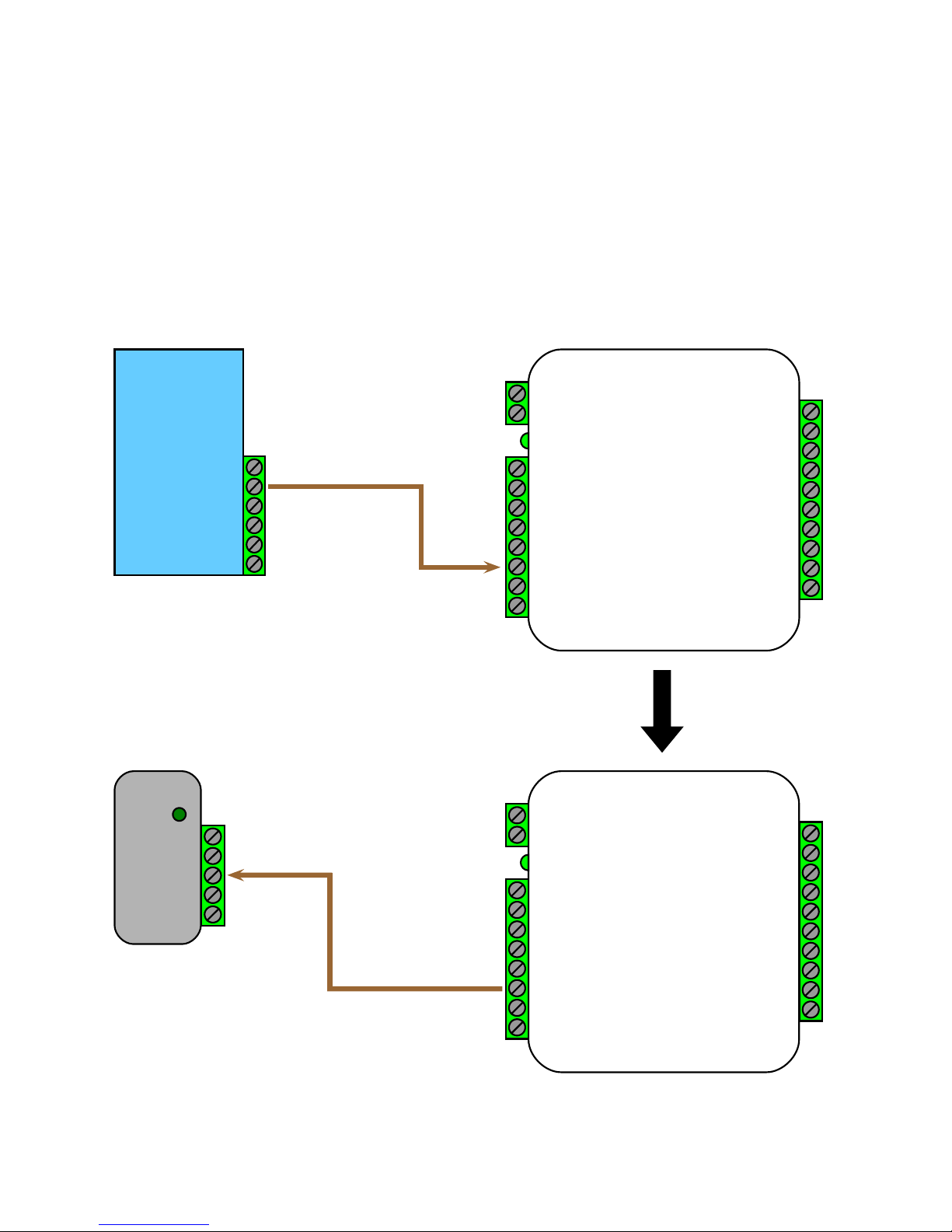
For access control panels with a LED Output signal, the SPX-5631 / SPX-5641 is able to transmit this signal to the
reader with the LED Input and LED Output pins. The LED In pin is a digital input and the LED Out pin is a digital output.
The LED In pin has two states, 5V (high or normal) and 0Volts (low or active). The LED Out pin will mirror the state of the
LED In pin.
The LED I/O Signal Diagram below shows how this signal is passed through he SPX-5631 / SPX-5641.
Ground
LED Out
Data1
Data 0
N.O.
COM
Access
Control
Panel
Card
Reader
Power
Ground
LED IN
Data 1
Data 0
LED I/O Signal Diagram
+8 to +16 VDC
Ground
exp(+)
exp(-)
+5V Out
Relay 4 Input
Relay 3 Input
LED Out
D1/Data In
D0/Clock In
Relay 2 N.O.
Relay 2 Com
Relay 2 N.C.
Relay 1 N.O.
Relay 1 Com
Relay 1 N.C.
Ground
Aux Input
Not Used
Not Used
+8 to +16 VDC
Ground
exp(+)
exp(-)
+5V Out
P R 4
P R 3
LED In
D1/Data Out
D0/Clock Out
Relay 4 N.O.
Relay 4 Com
Relay 4 N.C.
Relay 3 N.O.
Relay 3 Com
Relay 3 N.C.
Ground
Aux Output
Relay 2 Input
Relay 1 Input
Central
Remote
Page 20
20
Cypress Suprex® RF Series - Accessory I/O - AUX I/O
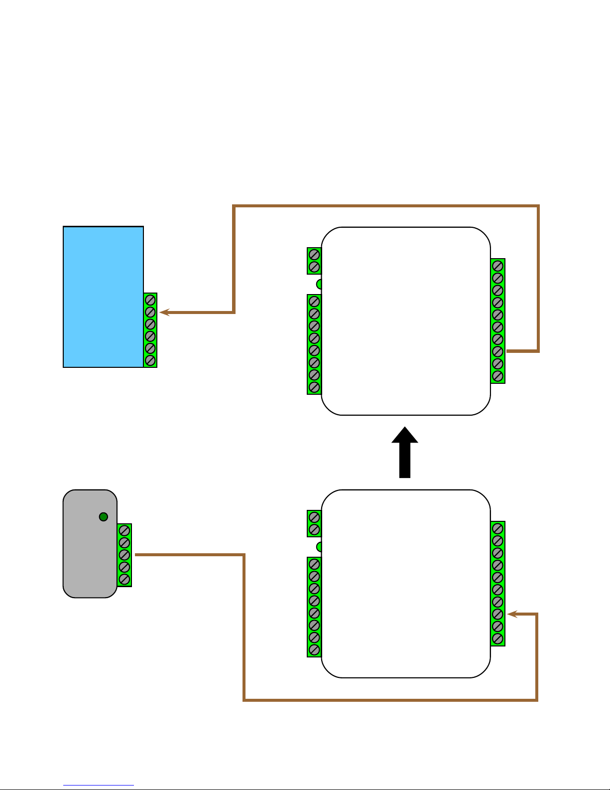
The SPX-5631 / SPX-5641 has an auxiliary I/O signal going from the reader side to the panel side. The SPX-5631 /
SPX-5641 is able to transmit this signal to the panel with the AUX Input and AUX Output pins. The AUX In pin is a digital
input and the AUX Out pin is a digital output. The AUX In pin has two states, 5V (high or normal) and 0Volts (low or active).
The AUX Out pin will mirror the state of the AUX In pin.
The AUX I/O Signal Diagram below shows how this signal is passed through the SPX-5631 / SPX-5641.
AUX I/O Signal Diagram
Ground
Input
Data1
Data 0
N.O.
COM
Access
Control
Panel
Card
Reader
Power
Ground
Output
Data 1
Data 0
+8 to +16 VDC
Ground
exp(+)
exp(-)
+5V Out
Relay 4 Input
Relay 3 Input
LED Out
D1/Data In
D0/Clock In
Relay 2 N.O.
Relay 2 Com
Relay 2 N.C.
Relay 1 N.O.
Relay 1 Com
Relay 1 N.C.
Ground
Aux Input
Not Used
Not Used
+8 to +16 VDC
Ground
exp(+)
exp(-)
+5V Out
P R 4
P R 3
LED In
D1/Data Out
D0/Clock Out
Relay 4 N.O.
Relay 4 Com
Relay 4 N.C.
Relay 3 N.O.
Relay 3 Com
Relay 3 N.C.
Ground
Aux Output
Relay 2 Input
Relay 1 Input
Central
Remote
Page 21
21
The following applies to these products: SPX-5631 and SPX-5641.
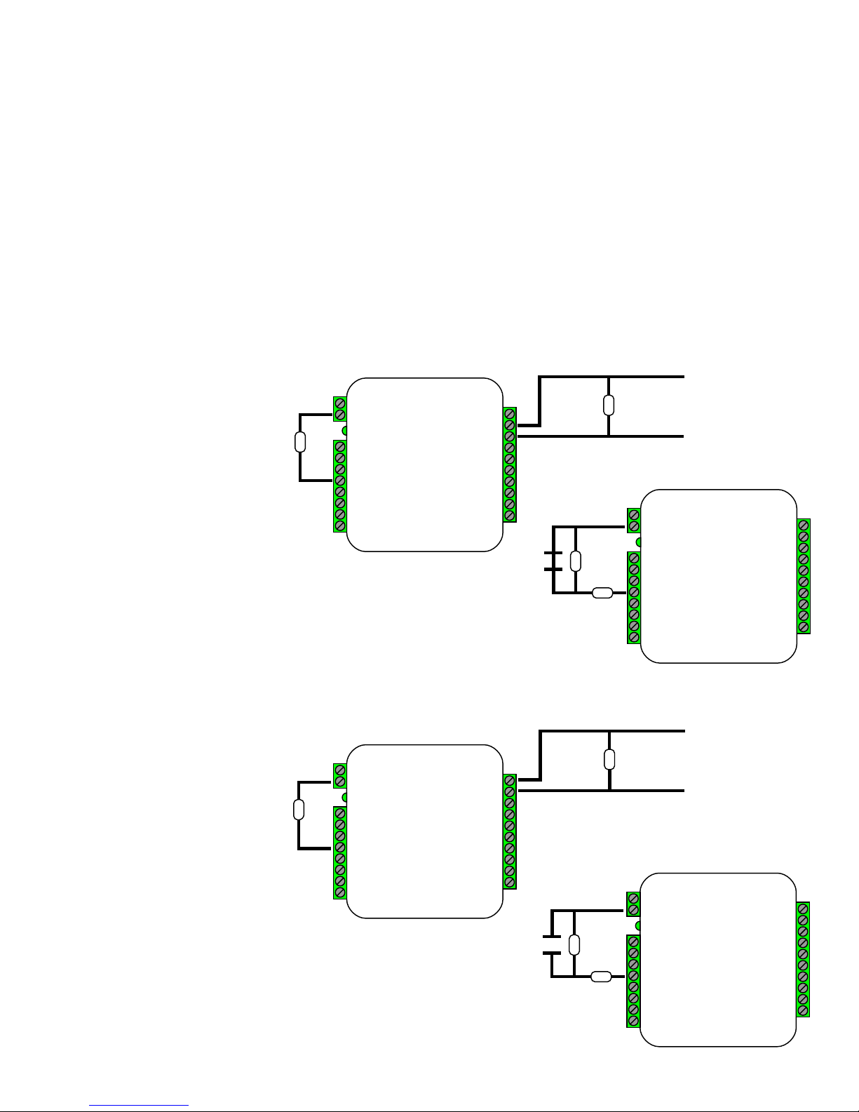
This application note describes the connections necessary to convey supervised contact status over a Suprex®. The
configurations described in this application note should apply to most panels which utilize supervised contacts. When
connected as described, the Suprex® provides a supervised signal to the panel interface by reading the supervised status
of the contacts connected to the Suprex® Remote unit.
Theory of operation: The access control panel is looking for a certain value of resistance connected to the supervised
contact terminals. The Suprex® Central unit will provide these resistance values locally at the panel so that the correct
supervised status is maintained. At the same time, the Remote unit must maintain supervision of the wires connected to
the relays and switches connected to the remote access point. The contact supervision is provided by the Remote unit.
The Suprex® system does this by comparing the value of programming resistor at the Central unit with the resistance seen
at the Remote interface terminals. When there is a difference in the two values, the Relay on the Central unit is activated.
There are two different
examples. One example is
monitoring a normally closed
contact at the Remote unit, and
the other example is monitoring
a normally open contact at the
Remote unit. In the examples
given, a normally closed
contact will require a
programming resistor of 1K and
a normally open contact will
require a programming resistor
of 2K. Other resistor values can
be used, but 1K resistors are
the most common. Other
resistance values will require
different value(s) for the
programming resistor(s).
+8 to +16 VDC
Ground
exp(+)
exp(-)
+5V Out
P R 4
P R 3
LED In
D1/Data Out
D0/Clock Out
Relay 4 N.O.
Relay 4 Com
Relay 4 N.C.
Relay 3 N.O.
Relay 3 Com
Relay 3 N.C.
Ground
Aux Output
Relay 2 Input
Relay 1 Input
+8 to +16 VDC
Ground
exp(+)
exp(-)
+5V Out
Relay 4 Input
Relay 3 Input
LED In
D1/Data In
D0/Clock In
Relay 2 N.O.
Relay 2 Com
Relay 2 N.C.
Relay 1 N.O.
Relay 1 Com
Relay 1 N.C.
Ground
Aux Input
Not Used
Not Used
+8 to +16 VDC
Ground
exp(+)
exp(-)
+5V Out
P R 4
P R 3
LED In
D1/Data Out
D0/Clock Out
Relay 4 N.O.
Relay 4 Com
Relay 4 N.C.
Relay 3 N.O.
Relay 3 Com
Relay 3 N.C.
Ground
Aux Output
Relay 2 Input
Relay 1 Input
Central
Remote
Remote
Central
Normally Closed Contact
Normally Open Contact
1K
1K
Input +
Input -
+8 to +16 VDC
Ground
exp(+)
exp(-)
+5V Out
Relay 4 Input
Relay 3 Input
LED In
D1/Data In
D0/Clock In
Relay 2 N.O.
Relay 2 Com
Relay 2 N.C.
Relay 1 N.O.
Relay 1 Com
Relay 1 N.C.
Ground
Aux Input
Not Used
Not Used
1K
1K
2K
1K
1K
1K
Input -
Input +
Application Note on using Supervised contacts with the Suprex® RF Series
Page 22

22
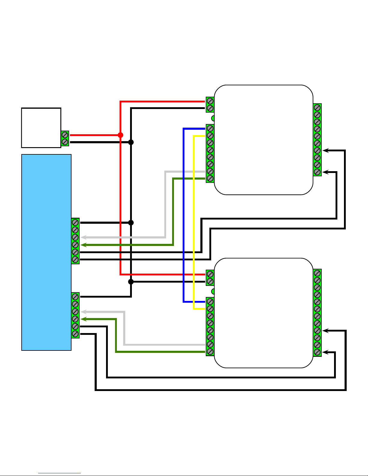
EXP-2000 Expansion Modules allow additional readers to connect to the access control panel using a single Suprex® RF
link. This is useful at door/gate locations with more than one card reader, such as in/out door readers or high/low gate
readers. The Suprex® RF can accommodate a maximum of 8 readers with the use of 7 EXP-2000 Expansion Modules.
Each reader requires its own data port on the access control panel.
Before using EXP-2000 Expansion modules with the Suprex® system, it will be necessary to perform a short configuration
process. This process determines how many expansion modules will be used with the Suprex® system. Each Suprex®
link can support up to 7 expansion modules.
Operation Overview:
The EXP-2000 pair of units is connected to the Suprex® pair of units via an RS-485 connection. The EXP Central units
will be daisy-chained off the Suprex® Central RS-485 port (labeled EXP+ and EXP- ). The EXP Remote units will be
daisy-chained off the Suprex® Remote unit RS-485 port (also labeled EXP+ and EXP- ). The only link between the
reader/gate location and the panel will be the Suprex® link; in this case, the wireless link.
The Suprex® and EXP-2000 Expansion Modules operate on an addressing scheme. The Suprex® pair is always address
0. The first EXP pair will be address 1, the second EXP pair will be address 2, etc. (see pgs. 7-9). When configuring the
Suprex® pair to work with the EXPs, the Central and Remote units must be told how many EXP pairs they will be working
with. The Central and Remote units of each EXP pair must be configured with their address numbers.
Setup Process: By default, Suprex® units are not configured to accommodate EXP-2000 expansion modules. To
reconfigure the Suprex® units, follow this process for both the Central and Remote units.
•
The Suprex® Central and Remote units must be configured with the total number of EXP pairs being used.
•
This is configured in the Run Mode settings and is controlled by DIP switches 6, 7, and 8.
•
Change settings on both the Suprex® Central and Remote units, as shown on pgs 7-9.
•
The EXP-2000 Expansion Module pairs need to be properly addressed with their address number.
•
The EXP address is configured by using DIP switches 6, 7, and 8 on the EXP-2000 Central and Remote units.
•
The first EXP pair will be address 1, the second EXP pair will be address 2, etc. (see pgs. 7-9).
•
Set DIP Switch 8 on the EXP Central and Remote units to set to address 1.
•
Set DIP Switch 7 on the EXP Central and Remote units to set to address 2.
•
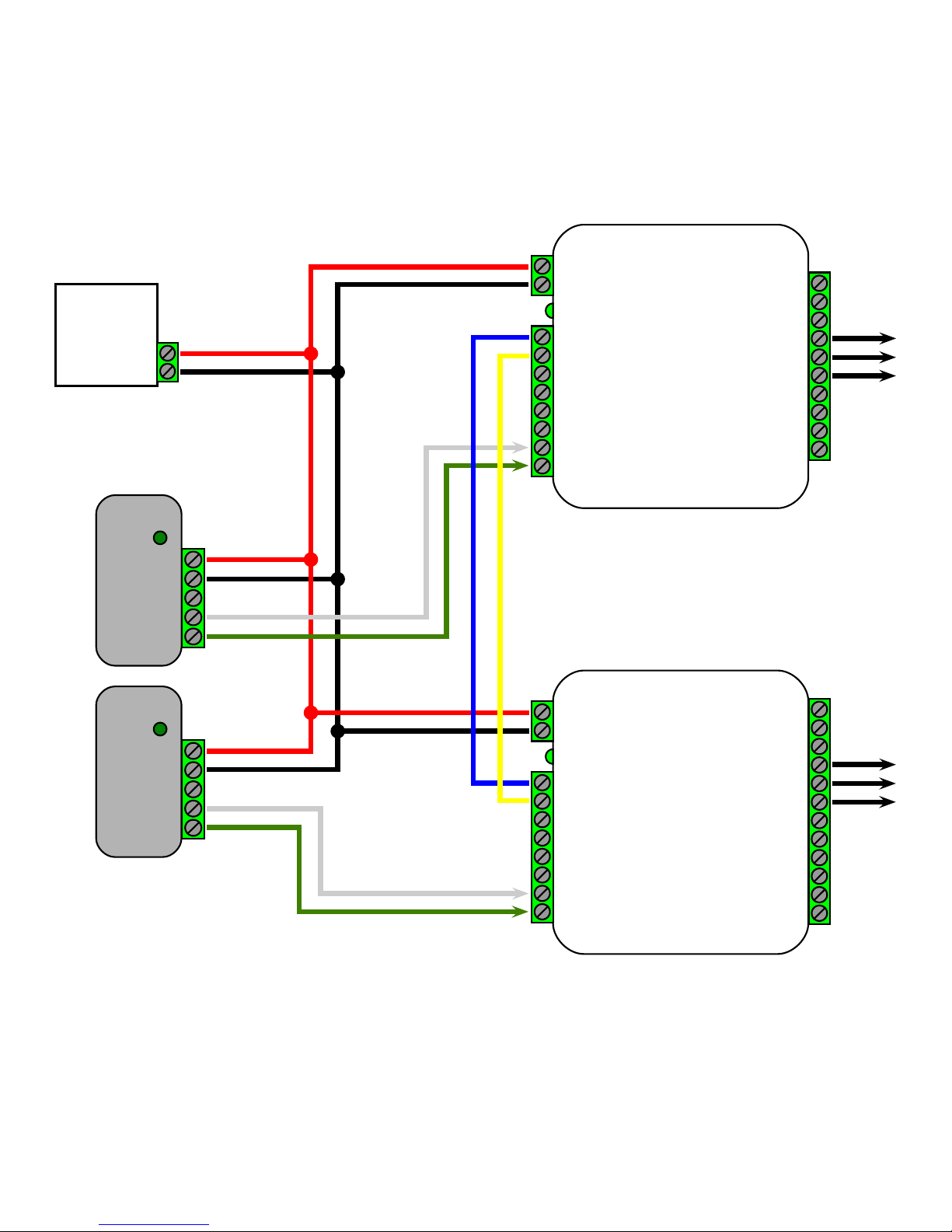
Connect the EXP Expansion Modules into the system as indicated in the wiring diagrams on pages 23 and 24.
Suprex® Operation with Expansion Modules: Using EXP Expansion Modules does not change the normal
function of the Suprex®, with these exceptions:
•
EXP Expansion Modules are compatible only with the Wiegand interface type (does not apply to Wiegand No Filter)
•
If the Suprex® Supervision relay is enabled, the Supervision relay will deactivate (indicate alarm state) if the
communication link fails between the Suprex® pair or ANY of the the EXP pairs. (To enable Supervision relay, see Run
Mode settings, pgs. 7-9.)
•
LED Indicators with Suprex® Pair:
•
Suprex® Central or Remote status LED is solid green in Run Mode: one or more of the connected EXP units is not
communicating properly. Ensure all EXP units are powered and correctly wired.
•
EXP status LED is solid red: EXP unit is not properly communicating with the Suprex® unit. Ensure the Suprex® unit
is powered and wired correctly.
•
EXP status LED is flashing green: EXP unit is properly communicating with the Suprex®.
•
The EXP-2000 Central and Remote pair will be functionally similar to the standard Cypress SPX-1300 Suprex® system.
For more details, see the EXP-2000 manual.
Cypress Suprex® RF Series - Using EXP-2000 Expansion Modules
Page 23
23
Cypress Suprex® RF Series - Suprex Central and EXP Central Wiring Diagram
+8 to +16 VDC
Ground
exp(+)
exp(-)
+5V Out
P R 4
P R 3
LED In
D1/Data Out
D0/Clock Out
Relay 4 N.O.
Relay 4 Com
Relay 4 N.C.
Relay 3 N.O.
Relay 3 Com
Relay 3 N.C.
Ground
Aux Output
Relay 2 Input
Relay 1 Input
+8 to +16 VDC
Ground
exp(+)
exp(-)
+5V Out
P R 2
P R 1
LED In
D1/Data Out
D0/Clock Out
Relay 4 N.O.
Relay 4 Com
Relay 4 N.C.
Relay 3 N.O.
Relay 3 Com
Relay 3 N.C.
RS232 Out
RS232 In
Ground
Aux Out
Relay 2 Input
Relay 1 Input
DC Power
Supply
Power
Ground
Ground
LED Out
Data1
Data 0
N.O.
COM
Access
Control
Panel
Ground
LED Out
Data1
Data 0
N.O.
COM
Port 1
Port 2
Suprex
Central
EXP
Central
Page 24
24
See EXP-2000 Manual for further setup instructions.
Cypress Suprex® RF Series - Suprex Remote and EXP Remote Wiring Diagram
DC Power
Supply
Power
Ground
+8 to +16 VDC
Ground
exp(+)
exp(-)
+5V Out
Relay 4 Input
Relay 3 Input
LED Out
D1/Data In
D0/Clock In
Relay 2 N.O.
Relay 2 Com
Relay 2 N.C.
Relay 1 N.O.
Relay 1 Com
Relay 1 N.C.
Ground
Aux Input
Not Used
Not Used
+8 to +16 VDC
Ground
exp(+)
exp(-)
+5V Out
Relay 4 Input
Relay 3 Input
LED Out
D1/Data In
D0/Clock In
Relay 2 N.O.
Relay 2 Com
Relay 2 N.C.
Relay 1 N.O.
Relay 1 Com
Relay 1 N.C.
RS232 Out
RS232 In
Ground
Aux In
Not Used
Not Used
Suprex
Remote
EXP
Remote
Card
Reader
Power
Ground
LED IN
Data 1
Data 0
Card
Reader
Power
Ground
LED IN
Data 1
Data 0
Page 25
25
Channel
1234
0
1
2
3
4
5
6
7
8
9
10
11
12
13
14
15
Network
567
1778
1779
1780
1781
1782
1783
1784
1785
OFF
ON
Switch position
Cypress Suprex® RF Series - Radio Configuration
RF
Module
LEDs
DIP Switch
Pairing
Normal Mode
Pairing Mode
10
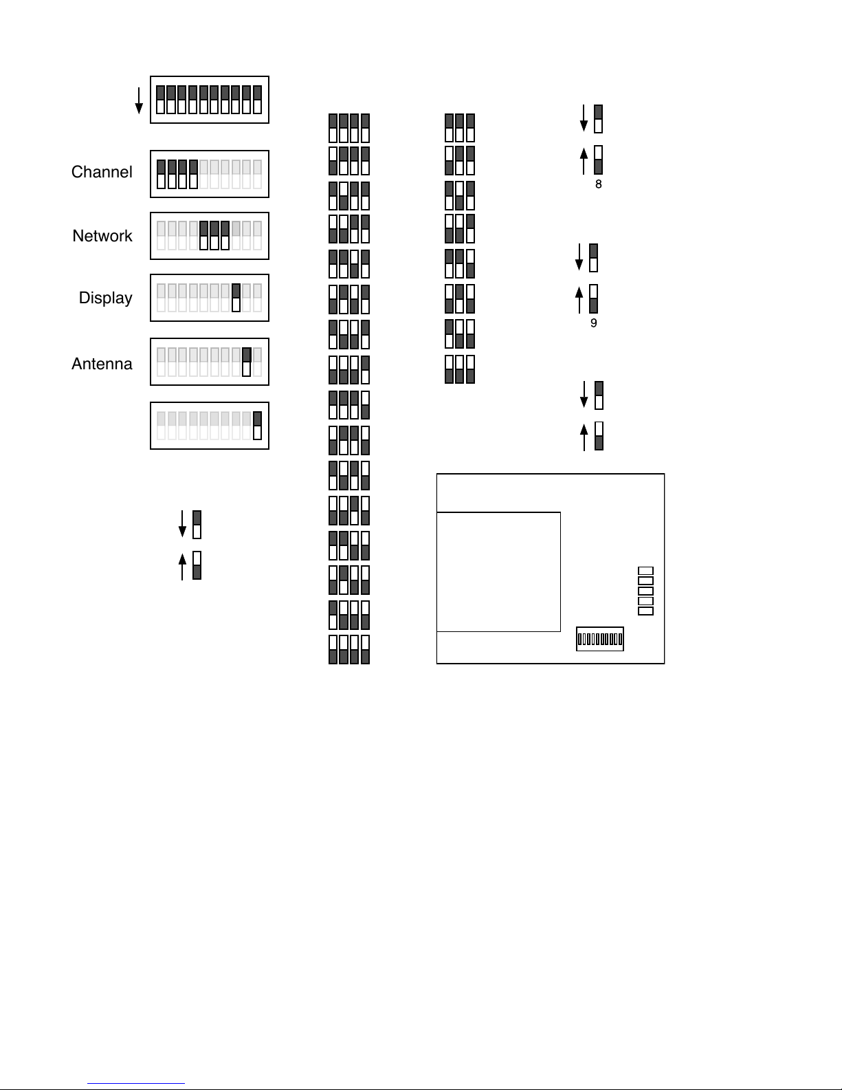
The diagrams above show the 10 RF Daughter Board DIP switches and their functions. Using these DIP switches the
user can change the wireless channel, network number, LED Display, Antenna Selection, and pair the Central and
Remote units.
Antenna
All Off
12345678910
Channel
Network
Display
Pairing
Wireless Channel Selection
DIP switches 1-4 control the wireless channel. Refer to the channel diagram above to set the DIP switches to the correct
configuration for the desired channel. The Central and Remote units will be set to channel 4 by default. Both the Central
and Remote unit need to be on the same channel and network in order to communicate. When a change is made to the
channel selection, the unit will need to be power cycled for the change to take effect.
Note: Channels 0,1, and 15 are reserved and should not be used by the enduser, leaving channels 2-14 (13 channels)
for user operation.
Wireless Network ID Selection
DIP switches 5-7 control the wireless network. Refer to the network diagram above to set the DIP switches to the correct
configuration for the desired network ID. The Central and Remote units will be set to network ID 1778 by default. Both
the Central and Remote unit need to be on the same channel and network ID in order to communicate. When a change
is made to network ID selection, the unit will need to be power cycled for the change to take effect.
Meter Display
Link Quality
Energy
Antenna Select
Chip Antenna
External Dipole Antenna
Page 26
26
time
Pairing Mode
Switch 10
time
10
Signal Strength Meter
No Signal
-90dbm to -80dbm
-80dbm to -60dbm
-60dbm to -40dbm
-40dbm to -20dbm
-20dbm to 0dbm
Meter Display
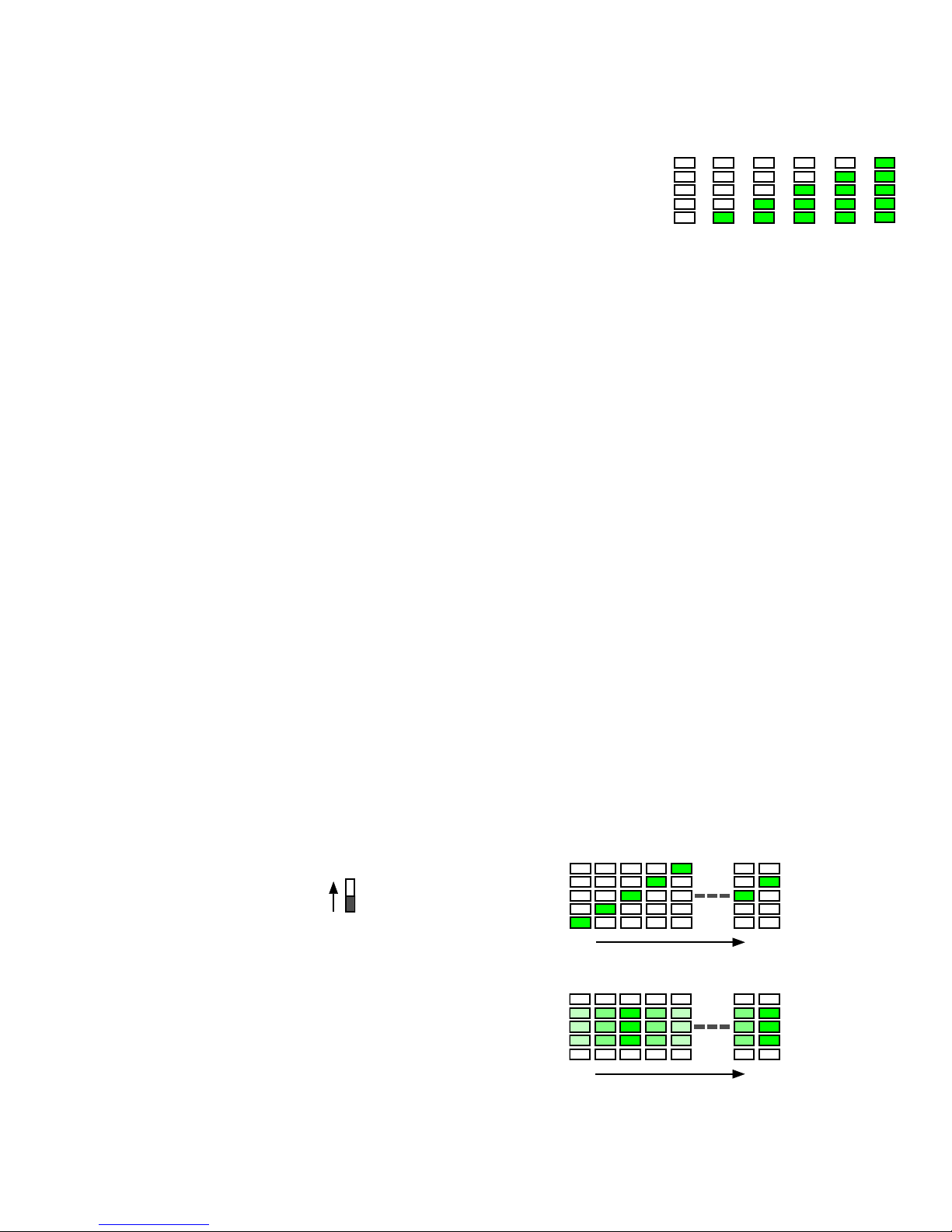
DIP switch 8 controls what the 5 LEDs on the daughter board display. The 5
LEDs can display Signal Strength or Ambient RF Energy. Refer to the diagram
above (on page 25) in order set the unit to display Signal Strength or Ambient RF
Energy.
Signal Strength Meter
When the unit is set to display signal strength, the LEDs will display the signal
strength of the last received transmission from a device with the same network
ID. Refer to the Signal Strength Meter diagram to see how the LEDs behave in
this mode. The signal strength can be used to make the user aware of poor
signal quality and determine a better location to mount the units.
Antenna Select
DIP switch 9 controls the antenna mode of the unit. Refer to the Antenna Select diagram (see page 25) to set the
Antenna Select DIP switch to the appropriate setting. The mode the unit should set to depends on the part number. The
SPX-5631 and SPX-5641 will have the antenna selection set correctly from the factory.
Chip Antenna
The SPX-5631 should be be set to Chip Antenna setting at all times. The SPX-5631 does not include a dipole antenna
and will not function properly if the unit is set to the External Dipole Antenna setting.
External Dipole Antenna
The SPX-5641 should be set to the External Dipole Antenna setting at all times. The SPX-5641 will not be able
communicate over the full 10,000 foot range if the unit is set to the Chip Antenna setting.
Pairing
DIP switch 10 determines if the unit is in Pairing Mode. When DIP switch 10 is on, the unit will enter pairing mode (refer
to Pairing diagram above on page 25). The Central and Remote units will come paired from the factory. After pairing
mode is first entered, the radio will reboot. After one second, the LEDs display a “scanning” sequence (see diagram
below) indicating the radio is “looking” for another radio also in pairing mode.
Ambient RF Energy
When the unit is set to display ambient RF energy, the LEDs will display the ambient RF energy of the selected channel
regardless of network ID. A greater number of illuminated LEDs indicates less ambient RF energy. A lesser number of
LEDs illuminated indicates more ambient RF energy. Detecting the ambient RF energy can be used to find a channel
most suitable for operation.
Put another unit into Pairing Mode to establish a pair. Both units must be
set to the same channel and network ID to be paired. It is recommended
that the two units be near each other when pairing. Once another unit is
detected which is also in Pairing Mode, the LEDs will flicker, pause,
reset, and finally the 3 center LEDs will settle into a dim-to-bright-to-dim
pattern. This indicates pairing is successful. Pairing Mode can now be
switched off on both units for normal operation.
Cypress Suprex® RF Series - Radio Configuration (Continued)
The pairing function does not affect other units that have already been paired and are NOT in Pairing Mode. However, if
more than two units are put into Pairing Mode at the same time, the results will be arbitrary. The first two radios to
discover each other will be paired regardless of distance or signal strength.
 Loading...