

Page 1

!
Operations Manual
Suprex® Reader Extender
SPX-1300
*/5&(3"5*0/40-65*0/4
CYPRESS
Page 2
"
"
"
"
"
"
"
"
"
"
"
"
"
"
"
"
"
"
"
"
"
"
"
"
"
"
"
"
"
"
"
"
"
"
q! `123458r!
"
"
"
"
"
"
"
"
"
"
"
"
"
"
"
"
Electrical and Mechanical Specifications
Physical
SPX-1300 Aluminum Enclosure 3.5" x 2.75" x .75"
Temp
Storage(-55˚C to + 150˚C)"
Operating(-40˚C to +80˚C)
Humidity
95% (non-condensing)
Power
Input
Unreg Input 8 to 16 VDC* @ 200mA Max
Output
+5VDC @100mA
Data I/O"
Voltage Ratings
Interface
Reader 0- 30VDC"
LED - 0 - 30VDC"
Analog 0 - 5 VDC"
*See Notes on following page for temperature and power ratings
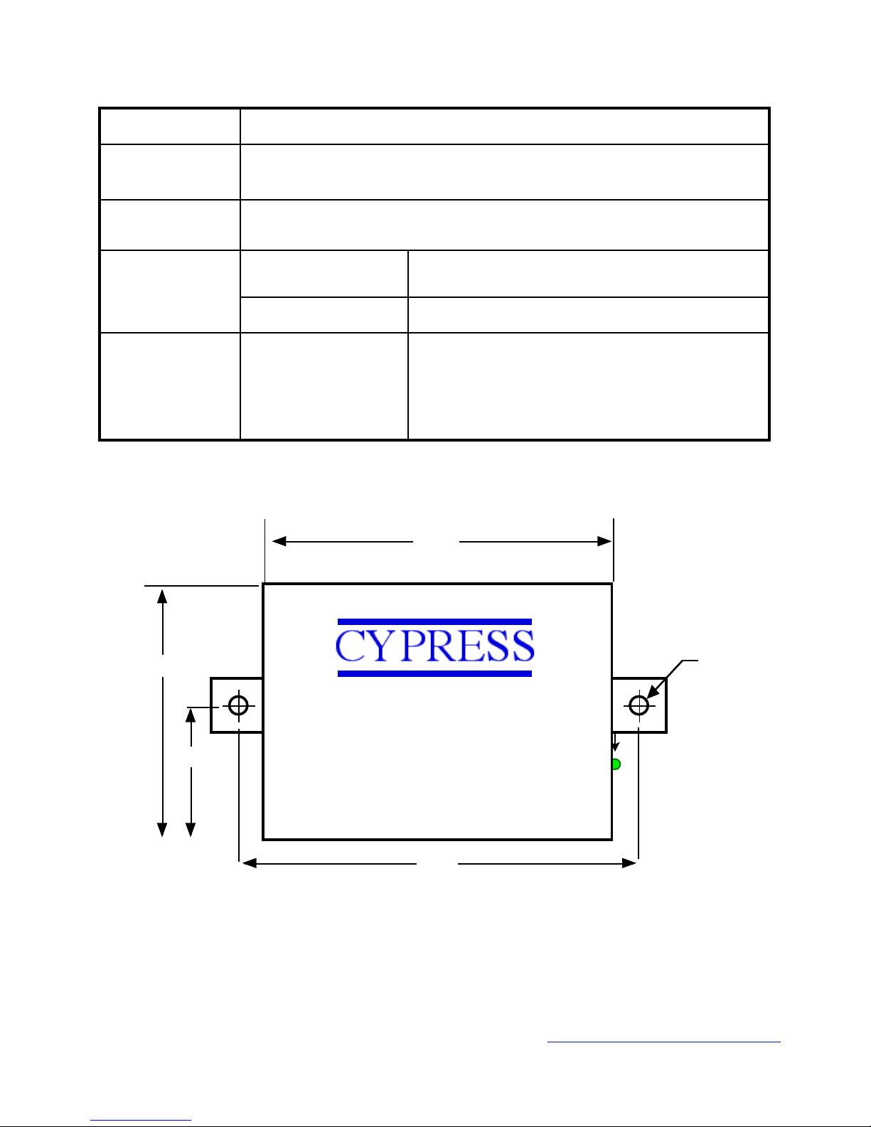
3.3”
DataBender CVX-1300
2.8”
1.4”
3.65”
ø 0.15”
External Dimensions and Mounting Holes
Unit Height = 0.75”
This complies with part 15 of the FCC rules !
Operation is subject to the following two conditions: !
(1) This device may not cause harmful interference, and !
(2) this device must accept any interference received, including
interference that may cause undesired operation.
Cypress Computer Systems, Inc. ⌖ Lapeer, MI 48446 ⌖ www.cypresscomputer.com
© 2012 Cypress Computer Systems Inc.
Page 3

"
"
"
"
"
"
"
"
"
"
"
"
"
"
"
"
"
"
"
"
"
"
"
"
"
"
"
"
"
"
"
"
"
"
"
"
"
"
"
"
"
"
"
"
"
"
"
"
"
"
"
External connections and DIP Switch Settings
8-485(+)"
7-485(-)"
6-+5 VDC Out"
5-Prog Res 2"
4-Prog Res 1"
3-LED Input"
2-D1/Data/F2F Out-"
1-D0/CLK Out
2-8 to 16 VDC In"
1-Ground
Diagnostic LED
12-RLY4 N.O."
11-RLY4 Com"
10-RLY4 N.C."
9-RLY3 N.O."
8-RLY3 Com"
7-RLY3 N.C."
6-RS232 Out"
5-RS232 In"
4-Ground"
3-Aux Out"
2-Relay2 Input"
1-Relay1 Input"
*
Central Unit
2-8 to 16 VDC In"
1-Ground
12-RLY2 N.O."
11-RLY2 Com"
10-RLY2 N.C."
9-RLY1 N.O."
8-RLY1 Com"
7-RLY1 N.C."
6-RS232 Out"
5-RS232 In"
4-Ground"
3-Aux In"
2-N/C"
1-N/C"
8-485(+)"
7-485(-)"
6-+5 VDC Out"
5-RLY4 Input (5V)"
4-RLY3 Input (5V)"
3-LED Output"
2-D1/Data/F2F Input"
1-D0/CLK Input
*
Remote Unit
Note: F/2F connections"
support unsupervised "
mode only.
1234567
8
Switch
6 7 8
0
1 x
2 x
3 x x
4 x
5 x x
6 x x
7 x x x
Wiegand
Wiegand / No Filter
Strobed Rising Edge (MR-5)
Strobed Rising Edge (Dorad0 644)
Strobed Rising (Mag-Tek)
Strobed Falling Edge
Reserved
F2F
x = ON
Dip switch #4 is ON
-Disable Pullup resistors
Dip switch #4 is OFF
-Enable Pullup resistors
DIP Switch #1 ON "
-Service Mode"
DIP Switch #1 OFF"
-Run Mode
Central Unit !
Settings
Switch
6 7 8
0
1 x
2 x
3 x x
4 x
5 x x
6 x x
7 x x x
Wiegand
Wiegand / No Filter
Strobed Rising Edge (MR-5)
Strobed Rising Edge (Dorad0 644)
Strobed Rising (Mag-Tek)
Strobed Falling Edge
Reserved
F2F
x = ON
Remote Unit !
Settings
1234567
8
Dip switch #4 is ON
-Enable Pullup resistors
Dip switch #4 is OFF
-Disable Pullup resistors
DIP Switch #1 ON "
-Service Mode"
DIP Switch #1 OFF"
-Run Mode
Page 4

"
"
"
"
"
"
"
"
"
"
"
"
"
"
"
"
"
"
"
"
"
"
"
"
"
"
"
"
"
"
81012
14
16
805535
-40
Ambient Temperature
(Degrees Celsius)
Supply Voltage
Temperature/Voltage de-rating curve
Electrical and Environmental Specifications
The SPX-1300 units should be operated with a filtered 12 Volt nominal DC supply. "
However, any voltage between 8 and 16 volts can be utilized by following the temperature /voltage derating curve.
Voltage should not exceed 16 VDC."
"
Digital Data (D0/D1) Inputs and Outputs are OpenCollector with switchable 1k pullup resistors.."
"
Data I/O Points are rated for the following voltages:"
0 - 5 VDC with pullups on "
0- 24 VDC with pullups off"
"
All Digital Inputs and Outputs are 0 - 24 VDC tolerant . Pullup resistors should be disabled when using I/O at voltages
greater than 5VDC to prevent excessive current draw and possible component damage. "
"
Analog Inputs are rated for 5 VDC max."
The Relay 3, Relay 4 inputs and Programming resistor inputs are analog inputs and are limited to 5 volts DC Maximum."
"
All inputs and outputs are provided with transient and static protection."
"
The RS-485 communication channel will provide the best performance using shielded twisted pair wiring. Other wire
types can be used, and performance will depend upon actual field conditions. The Suprex units will typically function
with: Coax, THHN building wire, Cat5 and Cat 3 cable, etc.
Page 5

"
"
"
"
"
"
"
"
"
"
"
"
"
"
"
"
"
"
"
"
"
"
"
"
"
"
"
"
"
"
"
"
"
"
"
"
"
"
"
"
"
"
"
"
"
"
"
"
"
"
"
When the Suprex units are operating correctly and have a valid communication channel between"
the Remote and Central units the Diagnostic indicators on each unit will flash green rapidly "
(2-3 flashed per second)."
"
If the units are not communicating, viewing the diagnostic indicator LED’s may help to determine
the "
nature of the problem."
"
DIAGNOSTIC LED NOT ILLUMINATED:"
"
If the LED(s) are not illuminated on the unit(s) then the unit is not getting power. The Diagnostic
LED’s"
will be illuminated when power is applied."
"
CENTRAL UNIT FLASHING BETWEEN RED/GREEN:"
"
With power applied and no communication path between the Remote and Central, the Central
unit will flash the diagnostic indicator alternately between Red and Green."
"
REMOTE UNIT ILLUMINATED RED:"
"
The Remote unit will diagnostic LED will illuminate solid (not flashing) red if it is not receiving
communication from the Central."
"
REMOTE AND CENTRAL UNITS FLASHING BETWEEN RED/GREEN:"
"
The Central is not Receiving communication from the Remote.
Troubleshooting - Diagnostic Indicators
Page 6
"
"
"
"
"
"
"
"
"
"
"
"
"
"
"
"
"
"
"
"
"
"
"
"
"
"
"
"
"
"
"
"
"
"
"
"
"
"
"
"
"
"
"
"
"
"
"
"
"
"
"
*
Suprex Operation and Initial Setup
Actual connections will differ based on the type of format, features utilized, and equipment interface."
The following diagrams are an example of a typical installation using the Suprex 1300 and a Wiegand format
Reader and Access Control Panel."
"
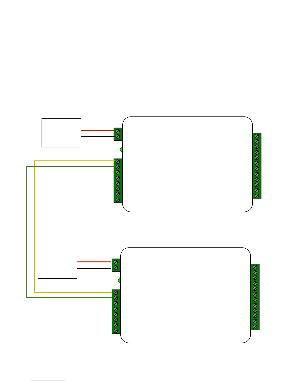
1. First connect units as shown below to verify basic function and communication. This should be done in a
convenient location such as a bench top before installing units in the field. Both units can share the same power
supply if the power supply has sufficient capacity. "
"
"
When Connected as shown below, both units should have the Diagnostic LED flashing Green about 2-3 flashes
per second (Rapid flashing)
Central Unit
*
Remote Unit
2-8 to 16 VDC In"
1-Ground
12-RLY2 N.O."
11-RLY2 Com"
10-RLY2 N.C."
9-RLY1 N.O."
8-RLY1 Com"
7-RLY1 N.C."
6-RS232 Out"
5-RS232 In"
4-Ground"
3-Aux In"
2-N/C"
1-N/C"
8-485(+)"
7-485(-)"
6-+5 VDC Out"
5-RLY4 Input (5V)"
4-RLY3 Input (5V)"
3-LED Output"
2-D1/Data/F2F Input"
1-D0/CLK Input
2-8 to 16 VDC In"
1-Ground
8-485(+)"
7-485(-)"
6-+5 VDC Out"
5-Prog Res 2"
4-Prog Res 1"
3-LED Input"
2-D1/Data/F2F Out"
1-D0/Clock Out"
1-D0/CLK Output
12-RLY4 N.O."
11-RLY4 Com"
10-RLY4 N.C."
9-RLY3 N.O."
8-RLY3 Com"
7-RLY3 N.C."
6-RS232 Out"
5-RS232 In"
4-Ground"
3-Aux Out"
2-Relay2 Input"
1-Relay1 Input"
8 - 16 VDC "
Power "
Supply
Ground (0V)
+VDC
8 - 16 VDC "
Power "
Supply
Ground (0V)
+VDC
Page 7
*
"
"
"
"
"
"
"
"
"
"
"
"
"
"
"
"
"
"
"
"
"
"
"
"
"
"
"
"
"
"
"
"
"
"
"
"
"
"
"
"
"
"
"
"
"
"
"
"
"
"
"
Suprex Operation and Initial Setup
2. Remove power from the units and set DIP switches if necessary. The units are set for Wiegand format data as
the default setting from the factory. If a Wiegand format reader is being used, it should not be necessary to change
the DIP switch setting."
"
For applications that require a change in the DIP switch setting. Remove the board from the enclosure and set the
DIP switch to the required format on both the Central and Remote units."
Refer to DIP switch diagram for the list of available formats."
"
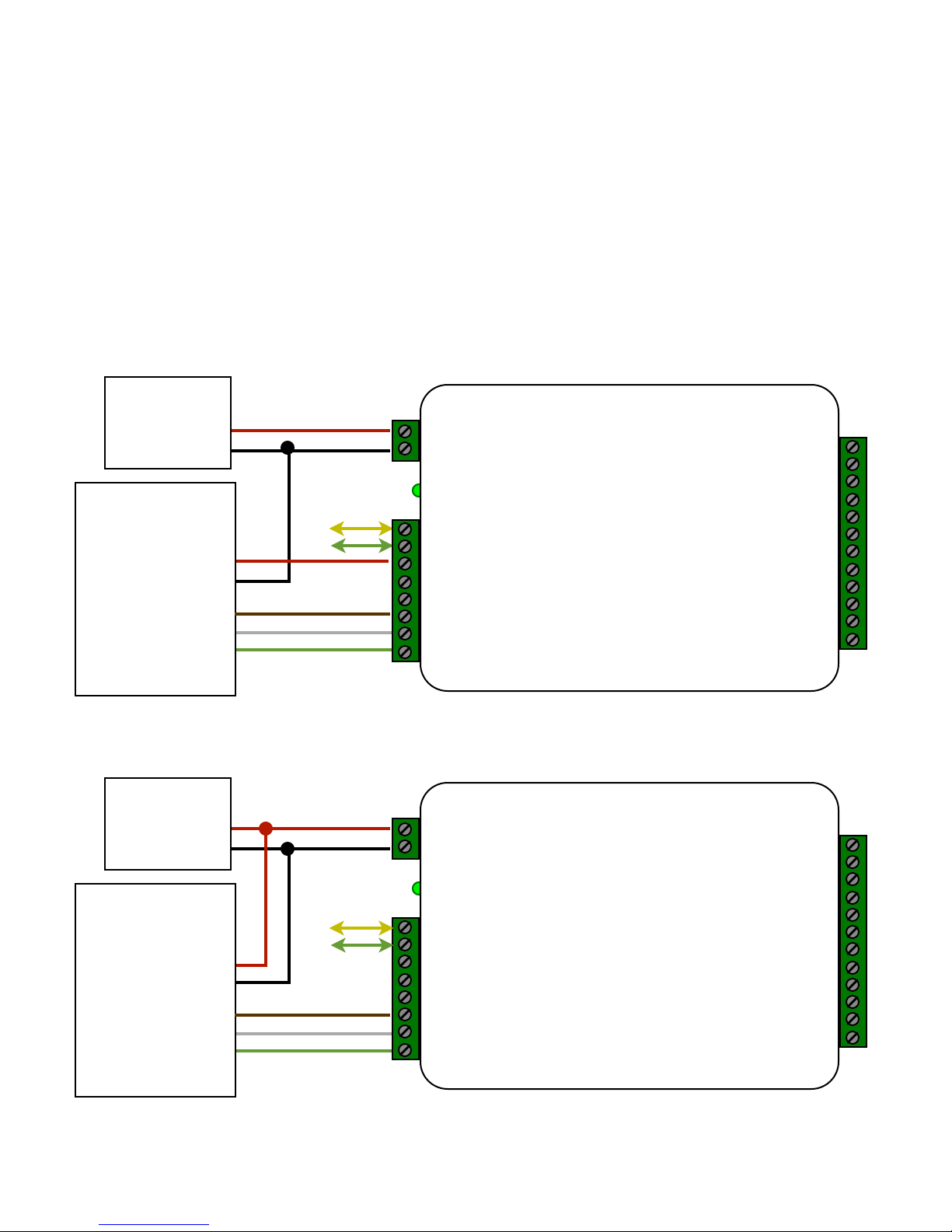
3. Connect the Reader to the Remote unit. 2 different standard applications are shown as examples below."
"
Note: The LED and Door Strike operation of the SPX-1300 differs from previous versions. "
The connection and operation is covered in the next 2 pages.
8 - 16 VDC "
Power "
Supply
"
DC Power In"
Ground"
"
LED In"
Data 1"
Data 0
Wiegand Card "
Reader
Remote Unit
2-8 to 16 VDC In"
1-Ground
12-RLY2 N.O."
11-RLY2 Com"
10-RLY2 N.C."
9-RLY1 N.O."
8-RLY1 Com"
7-RLY1 N.C."
6-RS232 Out"
5-RS232 In"
4-Ground"
3-Aux In"
2-N/C"
1-N/C"
8-485(+)"
7-485(-)"
6-+5 VDC Out"
5-RLY4 Input (5V)"
4-RLY3 Input (5V)"
3-LED Output"
2-D1/Data/F2F Input"
1-D0/CLK Input
485 to "
Central
Wiegand Reader with 8-16 Volt power Connections
485 to "
Central
Wiegand Reader with 5 Volt power supplied by Suprex
8 - 16 VDC "
Power "
Supply
"
DC Power In"
Ground"
"
LED In"
Data 1"
Data 0
Wiegand Card "
Reader
*
Remote Unit
2-8 to 16 VDC In"
1-Ground
12-RLY2 N.O."
11-RLY2 Com"
10-RLY2 N.C."
9-RLY1 N.O."
8-RLY1 Com"
7-RLY1 N.C."
6-RS232 Out"
5-RS232 In"
4-Ground"
3-Aux In"
2-N/C"
1-N/C"
8-485(+)"
7-485(-)"
6-+5 VDC Out"
5-RLY4 Input (5V)"
4-RLY3 Input (5V)"
3-LED Output"
2-D1/Data/F2F Input"
1-D0/CLK Input
Format setup and Remote Side Basic Reader Connections
Page 8
*
"
"
"
"
"
"
"
"
"
"
"
"
"
"
"
"
"
"
"
"
"
"
"
"
"
"
"
"
"
"
"
"
"
"
"
"
"
"
"
"
"
"
"
"
"
"
"
"
"
"
"
*
Suprex Operation and Initial Setup
Central Side Basic Panel Connections
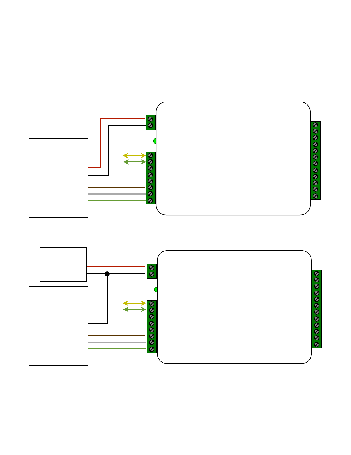
4. Connect the Central unit to the Access control panel. Power can be supplied by either the Access "
Control Panel or an External Power supply. A ground connection must be provided to the Suprex unit in either case.
485 to "
Central
485 to "
Central
8 - 16 VDC "
Power "
Supply
"
"
Ground"
"
LED In"
Data 1"
Data 0
Wiegand "
Access Control
Wiegand Format Access Control Panel with 8-16 Volt Power From Panel
"
DC Power"
Ground"
"
LED In"
Data 1"
Data 0
Wiegand "
Access Control
Central Unit
2-8 to 16 VDC In"
1-Ground
8-485(+)"
7-485(-)"
6-+5 VDC Out"
5-Prog Res 2"
4-Prog Res 1"
3-LED Input"
2-D1/Data/F2F Out "
1-D0/Clock Out"
1-D0/CLK Output
12-RLY4 N.O."
11-RLY4 Com"
10-RLY4 N.C."
9-RLY3 N.O."
8-RLY3 Com"
7-RLY3 N.C."
6-RS232 Out"
5-RS232 In"
4-Ground"
3-Aux Out"
2-Relay2 Input"
1-Relay1 Input"
Central Unit
2-8 to 16 VDC In"
1-Ground
8-485(+)"
7-485(-)"
6-+5 VDC Out"
5-Prog Res 2"
4-Prog Res 1"
3-LED Input"
2-D1/Data/F2F Out "
1-D0/Clock Out"
1-D0/CLK Output
12-RLY4 N.O."
11-RLY4 Com"
10-RLY4 N.C."
9-RLY3 N.O."
8-RLY3 Com"
7-RLY3 N.C."
6-RS232 Out"
5-RS232 In"
4-Ground"
3-Aux Out"
2-Relay2 Input"
1-Relay1 Input"
Wiegand Format Access Control Panel with 8-16 Volt Power From External Supply
Page 9
"
"
"
"
"
"
"
"
"
"
"
"
"
"
"
"
"
"
"
"
"
"
"
"
"
"
"
"
"
"
"
"
"
"
"
"
"
"
"
"
"
"
"
"
"
"
"
"
"
"
"
Suprex Operation and Initial Setup
Central Side Basic Panel Connections
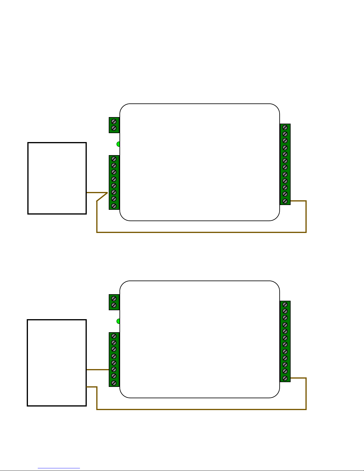
5. To activate the relay on the Remote unit connect as shown below. These connections can be used to allow the
Remote relay to operate a DOOR STRIKE, GATE, or other locking hardware. Refer to following pages in this
document for details of each I/O operation and connection. The Relay inputs are active LOW and will activate the
relay when connected to ground."
"
There are two relays available for accessory outputs at the Remote end. Either relay can be used to provide the Door
Strike or Gate activation function. This example uses Relay 1.
*
Central Unit
2-8 to 16 VDC In"
1-Ground
8-485(+)"
7-485(-)"
6-+5 VDC Out"
5-Prog Res 2"
4-Prog Res 1"
3-LED Input"
2-D1/Data/F2F Out "
1-D0/Clock Out"
1-D0/CLK Output
12-RLY4 N.O."
11-RLY4 Com"
10-RLY4 N.C."
9-RLY3 N.O."
8-RLY3 Com"
7-RLY3 N.C."
6-RS232 Out"
5-RS232 In"
4-Ground"
3-Aux Out"
2-Relay2 Input"
1-Relay1 Input"
Access Control !
Panel
LED OUT
Typical Access Control Panel Connection to activate Door Strike and reader LED.
Strike follows LED
Only Relay and LED Connections are shown for clarity, refer to previous diagrams for
Power,Data and communications connections.
*
Central Unit
2-8 to 16 VDC In"
1-Ground
8-485(+)"
7-485(-)"
6-+5 VDC Out"
5-Prog Res 2"
4-Prog Res 1"
3-LED Input"
2-D1/Data/F2F Out "
1-D0/Clock Out"
1-D0/CLK Output
12-RLY4 N.O."
11-RLY4 Com"
10-RLY4 N.C."
9-RLY3 N.O."
8-RLY3 Com"
7-RLY3 N.C."
6-RS232 Out"
5-RS232 In"
4-Ground"
3-Aux Out"
2-Relay2 Input"
1-Relay1 Input"
Access Control !
Panel
LED OUT"
"
STRIKE
Typical Access Control Panel Connection to activate Door Strike and reader LED. Strike
follows separate panel output.
Page 10
*
*
Remote Unit
"
"
"
"
"
"
"
"
"
"
"
"
"
"
"
"
"
"
"
"
"
"
"
"
"
"
"
"
"
"
"
"
"
"
"
"
"
"
"
"
"
"
"
"
"
"
"
"
"
"
"
Suprex Operation and Initial Setup
I/O Controls
Central Unit
2-8 to 16 VDC In"
1-Ground
8-485(+)"
7-485(-)"
6-+5 VDC Out"
5-Prog Res 2"
4-Prog Res 1"
3-LED Input"
2-D1/Data/F2F Out "
1-D0/Clock Out"
1-D0/CLK Output
12-RLY4 N.O."
11-RLY4 Com"
10-RLY4 N.C."
9-RLY3 N.O."
8-RLY3 Com"
7-RLY3 N.C."
6-RS232 Out"
5-RS232 In"
4-Ground"
3-Aux Out"
2-Relay2 Input"
1-Relay1 Input"
2-8 to 16 VDC In"
1-Ground
12-RLY2 N.O."
11-RLY2 Com"
10-RLY2 N.C."
9-RLY1 N.O."
8-RLY1 Com"
7-RLY1 N.C."
6-RS232 Out"
5-RS232 In"
4-Ground"
3-Aux In"
2-N/C"
1-N/C"
8-485(+)"
7-485(-)"
6-+5 VDC Out"
5-RLY4 Input (5V)"
4-RLY3 Input (5V)"
3-LED Output"
2-D1/Data/F2F Input"
1-D0/CLK Input
Input
Red arrow denotes direction!
of command signal
Output
LED Input and Output
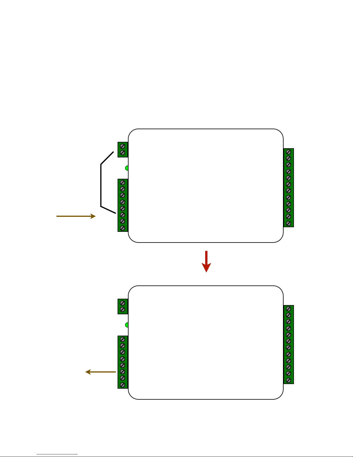
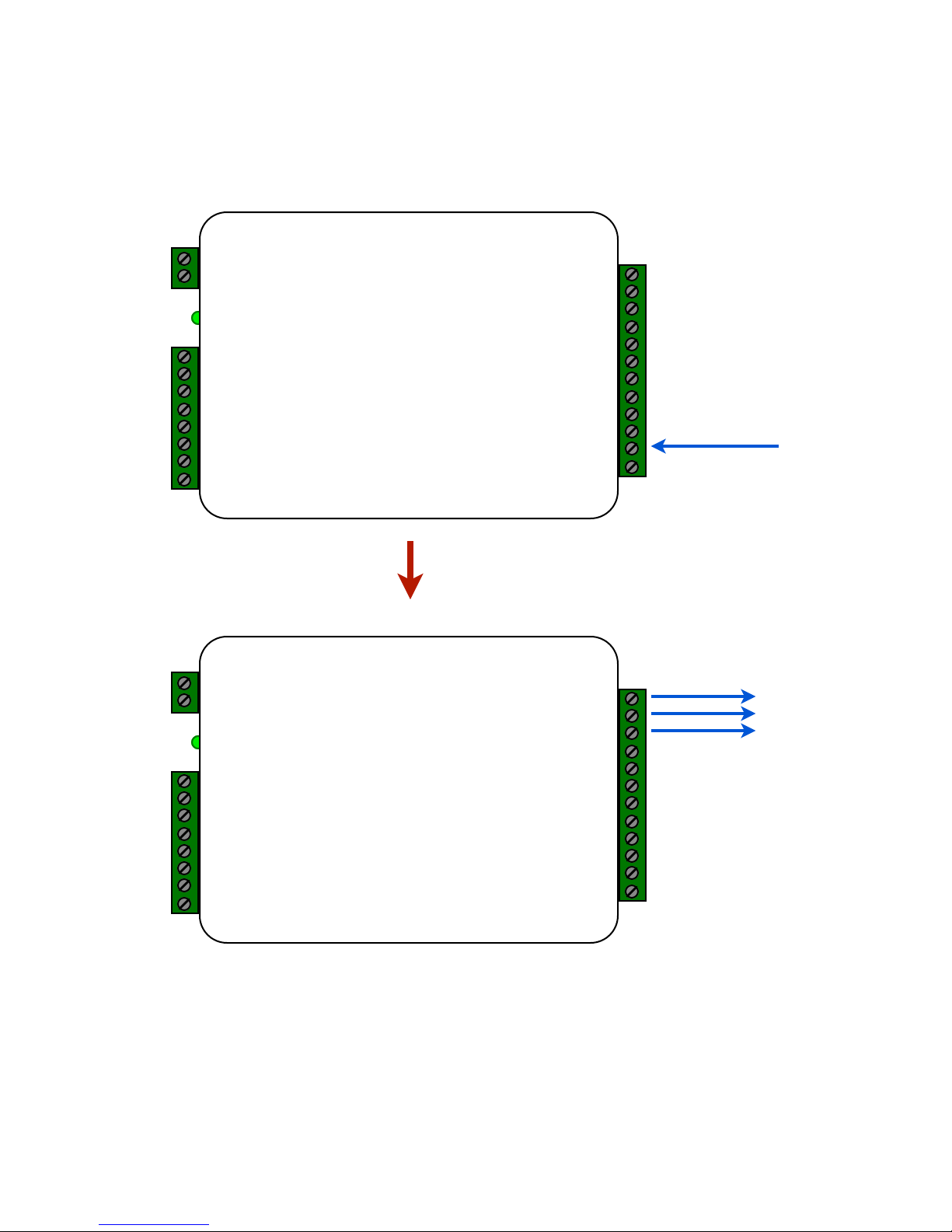
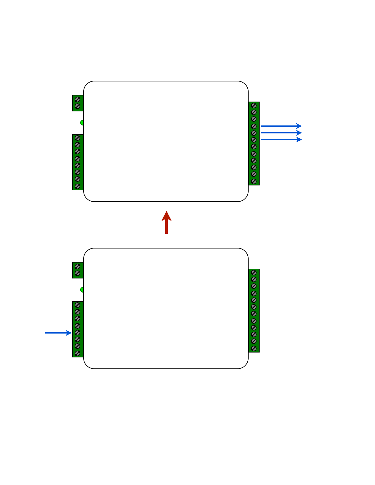
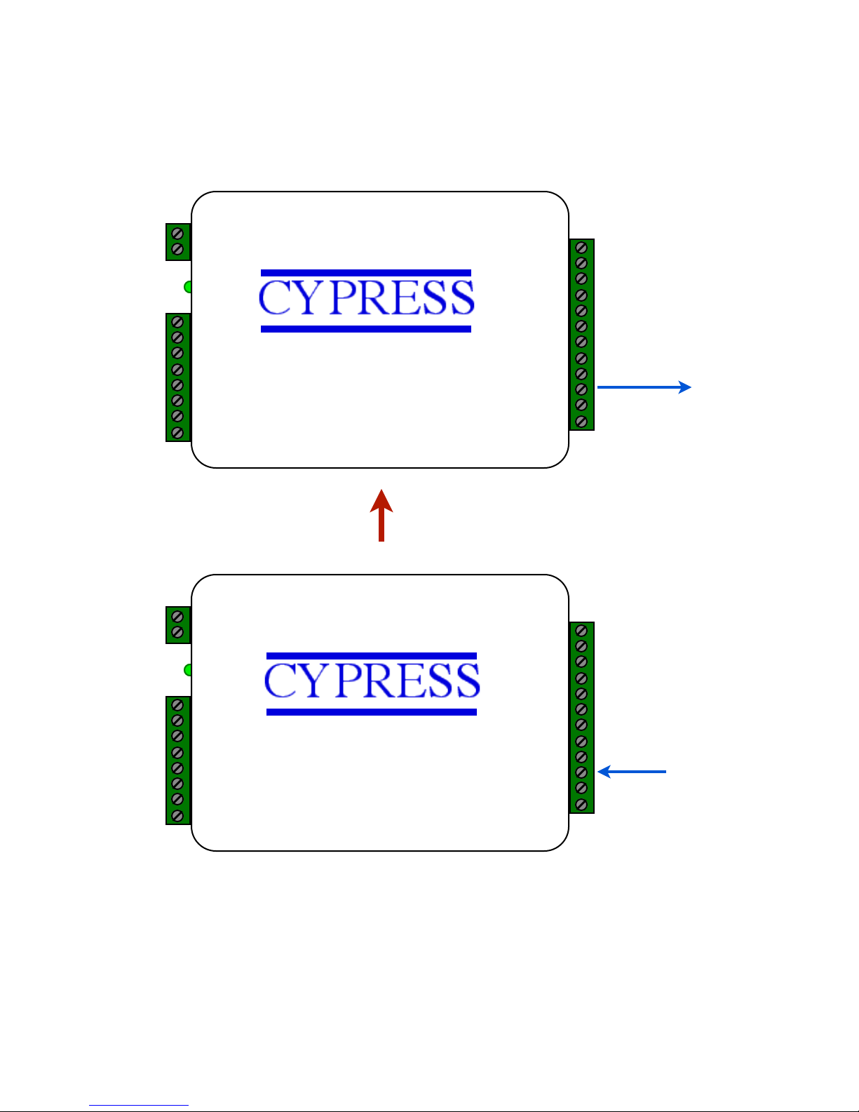
6. The Cypress SPX-1300 provides additional data channels to support access control hardware such as door
strikes, tamper alarms, request to exit status, etc. These signals are sent to and from the Remote and Central units
without the need to run additional wiring."
"
The accessory control I/O use active low inputs. When the inputs are floating (nothing connected) the associated
output will be set to a high level. When the input is set to 0Volts (Ground) the input will activate its associated
output. All Accessory outputs are Open Collector type and will switch to Ground when activated."
"
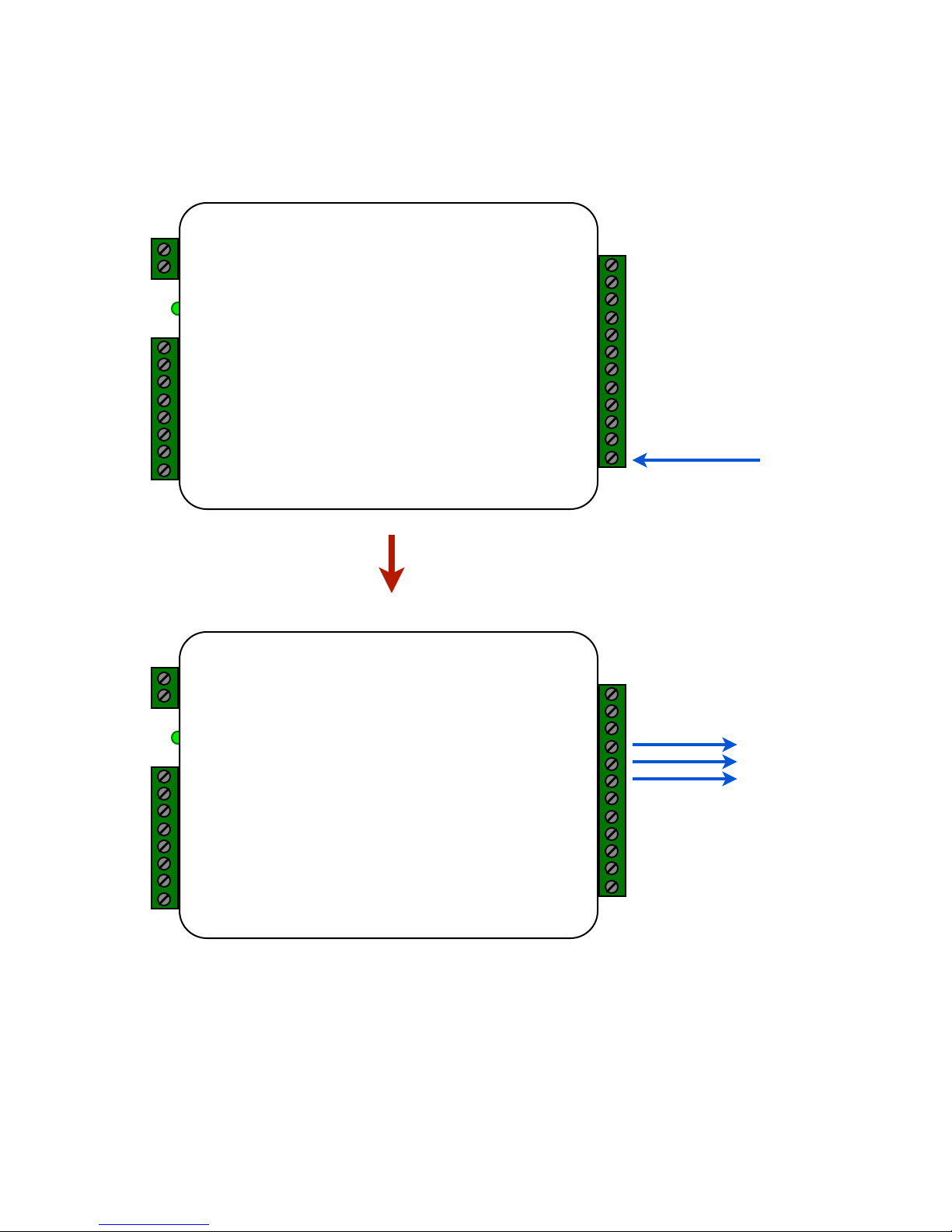
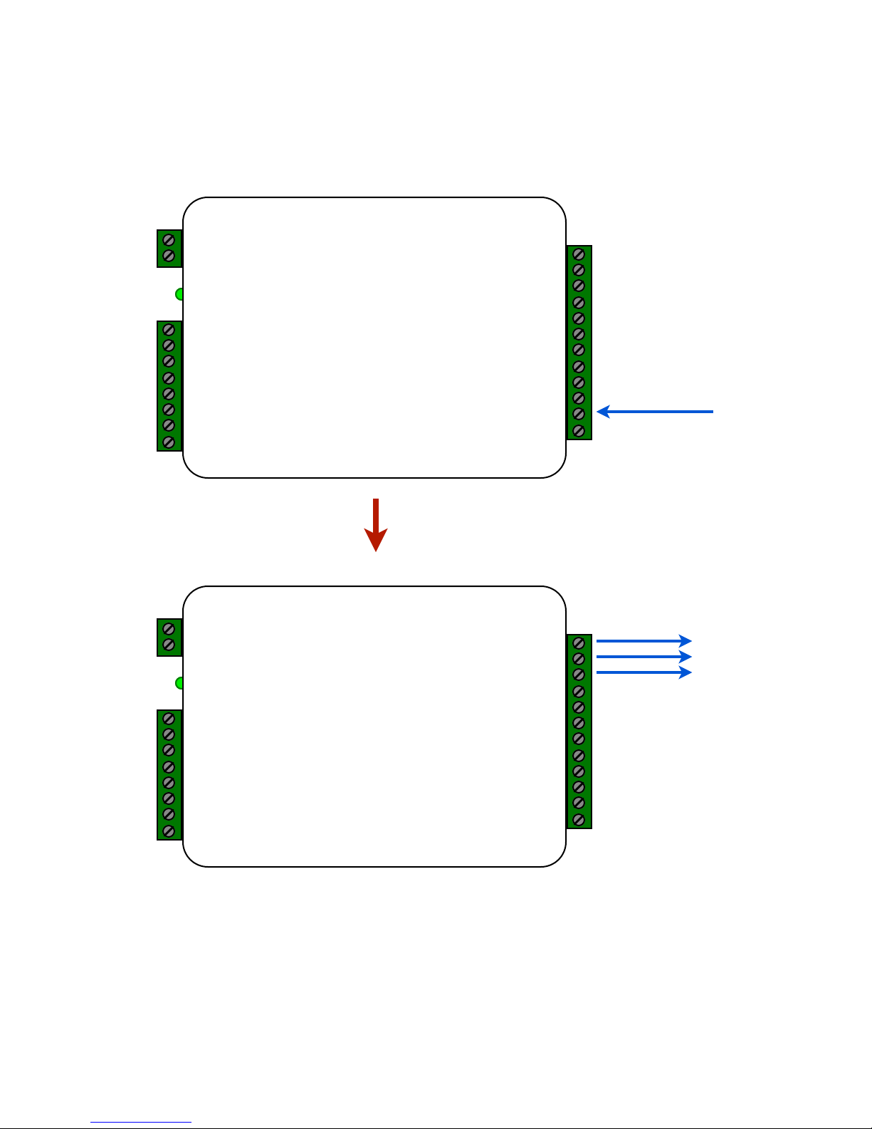
Each input will have an associated output. See the following pages for a diagram of each I/O pair."
Inputs can be tested by making a jumper connection to ground and monitoring the associated output.
Page 11
"
"
"
"
"
"
"
"
"
"
"
"
"
"
"
"
"
"
"
"
"
"
"
"
"
"
"
"
"
"
"
"
"
"
"
"
"
"
"
"
"
"
"
"
"
"
"
"
"
"
"
Suprex Operation and Initial Setup
I/O Controls
*
Central Unit
2-8 to 16 VDC In"
1-Ground
8-485(+)"
7-485(-)"
6-+5 VDC Out"
5-Prog Res 2"
4-Prog Res 1"
3-LED Input"
2-D1/Data/F2F Out "
1-D0/Clock Out"
1-D0/CLK Output
12-RLY4 N.O."
11-RLY4 Com"
10-RLY4 N.C."
9-RLY3 N.O."
8-RLY3 Com"
7-RLY3 N.C."
6-RS232 Out"
5-RS232 In"
4-Ground"
3-Aux Out"
2-Relay2 Input"
1-Relay1 Input"
*
Remote Unit
2-8 to 16 VDC In"
1-Ground
12-RLY2 N.O."
11-RLY2 Com"
10-RLY2 N.C."
9-RLY1 N.O."
8-RLY1 Com"
7-RLY1 N.C."
6-RS232 Out"
5-RS232 In"
4-Ground"
3-Aux In"
2-N/C"
1-N/C"
8-485(+)"
7-485(-)"
6-+5 VDC Out"
5-RLY4 Input (5V)"
4-RLY3 Input (5V)"
3-LED Output"
2-D1/Data/F2F Input"
1-D0/CLK Input
Input
Red arrow denotes direction!
of command signal
Output
Relay 1 Input and Output
Page 12
"
"
"
"
"
"
"
"
"
"
"
"
"
"
"
"
"
"
"
"
"
"
"
"
"
"
"
"
"
"
"
"
"
"
"
"
"
"
"
"
"
"
"
"
"
"
"
"
"
"
"
*
Central Unit
2-8 to 16 VDC In"
1-Ground
8-485(+)"
7-485(-)"
6-+5 VDC Out"
5-Prog Res 2"
4-Prog Res 1"
3-LED Input"
2-D1/Data/F2F Out "
1-D0/Clock Out"
1-D0/CLK Output
12-RLY4 N.O."
11-RLY4 Com"
10-RLY4 N.C."
9-RLY3 N.O."
8-RLY3 Com"
7-RLY3 N.C."
6-RS232 Out"
5-RS232 In"
4-Ground"
3-Aux Out"
2-Relay2 Input"
1-Relay1 Input"
*
Remote Unit
2-8 to 16 VDC In"
1-Ground
12-RLY2 N.O."
11-RLY2 Com"
10-RLY2 N.C."
9-RLY1 N.O."
8-RLY1 Com"
7-RLY1 N.C."
6-RS232 Out"
5-RS232 In"
4-Ground"
3-Aux In"
2-N/C"
1-N/C"
8-485(+)"
7-485(-)"
6-+5 VDC Out"
5-RLY4 Input (5V)"
4-RLY3 Input (5V)"
3-LED Output"
2-D1/Data/F2F Input"
1-D0/CLK Input
Input
Red arrow denotes direction!
of command signal
Relay 2 Input and Output
Output
Suprex Operation and Initial Setup
I/O Controls
Page 13
"
"
"
"
"
"
"
"
"
"
"
"
"
"
"
"
"
"
"
"
"
"
"
"
"
"
"
"
"
"
"
"
"
"
"
"
"
"
"
"
"
"
"
"
"
"
"
"
"
"
"
*
Central Unit
2-8 to 16 VDC In"
1-Ground
8-485(+)"
7-485(-)"
6-+5 VDC Out"
5-Prog Res 2"
4-Prog Res 1"
3-LED Input"
2-D1/Data/F2F Out "
1-D0/Clock Out"
1-D0/CLK Output
12-RLY4 N.O."
11-RLY4 Com"
10-RLY4 N.C."
9-RLY3 N.O."
8-RLY3 Com"
7-RLY3 N.C."
6-RS232 Out"
5-RS232 In"
4-Ground"
3-Aux Out"
2-Relay2 Input"
1-Relay1 Input"
*
Remote Unit
2-8 to 16 VDC In"
1-Ground
12-RLY2 N.O."
11-RLY2 Com"
10-RLY2 N.C."
9-RLY1 N.O."
8-RLY1 Com"
7-RLY1 N.C."
6-RS232 Out"
5-RS232 In"
4-Ground"
3-Aux In"
2-N/C"
1-N/C"
8-485(+)"
7-485(-)"
6-+5 VDC Out"
5-RLY4 Input (5V)"
4-RLY3 Input (5V)"
3-LED Output"
2-D1/Data/F2F Input"
1-D0/CLK Input
Input
Red arrow denotes direction!
of command signal
Relay 2 Input and Output
Output
Suprex Operation and Initial Setup
I/O Controls
Page 14
"
"
"
"
"
"
"
"
"
"
"
"
"
"
"
"
"
"
"
"
"
"
"
"
"
"
"
"
"
"
"
"
"
"
"
"
"
"
"
"
"
"
"
"
"
"
"
"
"
"
"
*
Central Unit
2-8 to 16 VDC In"
1-Ground
8-485(+)"
7-485(-)"
6-+5 VDC Out"
5-Prog Res 2"
4-Prog Res 1"
3-LED Input"
2-D1/Data/F2F Out "
1-D0/Clock Out"
1-D0/CLK Output
12-RLY4 N.O."
11-RLY4 Com"
10-RLY4 N.C."
9-RLY3 N.O."
8-RLY3 Com"
7-RLY3 N.C."
6-RS232 Out"
5-RS232 In"
4-Ground"
3-Aux Out"
2-Relay2 Input"
1-Relay1 Input"
*
Remote Unit
2-8 to 16 VDC In"
1-Ground
12-RLY2 N.O."
11-RLY2 Com"
10-RLY2 N.C."
9-RLY1 N.O."
8-RLY1 Com"
7-RLY1 N.C."
6-RS232 Out"
5-RS232 In"
4-Ground"
3-Aux In"
2-N/C"
1-N/C"
8-485(+)"
7-485(-)"
6-+5 VDC Out"
5-RLY4 Input (5V)"
4-RLY3 Input (5V)"
3-LED Output"
2-D1/Data/F2F Input"
1-D0/CLK Input
Input
Red arrow denotes direction!
of command signal
Relay 3 Input and Output
Output
Suprex Operation and Initial Setup
I/O Controls
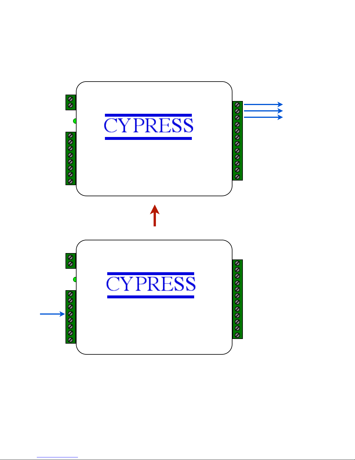
Relay 3 functions as an Alarm relay and monitors the condition of the communication link between the
Central and Remote units. Relay 3 is activated when power is applied and the communication link
between the Central and Remote is functioning. Relay 3 will become deactivated (Alarm condition)"
when either the Relay 3 input on the remote is active OR the Remote unit is unable to communicate
with the Central unit.
Page 15
"
"
"
"
"
"
"
"
"
"
"
"
"
"
"
"
"
"
"
"
"
"
"
"
"
"
"
"
"
"
"
"
"
"
"
"
"
"
"
"
"
"
"
"
"
"
"
"
"
"
"
Input
*
Central Unit
2-8 to 16 VDC In"
1-Ground
8-485(+)"
7-485(-)"
6-+5 VDC Out"
5-Prog Res 2"
4-Prog Res 1"
3-LED Input"
2-D1/Data/F2F Out "
1-D0/Clock Out"
1-D0/CLK Output
12-RLY4 N.O."
11-RLY4 Com"
10-RLY4 N.C."
9-RLY3 N.O."
8-RLY3 Com"
7-RLY3 N.C."
6-RS232 Out"
5-RS232 In"
4-Ground"
3-Aux Out"
2-Relay2 Input"
1-Relay1 Input"
*
Remote Unit
2-8 to 16 VDC In"
1-Ground
12-RLY2 N.O."
11-RLY2 Com"
10-RLY2 N.C."
9-RLY1 N.O."
8-RLY1 Com"
7-RLY1 N.C."
6-RS232 Out"
5-RS232 In"
4-Ground"
3-Aux In"
2-N/C"
1-N/C"
8-485(+)"
7-485(-)"
6-+5 VDC Out"
5-RLY4 Input (5V)"
4-RLY3 Input (5V)"
3-LED Output"
2-D1/Data/F2F Input"
1-D0/CLK Input
Red arrow denotes direction!
of command signal
Relay 4 Input and Output
Output
Suprex Operation and Initial Setup
I/O Controls
Page 16
"
"
"
"
"
"
"
"
"
"
"
"
"
"
"
"
"
"
"
"
"
"
"
"
"
"
"
"
"
"
"
"
"
"
"
"
"
"
"
"
"
"
"
*
Central Unit
2-8 to 16 VDC In"
1-Ground
8-485(+)"
7-485(-)"
6-+5 VDC Out"
5-Prog Res 2"
4-Prog Res 1"
3-LED Input"
2-D1/Data/F2F Out "
1-D0/Clock Out"
1-D0/CLK Output
12-RLY4 N.O."
11-RLY4 Com"
10-RLY4 N.C."
9-RLY3 N.O."
8-RLY3 Com"
7-RLY3 N.C."
6-RS232 Out"
5-RS232 In"
4-Ground"
3-Aux Out"
2-Relay2 Input"
1-Relay1 Input"
*
Remote Unit
2-8 to 16 VDC In"
1-Ground
12-RLY2 N.O."
11-RLY2 Com"
10-RLY2 N.C."
9-RLY1 N.O."
8-RLY1 Com"
7-RLY1 N.C."
6-RS232 Out"
5-RS232 In"
4-Ground"
3-Aux In"
2-N/C"
1-N/C"
8-485(+)"
7-485(-)"
6-+5 VDC Out"
5-RLY4 Input (5V)"
4-RLY3 Input (5V)"
3-LED Output"
2-D1/Data/F2F Input"
1-D0/CLK Input
Input
Red arrow denotes direction!
of command signal
Aux Input and Output
Output
Suprex Operation and Initial Setup
I/O Controls
 Loading...