

Page 1
VERTICALDEFLECTION BOOSTER
.
POWERAMPLIFIER
.
FLYBACKGENERATOR
.
THERMALPROTECTION
.
OUTPUTCURRENTUP TO2.0A
.
FLYBACKVOLTAGEUPTO 90V (on Pin5)
.
SUITABLEFORDCCOUPLINGAPPLICATION
DESCRIPTION
Designedfor monitorsand high performanceTVs,
the STV9379 vertical deflection booster delivers
flybackvoltages close to 90V.
TheSTV9379operateswith suppliesup to 42Vand
provides up to 2A
yoke.
TheSTV9379 is offered in HEPTAWATTpackage.
output current to drive the
PP
PP
HEPTAWATT
(PlasticPackage)
ORDER CODE :
STV9379
STV9379
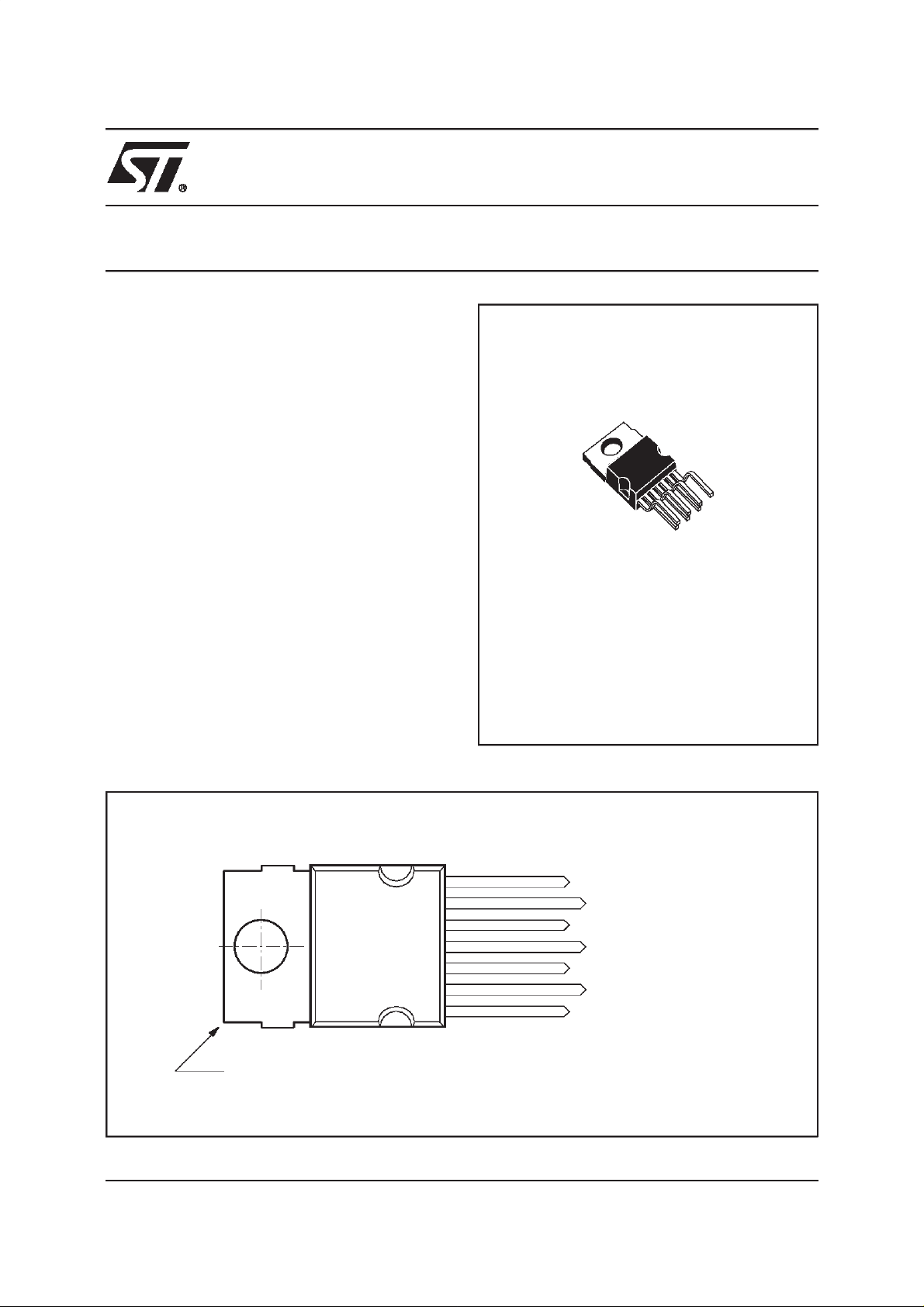
PIN CONNECTIONS
Tab connectedto pin 4
August 1998
7
6
5
4
3
2
1
Non-invertingInput
Output Stage Supply
Output
GND
Flyback Generator
Supply Voltage
InvertingInput
9379-01.EPS
1/5
Page 2
STV9379
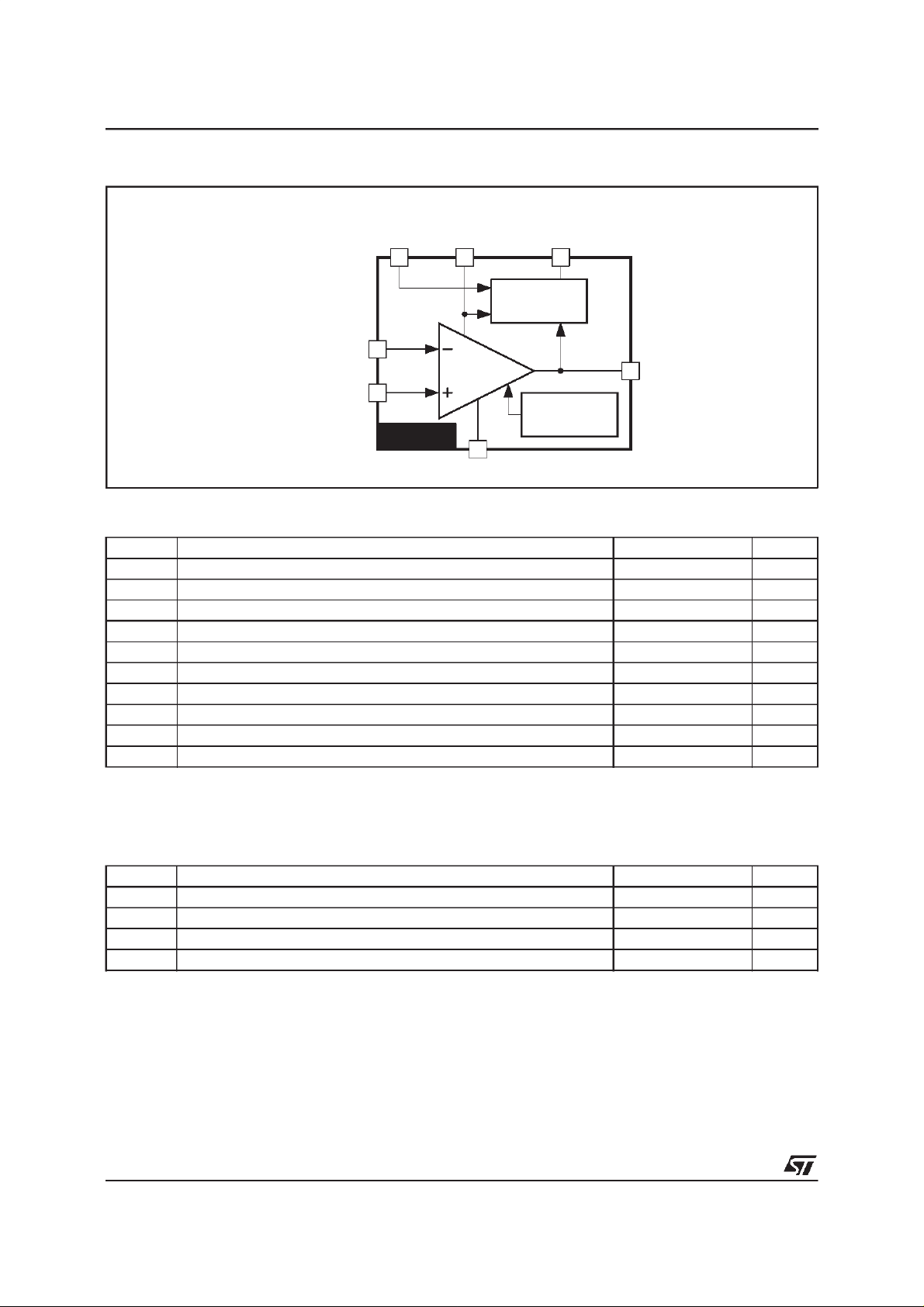
BLOCKDIAGRAM
OUTPUT
SUPPLY
VOLTAGE
236
STAGE
SUPPLY
FLYBACK
GENERATOR
FLYBACK
GENERATOR
INVERTING INPUT
NON-INVERTING INPUT
1
7
POWER
AMPLIFIER
5
OUTPUT
THERMAL
PROTECTION
STV9379
GROUND OR NEGATIVE SUPPLY
4
ABSOLUTE MAXIMUMRATINGS
Symbol Parameter Value Unit
V
V
V
1,V7
I
I
I
V
ESD
T
oper
T
T
Notes : 1. Versus Pin 4.
Supply Voltage (Pin 2) (see note 1) 50 V
S
Flyback Peak Voltage (Pin 6) (see note 1) 100 V
6
Amplifier Input Voltage (Pins 1-7) (see note 1) -0.3, + V
Maximum Output Peak Current (see notes 2 and 3) 1.5 A
O
Maximum Sink Current (first part of flyback) (t < 1ms) 1.5 A
3
Maximum Source Current(t < 1ms) 1.5 A
3
ESD susceptibility: EIAJ Norm (200pF discharged through 0Ω) 300 V
Operating Ambient Temperature - 20, + 75
Storage Temperature - 40, + 150
stg
Junction Temperature +150
j
2. The outputcurrent can reach4A peak for t ≤ 10µs(up to 120Hz).
3. Provided SOAR is respected (see Figures1 and 2).
S
9379-02.EPS
V
o
C
o
C
o
C
9379-01.TBL
THERMAL DATA
Symbol Parameter Value Unit
Junction-case Thermal Resistance Max. 3
Temperature for Thermal Shutdown 150
t
Hysteresis on T
t
Recommended Max. Junction Temperature 120
jr
t
10
2/5
R
th(j-c)
T
∆T
T
o
C/W
o
o
o
C
C
C
9379-02.TBL
Page 3
STV9379
ELECTRICAL CHARACTERISTICS
(V
= 42V,TA=25oC, unlessotherwise specified)
S
Symbol Parameter Test Conditions Min. Typ. Max. Unit
V
I
I
I
I
I
V
∆V
IO
GV VoltageGain 80 dB
V
V
V
D5 - 6
V
D3 - 2
V
V
3SH
Operating Supply Voltage Range VersusPin 4 10 42 V
S
Pin 2 Quiescent Current I3=0,I5= 0 10 20 mA
2
Pin 6 Quiescent Current I3=0,I5=0 5 10 30 mA
6
Max. PeakOutput Current 1 A
O
Amplifier Bias Current V1= 25V,V7= 26V - 0.15 - 1 µA
1
Amplifier Bias Current V1= 26V,V7= 25V - 0.15 - 1 µA
7
Offset Voltage 7mV
IO
/dt Offset Driftversus Temperature - 10 µV/oC
Output Saturation Voltage to GND (Pin 4) I5= 1A 1 1.5 V
5L
Output Saturation Voltage to Supply (Pin 6) I5= - 1A 1.6 2.1 V
5H
Diode Forward Voltage between Pins 5-6 I5= 1A 1.5 2 V
Diode Forward Voltage between Pins 3-2 I3= 1A 1.5 2 V
Saturation Voltage on Pin3 I3= 20mA 0.8 1.2 V
3L
Saturation Voltage to Pin2 (2nd part of flyback) I3= - 1A 2.1 2.9 V
9379-03.TBL
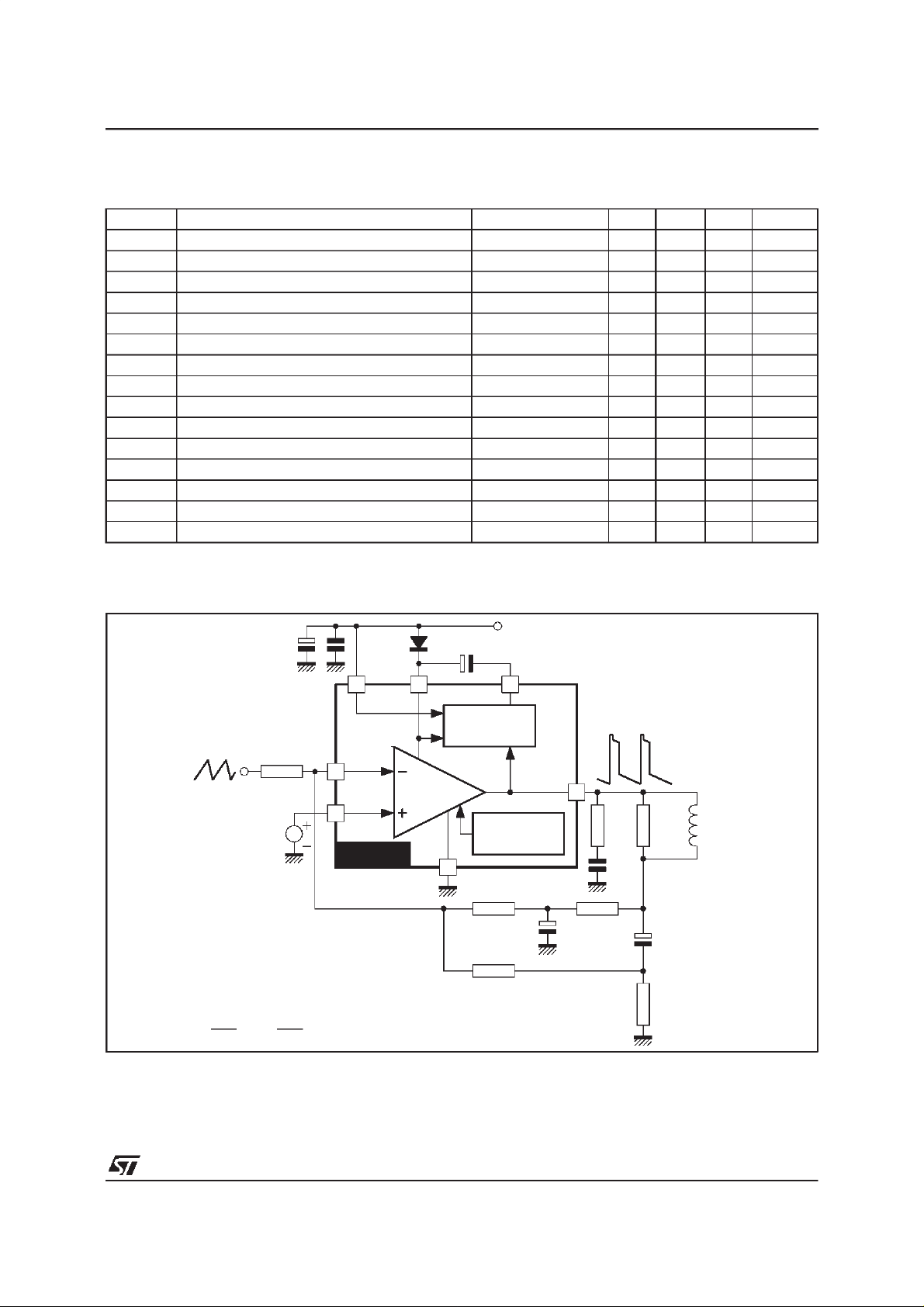
APPLICATIONCIRCUITS
AC COUPLING
V
REF
Ly
<Rd<
(*)
50
µs
R5
Ly
20µs
26
1
7
POWER
AMPLIFIER
STV9379
C
F
FLYBACK
GENERATOR
THERMAL
PROTECTION
4
R3
R2
+V
3
S
5
R4
Rd (*)
1.5Ω
0.22µF
C
R1
Ly
Yoke
L
9379-03.EPS
3/5
Page 4
STV9379
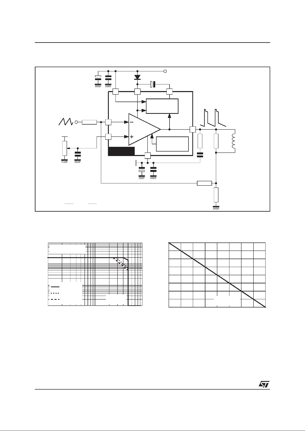
APPLICATIONCIRCUITS (continued)
DC COUPLING
+V
C
F
S
Figure1 :
I(A)
C
10
@T
R5
1
+
V
REF
Vertical
Position
Adjustment
7
STV9379
(*)
50
Ly
µs
<Rd<
Ly
20µs
OutputTransistorsSOA
(for secondarybreakdown)
=25°C
case
26
FLYBACK
GENERATOR
POWER
AMPLIFIER
4
-V
EE
3
THERMAL
PROTECTION
Figure2 :
ISB (%)
100
5
Ly
Yoke
R2
Rd (*)
1.5Ω
0.22µF
R1
SecondaryBreakdownTemperature
Derating Curve
(ISB = secondarybreakdown current)
9379-04.EPS
1
-1
10
t = 1ms
t = 10ms
-2
10
11010
t= 100ms
V(V)
CE
2
9379-05.EPS
4/5
90
80
70
T
(°C)
case
60
25 50 75 100 125
9379-06.EPS
Page 5
STV9379
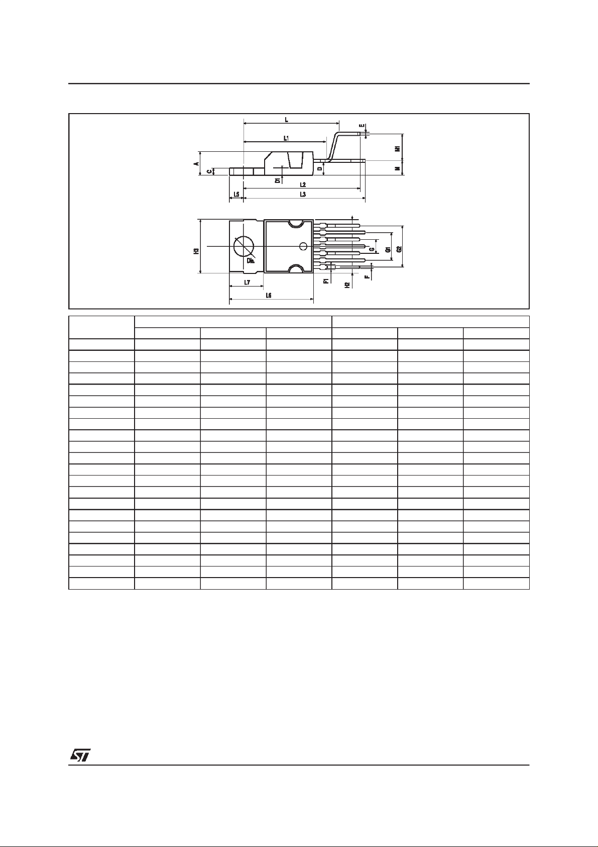
PACKAGEMECHANICAL DATA :
7 PINS- PLASTICHEPTAWATT
Dimensions Millimeters Inches
Min. Typ. Max. Min. Typ. Max.
A 4.8 0.189
C 1.37 0.054
D 2.4 2.8 0.094 0.110
D1 1.2 1.35 0.047 0.053
E 0.35 0.55 0.014 0.022
F 0.6 08 0.024 0.031
F1 0.9 0.035
G 2.41 2.54 2.67 0.095 0.100 0.105
G1 4.91 5.08 5.21 0.193 0.200 0.205
G2 7.49 7.62 7.8 0.295 0.300 0.307
H2 10.4 0.409
H3 10.05 10.4 0.396 0.409
L 16.97 0.668
L1 14.92 0.587
L2 21.54 0.848
L3 22.62 0.891
L5 2.6 3 0.102 0.118
L6 15.1 15.8 0.594 0.622
L7 6 6.6 0.236 0.260
M 2.8 0.110
M1 5.08 0.200
Dia. 3.65 3.85 0.144 0.152
Information furnished is believed to be accurate and reliable. However, STMicroelectronics assumes no responsibility for the
consequences of use of such information nor for anyinfringement of patents or other rights of thirdparties which may result from
its use. No licence is granted by implicationor otherwise under any patent or patent rights of STMicroelectronics. Specifications
mentioned in this publication are subject to change without notice. This publication supersedes and replaces all information
previouslysupplied.STMicroelectronicsproducts are notauthorizedfor useas critical componentsin lifesupportdevicesor systems
without express writtenapproval of STMicroelectronics.
The ST logo is a registered trademark of STMicroelectronics
PM-HEPTV.EPS
HEPTV.TBL
1998 STMicroelectronics - All RightsReserved
Purchase of I
Rights to use these components in a I
Australia - Brazil - Canada- China - France - Germany - Italy- Japan - Korea- Malaysia - Malta- Mexico - Morocco - The Netherlands
2
C Components of STMicroelectronics, conveys a license under the Philips I2C Patent.
2
the I
C StandardSpecificationsas defined by Philips.
STMicroelectronics GROUP OF COMPANIES
Singapore - Spain- Sweden - Switzerland- Taiwan- Thailand - United Kingdom - U.S.A.
2
C system,is granted provided that the system conforms to
5/5
 Loading...