

Page 1
STV2001
I2C SINGLE FREQUENCY DEFLECTION PROCESSOR
AND 120 MHz RGB PREAMPLIFIER
TARGET SPECIFICATION
FEATURES
Horizontal deflection
■ Single Frequ enc y, Se lf Adapt ive Os c illa tor.
■ TTL compatible positive going sync.
■ Chip does not accept sync on RGB or any video
signal.
2
■ I
C controlled: H-position, pin cushion,
keystone, parallelogram, side pin balance.
2
■ I
C controlled EW corner : top and bottom
corrections.
2
■ I
C controlled corner: top and bottom phase
corrections.
■ EW output
2
■ I
C controlled H-amplitude
■ DC controlled H-width breath ing comp ensation
■ Xray shut-down on ABL, H output latch, reset by
■ Soft start on H-duty.
Ver tical deflection
■ Vertical ramp generator.
■ Wide range AGC loop.
■ TTL compatible positive going sync, no extra
■ I
■ I
■ DC controlled height breathing compensation
■ Vertical dynamic focus output with fixed
Video preamplifier
■ 3-Channel 120MHz bandwidth video amplifier.
■ 3.5ns typical rise and fall time at 2.5V
■ I
■ I
■ Activation of ABL results in contrast gain
2
with I
C controlled gain (0.5x to 2x).
power OFF/ON.
pulses.
2
C controlled vertical position.
2
C controlled S linearity correction.
2
with I
C controlled gain (0.5X TO 2X).
amplitude (1Vpp).
.
2
C controlled individual RGB contrast
PP
(8bit)>8db
2
C controlled overall brightness.
decrease.
■ Gain window (1.5X) controlled by input pulse
2
and I
C. Pulse height controls the gain variation
from 1x to 1.5x.
■ 0.514V typical video input signal for normal
display.
2
■ I
C controlled contrast (7bits) update during
vertical retrace time.
2
C main features
I
2
■ I
C interface (slave) 100kHz max.
2
■ All I
C controlled DAC are 7 bits, except R GB
gain.
■ Power on reset on 5 V (V
DD
).
Supply voltage & power
■ 5 V/10.5 V dual supply.
■ Max power consumption: 1.2W
DESCRIPTION
The STV2001 is an I2C-controlled monolithic
integrated circuit assembled in a TQF P44 plastic
package. It combines both a deflection block
(horizontal and vertical, single frequency with very
powerful geometry correction) and a 120MHz
RGB pre-amplifier.
TQFP44/SLUG DOWN
ORDER CODE :
Version 1.2
May 2000 1/46
This is preliminary information on a new product now in development. Details are subject to change without notice.
1
Page 2

TABLE OF CONTENTS
1 - PIN CONNECTIONS . . . . . . . . . . . . . . . . . . . . . . . . . . . . . . . . . . . . . . . . . . . . . . . . . . . . . . . . . . 4
2 - PIN DESCRIPTION . . . . . . . . . . . . . . . . . . . . . . . . . . . . . . . . . . . . . . . . . . . . . . . . . . . . . . . . . . . 5
3 - BLOCK DIAGRAM . . . . . . . . . . . . . . . . . . . . . . . . . . . . . . . . . . . . . . . . . . . . . . . . . . . . . . . . . . . 6
4 - ABSOLUTE MAXIMUM RATINGS . . . . . . . . . . . . . . . . . . . . . . . . . . . . . . . . . . . . . . . . . . . . . . . 7
5 - THERMAL DATA . . . . . . . . . . . . . . . . . . . . . . . . . . . . . . . . . . . . . . . . . . . . . . . . . . . . . . . . . . . . 7
6 - SYNC INPUT . . . . . . . . . . . . . . . . . . . . . . . . . . . . . . . . . . . . . . . . . . . . . . . . . . . . . . . . . . . . . . . . 7
7 - I2C READ/WRITE . . . . . . . . . . . . . . . . . . . . . . . . . . . . . . . . . . . . . . . . . . . . . . . . . . . . . . . . . . . . 8
8 - HORIZONTAL SECTION . . . . . . . . . . . . . . . . . . . . . . . . . . . . . . . . . . . . . . . . . . . . . . . . . . . . . . 8
9 - VERTICAL SECTION . . . . . . . . . . . . . . . . . . . . . . . . . . . . . . . . . . . . . . . . . . . . . . . . . . . . . . . . 10
10 - VIDEO PRE-AMP SECTION . . . . . . . . . . . . . . . . . . . . . . . . . . . . . . . . . . . . . . . . . . . . . . . . . . 13
11 - LOGIC SECTION . . . . . . . . . . . . . . . . . . . . . . . . . . . . . . . . . . . . . . . . . . . . . . . . . . . . . . . . . . 15
12 - I2C BUS ADDRESS TABLE . . . . . . . . . . . . . . . . . . . . . . . . . . . . . . . . . . . . . . . . . . . . . . . . . . 16
13 - TYPICAL OUTPUT WAVEFORMS . . . . . . . . . . . . . . . . . . . . . . . . . . . . . . . . . . . . . . . . . . . . . 19
14 - OPERATING DESCRIPTION . . . . . . . . . . . . . . . . . . . . . . . . . . . . . . . . . . . . . . . . . . . . . . . . . 24
14.1 -GENERAL CONSIDERATIONS . . . . . . . . . . . . . . . . . . . . . . . . . . . . . . . . . . . . . . . . . . . . 24
14.1.1 -Power Supply . . . . . . . . . . . . . . . . . . . . . . . . . . . . . . . . . . . . . . . . . . . . . . . . . . . . 24
14.1.2 -I
14.1.3 -Write Mode . . . . . . . . . . . . . . . . . . . . . . . . . . . . . . . . . . . . . . . . . . . . . . . . . . . . . . 24
14.1.4 -Read Mode . . . . . . . . . . . . . . . . . . . . . . . . . . . . . . . . . . . . . . . . . . . . . . . . . . . . . . 24
14.1.5 -Sync Processor . . . . . . . . . . . . . . . . . . . . . . . . . . . . . . . . . . . . . . . . . . . . . . . . . . . 24
14.1.6 -IC Status . . . . . . . . . . . . . . . . . . . . . . . . . . . . . . . . . . . . . . . . . . . . . . . . . . . . . . . . 24
14.1.7 -Sync Inputs . . . . . . . . . . . . . . . . . . . . . . . . . . . . . . . . . . . . . . . . . . . . . . . . . . . . . . 24
14.1.8 -Sync Processor Output . . . . . . . . . . . . . . . . . . . . . . . . . . . . . . . . . . . . . . . . . . . . . 25
14.2 -HORIZONTAL PART . . . . . . . . . . . . . . . . . . . . . . . . . . . . . . . . . . . . . . . . . . . . . . . . . . . . 25
14.2.1 -Internal Input Conditions . . . . . . . . . . . . . . . . . . . . . . . . . . . . . . . . . . . . . . . . . . . . 25
14.2.2 -PLL1 . . . . . . . . . . . . . . . . . . . . . . . . . . . . . . . . . . . . . . . . . . . . . . . . . . . . . . . . . . . 25
14.2.3 -PLL2 . . . . . . . . . . . . . . . . . . . . . . . . . . . . . . . . . . . . . . . . . . . . . . . . . . . . . . . . . . . 27
14.2.4 -Output Section . . . . . . . . . . . . . . . . . . . . . . . . . . . . . . . . . . . . . . . . . . . . . . . . . . . 27
14.2.5 -X-RAY Protection . . . . . . . . . . . . . . . . . . . . . . . . . . . . . . . . . . . . . . . . . . . . . . . . . 28
14.3 -VERTICAL PART . . . . . . . . . . . . . . . . . . . . . . . . . . . . . . . . . . . . . . . . . . . . . . . . . . . . . . . 28
14.3.1 -Function . . . . . . . . . . . . . . . . . . . . . . . . . . . . . . . . . . . . . . . . . . . . . . . . . . . . . . . . 28
14.3.2 -I2C Control Adjustments . . . . . . . . . . . . . . . . . . . . . . . . . . . . . . . . . . . . . . . . . . . . 28
14.3.3 -Basic Equations . . . . . . . . . . . . . . . . . . . . . . . . . . . . . . . . . . . . . . . . . . . . . . . . . . 29
14.3.4 -Geometric Corrections . . . . . . . . . . . . . . . . . . . . . . . . . . . . . . . . . . . . . . . . . . . . . 29
14.3.5 -E/W . . . . . . . . . . . . . . . . . . . . . . . . . . . . . . . . . . . . . . . . . . . . . . . . . . . . . . . . . . . . 32
14.3.6 -Dynamic Horizontal Phase Control . . . . . . . . . . . . . . . . . . . . . . . . . . . . . . . . . . . . 32
14.3.7 -Vertical Dynamic Focus . . . . . . . . . . . . . . . . . . . . . . . . . . . . . . . . . . . . . . . . . . . . 32
14.3.8 -Corner Correction . . . . . . . . . . . . . . . . . . . . . . . . . . . . . . . . . . . . . . . . . . . . . . . . . 32
14.3.9 -Horizontal Breathing . . . . . . . . . . . . . . . . . . . . . . . . . . . . . . . . . . . . . . . . . . . . . . . 32
14.3.10 -Vertical Breathing . . . . . . . . . . . . . . . . . . . . . . . . . . . . . . . . . . . . . . . . . . . . . . . . 32
14.4 -GENERAL CONSIDERATIONS . . . . . . . . . . . . . . . . . . . . . . . . . . . . . . . . . . . . . . . . . . . . 32
14.4.1 -Input Stage . . . . . . . . . . . . . . . . . . . . . . . . . . . . . . . . . . . . . . . . . . . . . . . . . . . . . . 3 2
14.4.2 -Contrast Adjustment (7 bits) . . . . . . . . . . . . . . . . . . . . . . . . . . . . . . . . . . . . . . . . . 33
14.4.3 -ABL Control . . . . . . . . . . . . . . . . . . . . . . . . . . . . . . . . . . . . . . . . . . . . . . . . . . . . . . 33
14.4.4 -Brightness Adjustment (6 bits) . . . . . . . . . . . . . . . . . . . . . . . . . . . . . . . . . . . . . . . 33
14.4.5 -Drive Adjustment (3 x 8 bits) . . . . . . . . . . . . . . . . . . . . . . . . . . . . . . . . . . . . . . . . . 33
14.4.6 -Output Stage . . . . . . . . . . . . . . . . . . . . . . . . . . . . . . . . . . . . . . . . . . . . . . . . . . . . . 33
14.4.7 -Bright Window . . . . . . . . . . . . . . . . . . . . . . . . . . . . . . . . . . . . . . . . . . . . . . . . . . . . 35
2
C Control . . . . . . . . . . . . . . . . . . . . . . . . . . . . . . . . . . . . . . . . . . . . . . . . . . . . . . 24
3
2/3
2
Page 3

14.4.8 -Blanking Generator . . . . . . . . . . . . . . . . . . . . . . . . . . . . . . . . . . . . . . . . . . . . . . . . 35
14.5 -GENERAL CONSIDERATIONS . . . . . . . . . . . . . . . . . . . . . . . . . . . . . . . . . . . . . . . . . . . . 36
14.5.1 -POR (Power On Reset) - Subad. 11-D8 . . . . . . . . . . . . . . . . . . . . . . . . . . . . . . . . 36
14.5.2 -Supply Voltage Threshold. . . . . . . . . . . . . . . . . . . . . . . . . . . . . . . . . . . . . . . . . . . 36
14.5.3 -Video Off (I2C control) - Subad. 00-D8 . . . . . . . . . . . . . . . . . . . . . . . . . . . . . . . . . 36
14.5.4 -Vertical Output Off . . . . . . . . . . . . . . . . . . . . . . . . . . . . . . . . . . . . . . . . . . . . . . . . 36
14.5.5 -X-Ray, Set Operation - Subad. 09-D8 . . . . . . . . . . . . . . . . . . . . . . . . . . . . . . . . . 36
15 - INTERNAL SCHEMATICS . . . . . . . . . . . . . . . . . . . . . . . . . . . . . . . . . . . . . . . . . . . . . . . . . . . 37
16 - PACKAGE MECHANICAL DATA . . . . . . . . . . . . . . . . . . . . . . . . . . . . . . . . . . . . . . . . . . . . . . 45
3/3
Page 4
STV2001
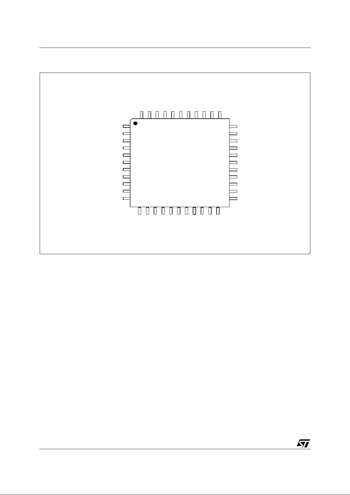
1 - PIN CONNECTIONS
Hin
Vin
Vref
VAGCCAP
VGND
VCAP
Vout
VRB
VAVcc
OUT1
AGND
FC1
FILTER
44 43 42 41 40 39 38 37 36 35 34
1
2
3
4
5
6
7
8
9
10
11
12 13 14 15 16 17 18 19 20 21 22
OUT3
OUT2
PGND
Co
Ro
PVCC
PLL1F
VBCAP
PLL2C
HGND
IN1
IN2
ABLin
VBDC
GAINWIN
Hfly
Href
Hout
33
32
31
30
29
28
27
26
25
24
23
HDGND
LGND
SAVcc
SCL
SDA
V
(5V)
DD
EWout
FCAP
HBRTHin
VBRTHin
VFOCUS
IN3
VFLYin
4/46
3
Page 5
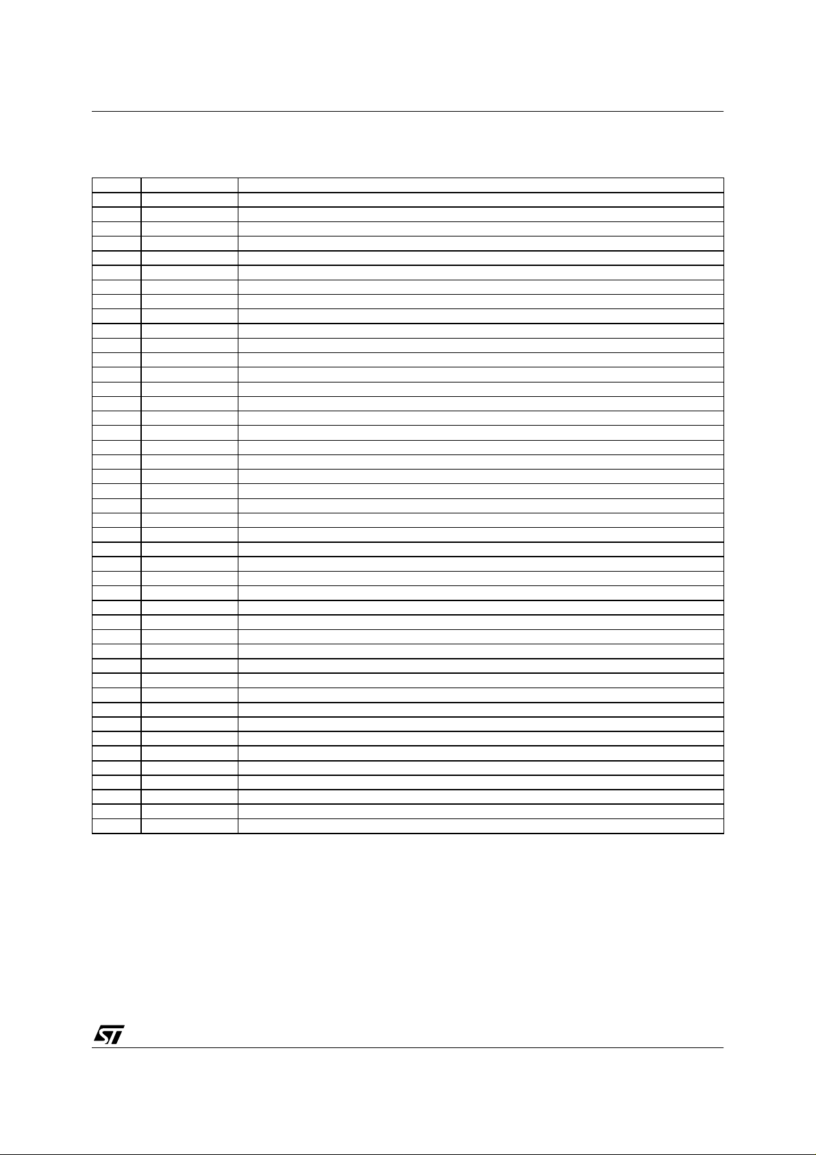
2 - PIN DESCRIPTION
Pin Name Function
1 Hin Horizontal Sync Input
2 Vin Vertical Sync Input
3 Vref Vertical Section Reference Voltage
4 VAGCCAP Vertical AGC Loop Capacitor
5 VGND Vertical Section Ground
6 VCAP Vertical Sawtooth Generator Capacitor
7 Vout Vertical Output
8 VRB Vertical Ramp Filter
9 VAVcc Video Section Analog Supply (10.5V typ)
10 OUT1 Video Output 1
11 AGND Video Analog Ground
12 OUT2 Video Output 2
13 PGND Video Section Power Ground
14 OUT3 Video Output 3
15 PVcc Video Section Power Supply (10.5V typ)
16 GAINWIN Gain Window Input
17 IN1 Video Input 1
18 VBDC Vertical Blanking Output with DC Level adjusted by DAC
19 IN2 Video Input 2
20 ABLin Video Automatic Beam Current Compensation Input
21 IN3 Video Input 3
22 VFLYin Vertical Fly Back Pulse Input
23 VFOCUS Vertical Dynamic Focus Output
24 VBRTHin Vertical Breathing DC Input
25 HBRTHin Horizontal Breathing Compensation DC Input
26 FCAP Filter Capacitor
27 EWout EW Output
28 V
29 SDA I
30 SCL I
31 SAVcc Scanning Section Analog Supply (10.5Vtyp)
32 LGND Bus and Scanning Power Ground
33 HDGND H Driver Output Ground
34 Hout Horizontal Driver Output, open collector
35 Href Horizontal Section Reference Voltage
36 Hfly Horizontal Flyback Input, Positive
37 HGND Horizontal Section Ground
38 PLL2C PLL2 Loop Filter
39 VBCAP PLL2 Top Comparator Filter
40 PLL1F PLL1 Loop Filter
41 Ro Horizontal Oscillator Resistor
42 Co Horizontal Oscillator Capacitor
43 FC1 PLL1 Filter Capacitor
44 FILTER Horizontal Filter Capacitor (HPOS)
DD
Bus, Scanning Logic and Video Logic Supply (5V typ)
2
C Data Input
2
C Clock Input
STV2001
5/46
Page 6

6/46
3 - BLOCK DIAGRAM
STV2001
SAV
CC
Href
Vref
Hin
Vin
HGND
VGND
VCAP
VAGCCAP
VRB
Vout
VFOCUS
SDA
SCL
VDD
LGND
IN1
IN2
GAINWIN
IN3
31
35
3
1
2
37
5
6
4
8
7
23
29
30
28
32
17
19
16
21
Href
Scorr
Hsync
Gain
WIndow
PLL1F FILTER FC1 Ro Co HFly PLL2C Hout
40
Vref
Vpos
VOSC
RAMP
Generator
VDF
2
C BUS
I
DECODER
Clamp
44 43 41 42 36 38
Phase
Freq
Comp
Vamp
VCO
Corner
Phase
Geometry
Tracking
EW
Corner
LATCHES & DACs
BrightnessContrast
Phase
Comp
2
X
KeyBal
X
SPB
Drive
VBCAP
39
Phase
Shifter
X
+
HFly
Hsync
Vsync
EWPCC
2
KEYST
34 33
HOUT
Buffer
EW OUTPUT
H Breathing
+
Blanking
BPCP
Output
Stage
HDGND
Safety
VFBack
EHTcomp
AMP
ABL
EWout
27
FCAP
26
22
VFLYin
18
VBDC
25
HBRTHin
VBRTHin
24
VAV
9
OUT 1
10
AGND
11
PV
15
12
OUT 2
ABLin
20
PGND
13
OUT 3
14
CC
CC
STV2001
Page 7
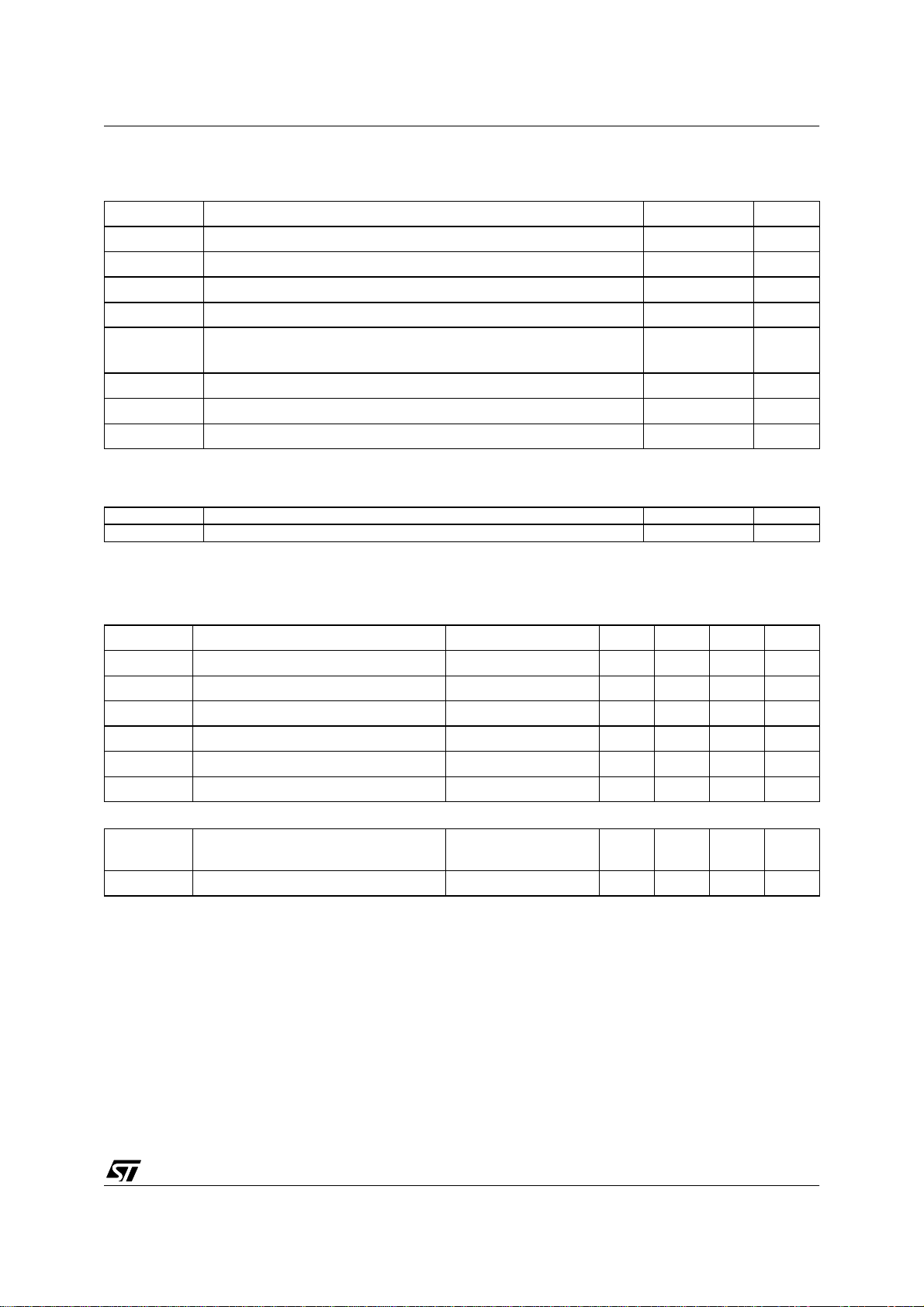
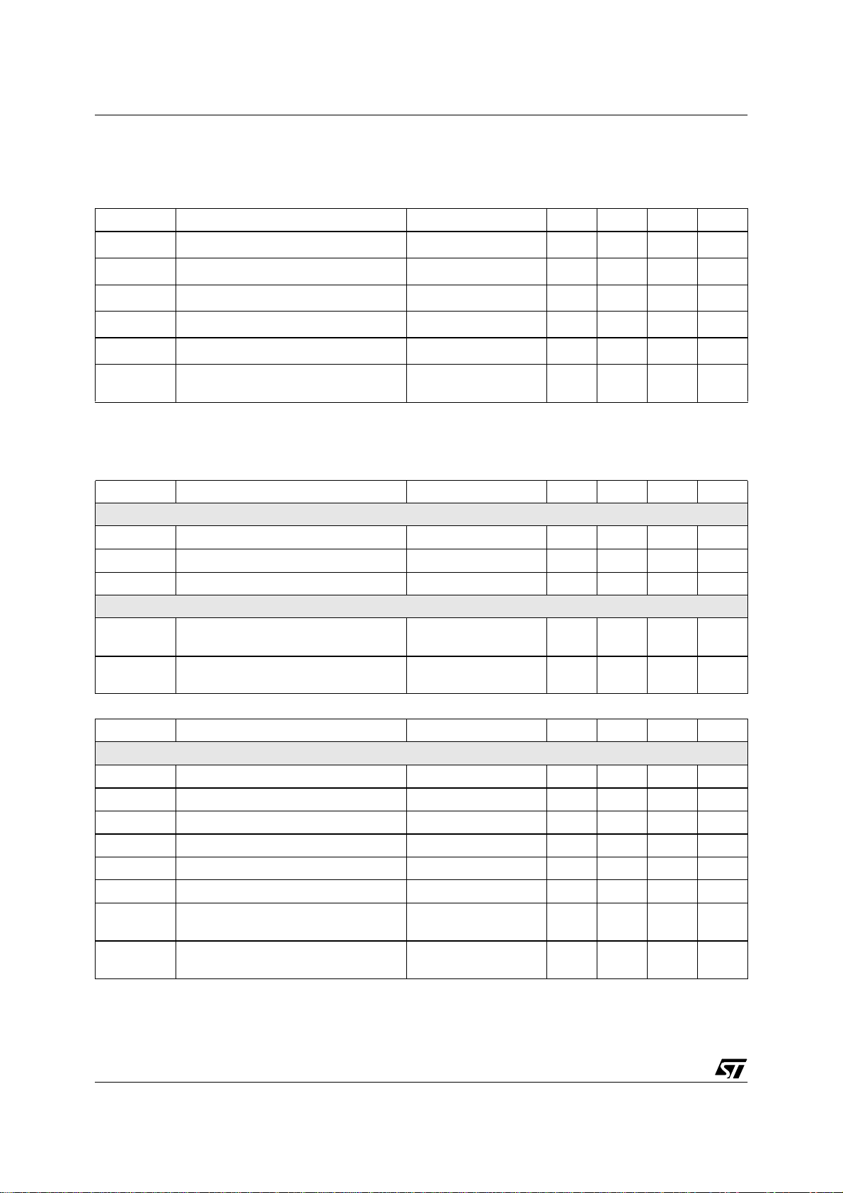
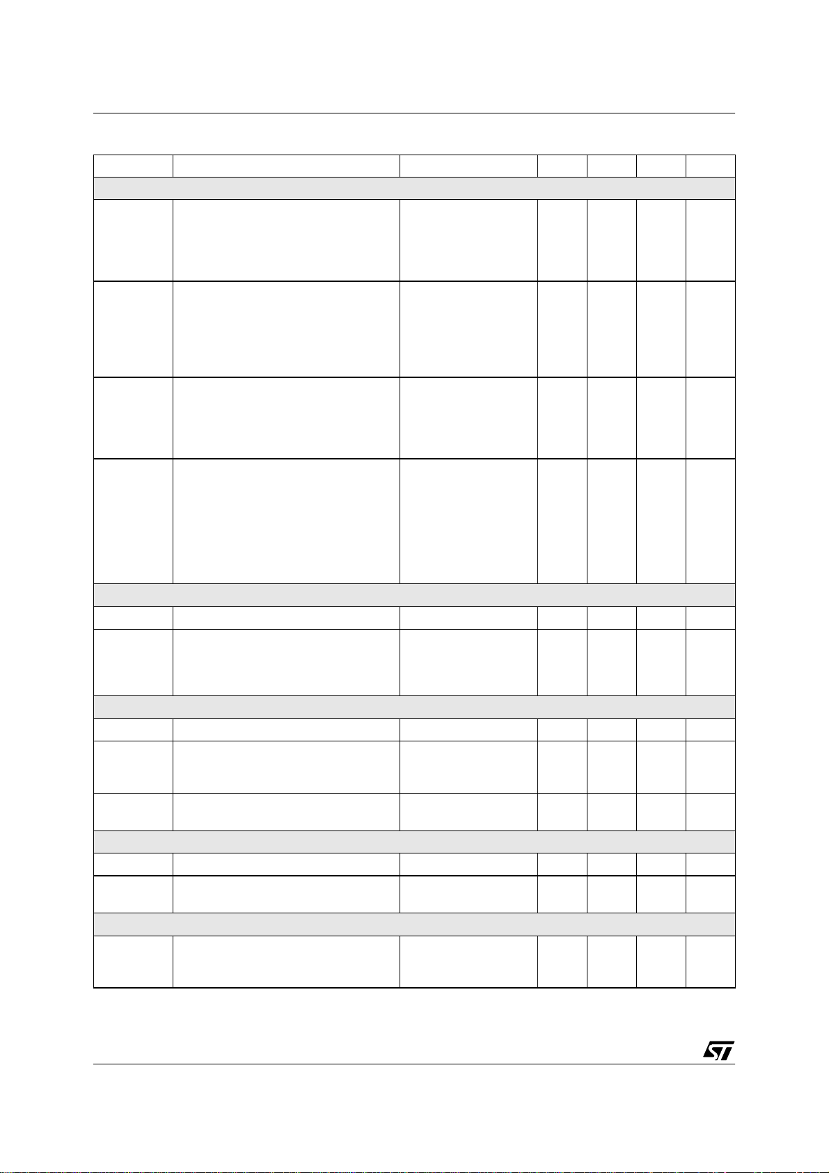
4 - ABSOLUTE MAXIMUM RAT INGS
Symbol Parameter Value Unit
SAVcc Scanning Section Analog Supply Voltage 13.5 V
VAVcc Video Section Analog Supply Voltage 13.5 V
PVcc Supply Voltage for Video Pre-Amp Section 13.5 V
Vdd Logic Section Supply Voltage 5.5 V
V
ESD
Tstg Storage Temperature -40 to 150
Tj Junction Temperature 150
Toper Operating Temperature (Device ambient) 0 to 70
ESD susceptibility HBM model 100pF & 1.5kΩ
EIAJ Norm 200pF & 0Ω
2
300
5 - THERMAL DAT A
STV2001
kV
V
o
C
o
C
o
C
Symbol Parameter Value Unit
R
TH(j-a)
Junction to Ambient Thermal Resistance (MAX) 46
6 - SYNC INPUT
Operating Conditions (V
Symbol Parameter Test Conditions Min Typ Max Unit
HSVR Voltage on Hin 0 5 V
MinD Min Hin pulse duration 0.7 us
Mduty Max Hin Duty Cycle 25 %
VSVR Voltage on Vin 0 5 V
VSW Min Vin pulse duration 5 us
VSD Max Vin Duty Cycle 15 %
Electrical Characteristics (VDD = 5V, T
V
INTH
RIN Horizontal & Vertical Pull-Up Resistor 200 kΩ
Horizontal & Vertical Input Logic Level Low Level
= 5V, T
DD
amb
= 25°C)
= 25°C)
amb
0.8 V
High Level 2.2
o
C/W
V
7/46
Page 8
STV2001
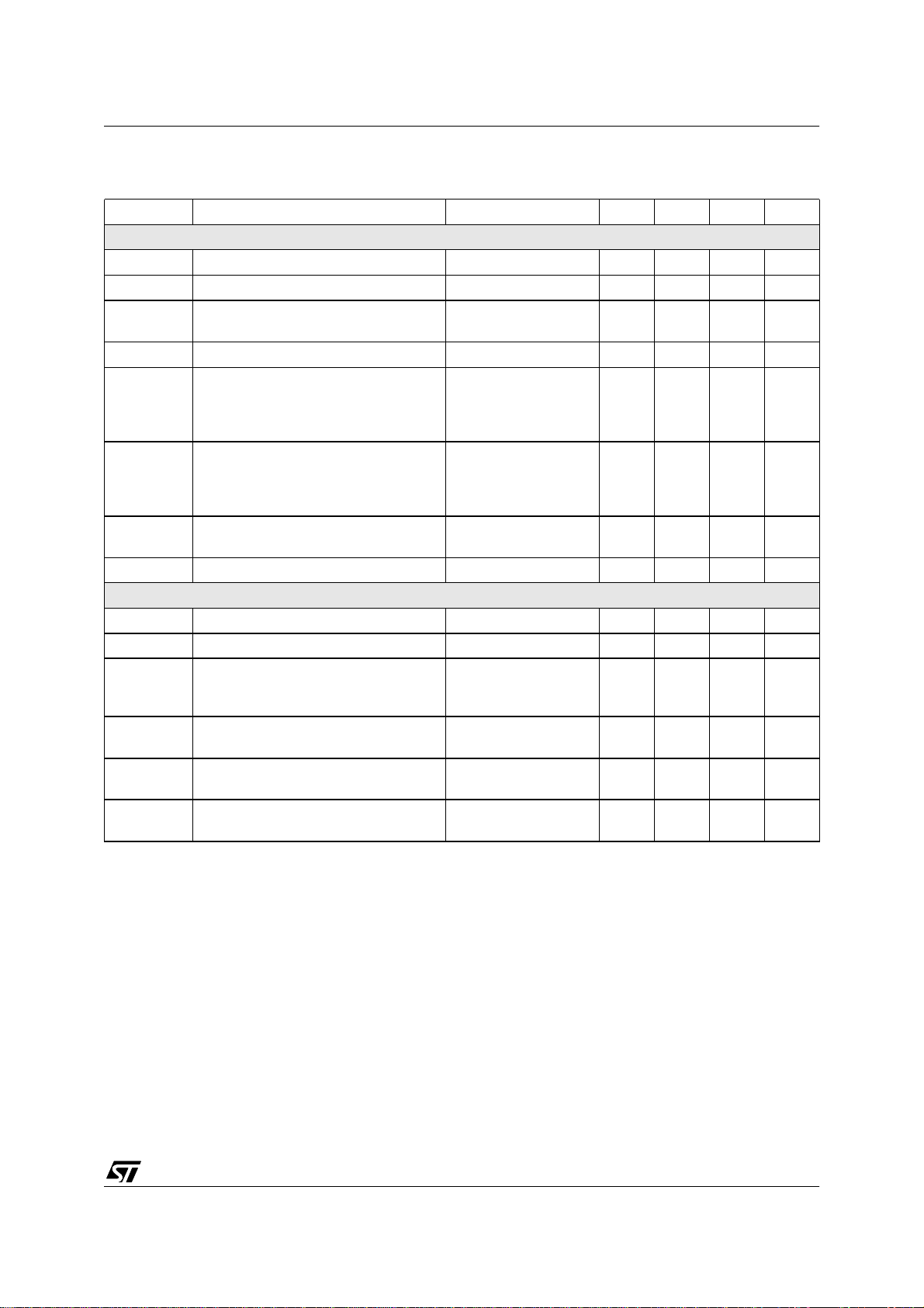
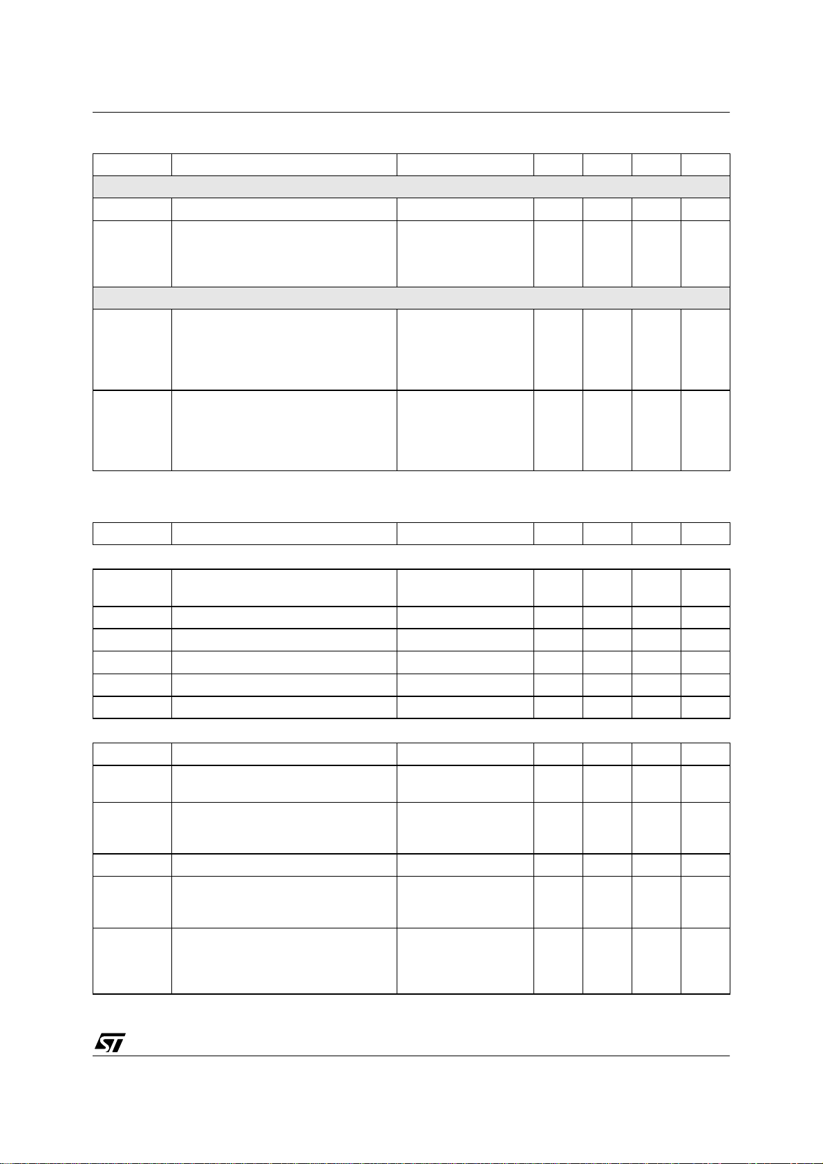
7 - I2C READ /WRITE
Electrical Characteristics (VDD = 5V, T
amb
= 25°C)
Symbol Parameter Test Conditions Min Typ Max Unit
F
T
T
HIGH
V
V
V
SCL
LOW
INL
INH
ACK
Maximum Clock Frequency 100 kHz
Low Period of the SCL Clock 1.3 us
High Period of SCL Clock 0.6 us
SDA & SCL Input Low Level Voltage 1.5 V
SDA & SCL Input High Level Voltage 3 V
Acknowledge Output Voltage on SDA
input with 3mA
0.4 V
8 - HORIZONTAL SECTION
Operating Conditions
Symbol Parameter Test Conditions Min Typ Max Unit
VCO
Ro(min) Minimum Oscillator Resistor 6 kΩ
Co(min) Minimum Oscillator Capacitor 390 pF
Fmax Maximum Oscillator Frequency 150 kHz
OUTPUT SECTION
I
HFB
I
HOUT
Horizontal FlyBack Input Maximum
Current
Horizontal Drive Output Maximum Sink
Current
5mA
15 mA
Electrical Characteristics (VDD = 5V, T
amb
= 25°C)
Symbol Parameter Test Conditions Min Typ Max Unit
SUPPLY AND REFERENCE VOLTAGES
Vcc Supply Voltage 9.5 10.5 11.5 V
Vdd Supply Voltage 4.5 5 5.5 V
Icc Supply Current 30 mA
Idd Supply Current 5 mA
V
HREF
Horizontal Reference Voltag e I=-2mA 7.4 8 8.6 V
VVREF Vertical Reference Voltage I=-2mA 7.4 8 8.6 V
I
HREF
I
VREF
Horizontal Reference Maxim um Source
Current
Vertical Reference Maximum Source
Current
5mA
5mA
8/46
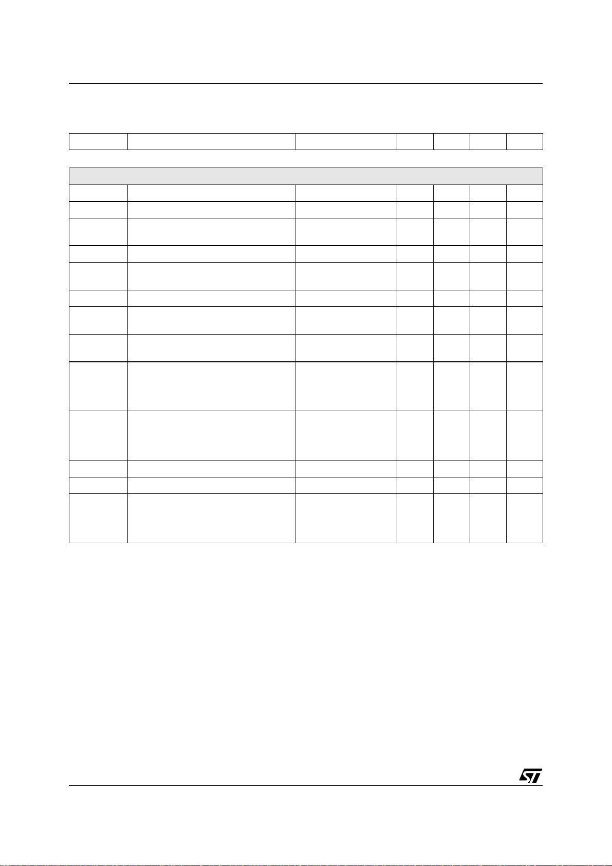
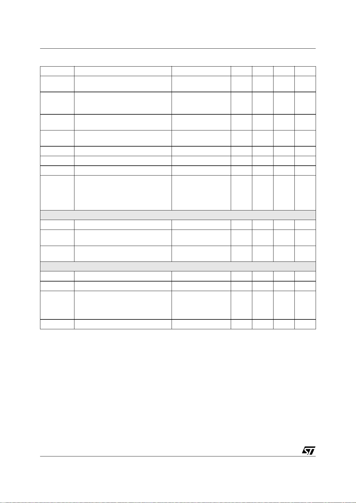
Page 9
STV2001
Operating Conditions
Symbol Parameter Test Conditions Min Typ Max Unit
1st PLL SECTION
V
clamp
V
VCO
A
VCO
H
PHASE
VPMIN
VPTYP
VPMAX
I
PLL1-UL
I
PLL1-L1
I
PLL1-L2
f
O
dfo/dT Free Running Frequency Thermal Drift -150 ppm/
2nd PLL SECTION & HORIZONTAL OUTPUT SECTION
V
THFB
Jitter
H
DC
Vphi2 Internal Clamp Level on PLL2 Filter
VSCinh
Vsat
VCO clamp Voltage range V
VCO clamp Voltage, at POR V
VCO Gain
=8V 3.0 3.8 V
HREF
=8V 3.8 V
HREF
Ro=4868Ω, Co=820pF,
dF/dV=1/11RoCo
23 kHz/V
Horizontal Phase Adjustment Range % of Horizontal Period +/-10 %
Horizontal Phase Setting
Minimum
Typical
Maximum
PLL1 Charge Pump Current
Unlocked
Locked
Locked
Free Running Frequency, no input
at POR, lower clamp voltage at max.
SubAdd 07
X1111111
X1000000
X0000000
2.8
3.4
4.0
Sub-Address 11
+/-40
x1xx xxxx
x0xx xxxx
+/-1
±300
Ro=4868Ω, Co=820pF 86 kHz
Flyback Input Threshold Voltage 0.65 0.75 V
Horizontal Jitter At 80KHz 70 ppm
H
Horizontal Drive Output Duty Cycle
(Ratio of Power Transistor OFF time to
55 %
Period)
Threshold Voltage to Stop H-Out, V-Out,
Reset ABL when Vcc<VSCinh
Horizontal Drive Output Saturatio n
HD
Voltage
Low Level
High Level
Iout=15mA 0.4 V
1.6
4.0
6.9 V
V
V
V
µA
mA
µA
V
V
o
C
9/46
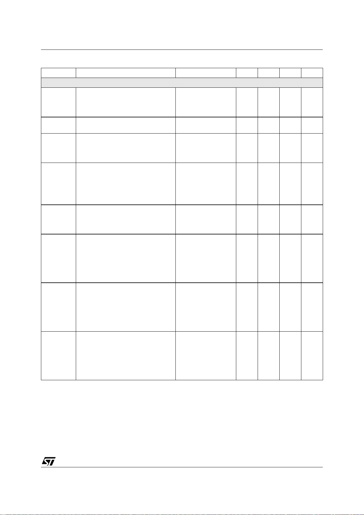
Page 10
STV2001
9 - VERTICAL SECTION
Symbol Parameter Test Conditions Min Typ Max Unit
Electrical Characteristics (VDD = 5V, T
amb
VERTICAL RAMP SECTION
V
RBOT
V
RTOP
V
RTOPF
T
VDIS
F
FRV
Voltage at Ramp Bottom Point V
Voltage at Ramp Top Point with Sync V
Voltage at Ramp Top Point without Sync V
Vertical Sawtooth Discharge Time C
Vertical Free Running Frequency
(S correction inhibited)
ASFR Auto- Sync Frequ ency Range C
RAFD
R
LIN
V
POS
Ramp Amplitude Drift Versus Frequency
at Maximum Vertical Amplitude
Ramp Linearity at Vcap pin
with S Correction inhibited
Vertical Position Adjustment Voltage
with V
mean value
OUT
VOR Vertical Output Peak to Peak Voltage
I
VOUT
V
VRB
Vertical Output Maximum Current +/-5 mA
Vertical Ramp Filter Voltage 2 V
Max Vertical S-Correction Amplitude
dVS
S-Correction inhibited, DV/Vpp at TV/4
S-correction Maximum,
DV/Vpp at 3TV/4
= 25°C)
=8V 2 V
VREF
=8V 5 V
VREF
-
V
=8V
VREF
=150nF 70 µs
OSC
C
=150nF 100 Hz
OSC
=150nF 50 16 5 Hz
OSC
C
=150nF 50Hz -
OSC
165Hz
2.5V < VOSC < 4.5V 0.5 %
Sub-Add=09
X0000000
X1000000
X1111111 3.65
Sub-Add=08
10000000
11000000
11111111 3.5
Sub-Add 0A
0XXXXXXX
11111111
RTOP
0.1
200 ppm/Hz
3.2
3.5
3.8
2.25
3
3.75
-4
+4
V
3.3 V
V
V
2.5 V
V
V
%
%
10/46
Page 11
STV2001
Symbol Parameter Test Conditions Min Typ Max Unit
EAST/WEST FUNCTION (available without feedback connection)
DC Output Voltage with:
EW
DC
TDEW
DC
EW
PARA
EW
track
KeyAdj
KeyTrack
EW Corner
Top
EW Corner
Bottom
-Typical VPOS and Keystone inhibited
-External driver connected as unity gain
buffer
DC Output Voltage Thermal Drift
(Non-test Parameter)
Parabola Amplitude with:
-Max VAMP
-Typ VPOS
-Keystone inhibited
Parabola Amplitude Function of VAMP
Control (tracking between VAMP & EW)
with:
-Typ VPOS=typ.
-Keystone=typ.
-EW Amplitude=typ.
Keystone Adjustment Capa bility with:
-VPOS=typ.
-EW= inhibited
-Vertical Amplitude= Max.
Intrinsic Keystone Function of VPOS
Control (tracking between VPOS and
EW) with :
-EW Amplitude= Max
-Vertical Amplitude=Max
A/B Ratio
B/A Ratio
Corner Adjustment capability with :
-VPS=typ,
-EW = inhibited
-VAMP = max
-HSize = Min
-HBreath>VREF
-Keystone = inhibited
Corner Adjustment capability with :
-VPS=Typ,
-EW = inhibited
-VAMP = Max
-HSize = Min
-HBreath>VREF
-Keystone = inhibited
Sub-add 0C
11111111
11000000
10000000
Sub-address 08
10000000
11000000
11111111
Sub-address 0B
10000000
11111111
Sub-address 09
X0000000
X1111111
Sub-address 04
1111 1111
1100 0000
1000 0000
Sub-address 15
1111 1111
1100 0000
1000 0000
2.0 V
100 ppm/
1.0
0.5
0
0.18
0.35
0.57
0.2
0.2
0.52
0.52
+1.25
0
-1.25
+1.25
0
-1.25
V
V
V
V
V
V
V
pp
V
pp
Vpp
Vpp
Vpp
Vpp
Vpp
Vpp
o
C
11/46
Page 12
STV2001
Symbol Parameter Test Conditions Min Typ Max Unit
INTERNAL DYNAMIC HORIZONTAL PHASE CONTROL
Side Pin Balance Parabola Amplitude
with:
SBPpara
-VAMP=Max,
-VPOS=typ.
-Parallelogram inhibited
Side Pin Balance Parabola Amplitude
function of VAMP Control (tracking be-
SPBtrack
tween VAMP & SPB) with
-SPB=Max
-VPO=typ.
-Parallelogram= inhibi ted
Parallelogram Adjustment Capability
with:
ParAdj
-VAMP=Max
-POS =Typ
-SPB=Max
Intrinsic Parallelogram Function of
VPOS Control (tracking between VPOS
and DHPC) with
Partrack
-VAMP=Max
-SPB=Max
-Parallelogram= inhibi ted
A/B Ratio
B/A Ratio
VERTICAL BREATHING COMPENSATION
VBRrng Input DC Breathing Control Range 1 10.5 V
Vertical Size Compensation
VSC
Variation of V output vs full range of
VBRrng
VERTICAL DYNAMIC FOCUS OUTPUT
VDF
DC Output Level RL=10kΩ 4V
DC
VDF Parabola Amplitude with:
VDFamp
Vamp = typ
VPOS = typ.
V
FOCPOL
Parabola Polarity at Output =
Inverted “U”
VERTICAL FLYBACK INPUT
V
FLYTH
V
FLYINH
Vertical Flyback Threshold 1 V
Inhibition of Vertical Flyback input
(id pulse in action instead of VFlyback)
HORIZONTAL SIZE CONTROL
Hsize Hsize output DC voltage
sitting on top of EWDC=2.0V
Sub-add 0E
11111111
10000000
Sub-add 08
10000000
11000000
11111111
Sub-add 0F
11111111
10000000
Sub-add 09
X0000000
X1111111
Sub-address 14
XX00 0000
X100 0000
XX11 1111
sub-add 0D
X0000000
X1111111
+1.4
-1.4
0.5
0.9
1.4
+1.4
-1.4
0.52
0.52
-5
-20
1 Vpp
6.5 V
0
2.4
%T
%T
%T
%T
%T
%T
%T
%
%
%
H
H
H
H
H
H
H
V
V
12/46
Page 13
STV2001
Symbol Parameter Test Conditions Min Typ Max Unit
HORIZONTAL BREATHING COMPENSATION
HBRrng Breathing input DC Control Range 1 10.5 V
Horizontal size compensation, EW DC
HSC
voltage variation under full range of
HBRrng
CORNER PHASE CORRECTION
Corner Phase Top Adjustment with:
Corner
Phase Top
Vamp = max
Vpos = Typ.
SPB = OFF
Parrallelogram = OFF
Corner Phase Bottom Adjustment with:
Corner
Phase
Bottom
Vamp = max
Vpos = Typ.
SPB = OFF
Parrallelogram = OFF
Sub-address 12
X000 0000
X100 0000
X111 1111
Sub-address 05
1000 0000
1111 1111
Sub-address 06
0000 0000
0111 1111
0.2
0.8
-2.8
+2.8
-2.8
+2.8
V
V
%
%
%
%
10 - VIDEO PRE-A MP SECTION
Symbol Parameter Test Conditions Min Typ Max Unit
DC Electrical Characteristics (VAV
VAV
cc
Video Section Analog Supply Voltage
PVcc Power Section Supply Voltage 9.5 10.5 11.5 V
IS Supply Current of VAVcc & PVcc 63 mA
V
V
V
IN
OUT
Black
Video Input Voltage Amplitude 0.7 1 Vpp
Typical Output Voltage Range 0.5 7 V
Output (Black level) 1.5 V
AC Electrical Characteristics (VAVCC = PV
Symbol Parameter Condition Min Typ Max Unit
AV Maximum Gain
CAR Contrast Attenuation Range
DAR Drive Attenuation Range 30 dB
GM Gain Match
BW Large Signal Bandwidth
CC
= PV
= 10.5V, Tamb = 25oC)
CC
9.5 10.5 11.5 V
= 10.5V, CL = 5pF, RL = 1KΩ, Tamb = 25oC)
CC
Max Contrast and Drive
2
I
C Gainwin = 1
V
= 0.7Vpp
IN
Contrast and Drive at
18 dB
30 dB
POR
V
= 0.7Vpp,
IN
V
= 4Vpp, Contrast
OUT
+-0.1 dB
and Drive= 0.87Max
V
=0.7Vpp,
IN
= 2.5Vpp, Contrast
V
OUT
and Drive = 0.87Max
120 MHz
At -3dB
13/46
Page 14
STV2001
Symbol Parameter Test Conditions Min Typ Max Unit
DIS Video Output Distortion f=1MHz, VIN=1Vpp,
V
= 1Vpp
OUT
= 0.7Vpp,
V
, t
t
R
Video Output Rise and Fall Time
F
IN
V
=2.5Vpp,Contrast
OUT
and Drive=0.87Max
dVo Overshoot of output with respect to
actual output amplitude
=5pF 5 7 %
C
LOAD
BRT Brightness max DC level
Brightness min DC level
R
L
Equivalent Load on Video Output Tj<Tj
MAX
Tsample Hold time 100 ms
Thold Sample time 1 µs
V
= 0.7Vpp,
CT Crosstalk Between Video Channels
IN
V
= 2.5Vpp,
OUT
Contrast and
44 dB
Drive=0.7Max
f=1MHz
ABL COMPENSATION
R
G
TH
ABL
ABL
ABL
ABL Input resistor 10 kΩ
ABL minimum Attenuation
ABL maximum Attenuation
ABL latch function activation threshold
(High beam current detection)
V
=5.3V
ABL
V
=2.8V
ABL
01V
GAIN WINDOW
V
INL
V
INH
Input Low Level Voltage 0.7 V
Input High Level Voltage 1.5 V
Contrast Gain Increase during High
Gain
Input
VIN = 1.5V
VIN = 5.0V
T
D
Total Delay Time 100 ns
0.3 %
3.5 4 ns
2.5
0
1kΩ
0
12
1
1.5
V
V
dB
dB
V/V
V/V
14/46
Page 15

11 - LOGIC SECTION
STV2001
DC Electrical Characteristics (VAV
Symbol Parameter Condition Min Typ Max Unit
VBDC OUTPUT SECTI ON
Blanking output high voltage 7 V
VBDC
I
BLK
T
BLK
SUPPLY VOLTAGE THRESHOLD
V
THPD1
V
THPD2
Blanking output low voltage
I2C adjustable
Output sink current 0.3 mA
Vertical blanking time
(start by VSync 2 and by VFly)
Supply first threshold voltage 8.5 V
Supply second threshold voltage 6.9 V
CC
= PV
= 10.5V, Tamb = 25oC)
CC
sub-add10
1X000000
1X111111
1
4.5
V
V
15/46
Page 16

STV2001
12 - I2C BUS ADDRESS TABLE
[0] denotes POR value, X denotes unused data bit and must be set to 0.
D8 D7 D6 D5 D4 D3 D2 D1
WRITE MODE (SLAVE ADDRESS= 8C)
Video
00
01
02
03
04
05
06
07
08
09
0A
0B
0C
0D x
0E
0F
10
1, on
[0], off
EWCorner
Top/Bottom
0 off
[1], on
Corner phase
Top/Bottom
1, on
[0],off
Ipump2
1, high
[0], low
Hout
0, off
[1], on
Vramp
0, off
[1], on
Xray
1, reset
S Select
1, on
[0], off
EW Key
0, off
[1], on
EW Select
0, off
[1], on
SPB Sel
0, off
[1], on
Parallelog
0, off
[1], on
VBDC
1, on
[0], off
[1] [0] [1] [1] [0] [1] [0]
[1] [0] [1] [1] [0] [1] [0] [0]
[1] [0] [1] [1] [0] [1] [0] [0]
[1] [0] [1] [1] [0] [1] [0] [0]
[1] [0] [0] [0] [0] [0] [0]
[1] [0] [0] [0] [0 ] [0] [0]
[1] [0] [0] [0] [0] [0] [0]
Horizontal Phase Adjustment
[1] [0] [0] [0] [0] [0] [0]
Vertical Ramp Amplitude Adjustment
[1] [0] [0] [0] [0] [0] [0]
Vertical Position Adjustment
[0]
[1] [0] [0] [0] [0] [0] [0]
[1] [0] [0] [0] [0] [0] [0]
[1] [0] [0] [0] [0] [0] [0]
[1] [0] [0] [0] [0] [0] [0]
[1] [0] [0] [0] [0] [0] [0]
[1] [0] [0] [0] [0] [0] [0]
[1] [0] [0] [0] [0] [0] [0]
Gainwin
[0], 1X
1, 1.5X
[1] [1] [1] [1] [1] [1]
Contrast
Drive 1
Drive 2
Drive 3
EW Corner Top
Corner Phase Top
Corner Phase Bottom
S Correction
Keystone
EW Amplitude
Horizontal Amplitude
Side Pin Balance
Parallelogram
Vertical Blanking DC level
16/46
Page 17

D8 D7 D6 D5 D4 D3 D2 D1
POR
11
12
13 x x x x
14
15
READ MODE (SLAVE ADDRESS = 8D)
Note: Both EW Corner Top and EW Corner Bottom are switched ON/OFF by reg (sub-address 04/D8).
[0], off
1, reset
Hlock
0, lock
[1], unlock
Ipump
1, 1mA
[0], 0.3mA
[1] [0] [0] [0] [0] [0] [0]
[1] [0] [0] [0] [0] [0] [0]
[1] [0] [1] [1] [0] [1]
HEHT Comp Gain
[1] [0] [0] [0] [0] [0]
EWCorner Bottom
Xray
1, on
[0], off
Brightness
PLL1 filter voltage clamp (FVC)
[0] [0] [0] [0]
VEHT Comp Gain
STV2001
17/46
Page 18

STV2001
Figure 1. EW Output Referred Voltage
A
EW
DC
Figure 2. Dynamic Horizontal Phase Control Output
EW
B
PARA
EW
A
DHPC
DC
SPB
Figure 3. Keystone Effect on EW Output (PCC Inhibited)
Figure 4. Vertical Dynamic FOcus Outpu t
4Vdc
PARA
PARA
B
Keyadj
18/46
Page 19

13 - TYPICAL OUTPUT WAVEFORMS
STV2001
Function
Vertical Size
Vertical
Position
Vertical
S
Linearity
Sub
Address
Pin Byte Specification Effect on Screen
1000 0000
1111 1111
x000 0000
x100 0000
x111 1111
0000 0000
Inhibited
1111 1111
V
OUTDC
V
OUTDC
V
OUTDC
= 3.2 V
= 3.5 V
= 3.8 V
∆V
2.25V
3.75V
Vpp
EW Corner
Top
(Symmetri-
cal)
Keystone,
EW Inhibited
1000 0000
1111 1111
1.25Vpp
1.25Vpp
2V
2V
19/46
Page 20

STV2001
Function
EW Corner
Bottom
(Sym-
metrical)
Corner
Phase
Bottom
(Asym-
metrical)
Sub
Address
Pin Byte Specification Effect on Screen
Keystone,
EW Inhibited
2V
1000 0000
1111 1111
1.25Vpp
1.25Vpp
2V
Keystone,
EW Inhibited
2V
2V
2.8%TH
2.8%TH
1000 0000
1111 1111
Corner
Phase
Top
(Asym-
metrical)
Keystone
Keystone,
EW Inhibited
1000 0000
1111 1111
EW
Inhibited
1000 0000
1111 1111
2.0V
2.0V
2.8%TH
2.8%TH
2V
2V
0.2Vpp
0.2Vpp
20/46
Page 21

STV2001
Function
EW
Pin Cushion
H Amplitude
H Phase
Sub
Address
Pin Byte Specification Effect on Screen
EW
Inhibited
1000 0000
2.0 V
2.0 V
1.0 V
1111 1111
1000 0000
1111 1111
0000 0000
2.5V
Side Pin
Ballance
Control
Parallelo-
gram
Control
0111 1111
Parallelogram
Inhibited
1000 0000
1111 1111
SPB
Inhibited
1000 0000
1111 1111
2.5V
3.7 V
3.7 V
3.7 V
3.7 V
1.4%
1.4%
1.4%
1.4%
21/46
Page 22

STV2001
Contrast Register (Video IN = 0.5VPP, Drive at maximum, I2C Gainwin=1)
Hex b7 b6 b5 b4 b3 b2 b 1 b0 Vpp G(dB) POR
000000000 -
000000010.015-30
000000100.031-24
000001000.062-18
000010000.125-12
000100000.25-6
001000000.50
01000000212
010110102.81215 X
01111111418
Brightness Register (Drive at maximum)
Hexb5b4b3b2b1b0VppPOR
0000000
0 0 0 0 0 1 0.010
0 0 0 0 1 0 0.020
0 0 0 1 0 0 0.040
0 0 1 0 0 0 0.08
0 1 0 0 0 0 0.16
1 0 0 0 0 0 0.32
0 0 0 0 0 0 0.64
0 0 0 0 0 0 1.28
1011011.8X
1 1 1 1 1 1 2.56
Drive1, Drive2, Drive3 Registers (Video IN = 0.5V
Hex b7 b6 b5 b4 b3 b2 b 1 b0 Vpp G(dB) POR
00000000000 -
01000000010.015-30
02000000100.031-24
04000001000.062-18
08000010000.125-12
10000100000.25-6
20001000000.50
40010000001 6
8010000000212
B4101101002.81215 X
FF11111111418
, Contrast at maximum, I2C Gainwin=1)
PP
22/46
4
Page 23

Vertical Blanking Output DC voltage
Hex b5 b4 b3 b2 b1 b0 Output dc POR
0000001.0
000001
000010
000100
001000
010000
100000
000000
000000
110100
1111114.5X
STV2001
23/46
Page 24

STV2001
14 - OPERATING DESCRIPTION
SCANNING PART
14.1 - GENERAL CONSIDERATIONS
14.1.1 - Power Supply
Typical power supply voltages are 10.5 V for the
Deflection and Preamplifier sections (SAV
VAV
(Vdd). Optimum operation is obtained
and 11.5 for V
V
V
and PVCC) and 5.0 V for the logic section
CC
, and between 4.5 and 5.5 V for
.
DD
is monitored during the transient phase whe n
CC
CC
between 9.5
switched either on or off, to avoid erratic operation
of the circuit. If V
is inferior to 5.0 V typ., the cir-
CC
cuit outputs are inhibited. Similarly, before V
reaches 4 V, all the I2C registers are reset to their
default value (see I
2
C Control Table).
The circuit is internally supplied by several voltage
references (typ. value: 8 V) to ensure a good power supply rejection. Two of these voltage references are externally accessible respectively for the
vertical and horizont al part s. They c an be used to
bias external circuitry if I
is in ferior to 5 mA.
LOAD
To minimize the noise and consequently the "jitter"
on vertical and horizontal output signals, the reference voltages must be filtered by ex ternal capacitors connected to the ground.
To further improve the jitter on both vertical and
horizontal sections, FCAP and FILTER pins are
used to filter the internal 5V regulator wi th exte rnal
decoupling capacitors.
14.1.2 - I
STV2001 belongs to the I
2
C Control
2
C-controlled device
family. Each adjustment can be mad e via the I
Interface, instead of being controlled by DC voltages on dedicated control pins. The I
2
C bus is a serial bus with a clock and a data input. General
function and bus protocol are specified in the
Philips-bus data sheets. The interface (Data an d
Clock) is TTL-compatible. Spikes u p to 50 ns are
filtered by an integrator and the maximum clock
speed is limited to 100 kHz.
The data line (SDA) can be used bidirectionally. In
read mode, the IC sends reply information (1 byte)
to the micro-processor.
The bus protocol prescribes a full-byte transmission in all cases. T he first by te af ter t he start condition is used to transm it t he IC a ddres s (hex a 8 C
for write, 8D for read).
CC
DD
2
All bytes are sent MSB bit first and the write data
transfer is closed by a stop.
14.1.3 - Write Mode
,
In write mode, the second byte contains the subaddress of the selected function to adjust (or controls to effect) and the third byte the corresponding
data byte. More than one data byte can be sent to
the IC. If after the third byte no stop or start condition is detected, the circuit automatically increments the momentary subaddress in the subaddress counter (auto-increment mode) by one.
Thus it is poss ible to immediately transm it the following data bytes without sending the IC address
or subaddress. This can be us eful for reinitializing
all the controls very quickly (flash manner). This
procedure is ended with a stop condition.
There are 22 adjustment capabilities for the circuit:
3 for the horizontal part, 3 for the vertical, 3 for the
E/W correction, 2 for the dynamic horizontal phase
control, 5 for the pream plifier, 4 for the c orners, 2
for EHT compen sa tion a nd 1 for the blanking DC.
14 bits are also dedicated to several controls (ON/
OFF).
14.1.4 - Read Mode
In the read mode the second byte transmits the reply information. The reply byte contains t he horizontal and vertical lock/unlock status, the XRAY
activation status. A stop condition always stops all
the activities of the bus decoder and switches both
the data and clock line (SDA and SCL) to high im-
C
pedance. See I
2
C subaddress and control tables.
14.1.5 - Sync Processor
The internal sync processor allows the device to
receive separate horizontal & vertical TTL-compatible sync signals.
14.1.6 - IC Status
The IC informs the MCU about both the 1st horizontal PLL (locked or not) and t he XRAY protection (activated or not). The XRAY internal la tch is
reset either directly via the I
creasing the V
CC
supply.
2
C interface or by de-
14.1.7 - Sync Inputs
Both HIN and VIN inputs are TTL compatible triggers with hysterisis to avoid erratic detection. Both
inputs include a pull-up resistor connected to V
Synchro pulses must be positive.
DD
.
24/46
5
Page 25

STV2001
14.1.8 - Sync Processor Output
The sync processor indicates whether 1st PLL is
locked to an incomi ng horizont al sync or not. This
is indicated on the D8 bit of the status register .
PLL1 level is low when locked.
14.2 - HORIZONTAL PART
14.2.1 - Internal Input Conditions
A digital signal (horizontal sync pulse) is sent by
the sync processor to the horizontal input. It must
be positive (see Figure 5).
Synchronization occurs on the leading edge of the
internal sync signal.
The minimum value of Z is 0.7 µs.
Vertical synchro extraction is not allowed.
Figure 5.
Z
T
(VCO). The phase comparator is a "phase frequency" type designed i n CM OS t echnolo gy . This
kind of phase detector avoids locking on wrong
frequencies. It is followed by a "charge pump",
composed of two current sources: sunk and
sourced (typically I =1 mA when locked and
I=40µA when unlocked). This difference be-
tween lock/unlock allows smooth catching o f the
horizontal frequency by PLL1. This effect is reinforced by an internal original slow down system
when PLL1 is locked, preventing the horizontal frequency from changing too quickly. The dynamic
behaviour of PLL1 is fixed by an external filter
which integrates the current of the charge pump. A
"CRC" filter is generally used (see Figu re 6 ). One
2
C Ipump is used to set the pump current to
bit I
1mA or 0.3mA in locked condition.
Figure 6.
PLL1F
40
1.8kΩ
10nF
14.2.2 - PLL1
The PLL1 consists of a phase comparator, an external filter and a voltage-controlled oscillator
Figure 7. Block Diagram ²&
LOCKDET
High
1
COMP1
Low
Lock/Unlock
Status
Ipump
CHARGE
PUMP
2
I
4.7µF
C
44 FILTER
PHASE
ADJUST
PLL1F R0 C0
40 41 42
VCO
OSC
2
C
I
HPOS
Adj.
FC1
43
25/46
Page 26

STV2001
Figure 8. Det ai ls of VCO
PLL1F
(Loop Filter)
(1.4V<V
40
7
<6.4V)
41
R0
I
0
I
2
0
4 I
0
42
6.4V
1.6V
C0
6.4V
1.6V
0
FLIP FLOP
0.875T
RS
T
H
H
The VCO uses an external RC network. It delivers
a linear sawtooth resulting from the capacitor
charge and discharge . The current is proportional
to the one in the resistor. Typical thresholds for the
sawtooth are 1.6 V and 6.4 V.
The VCO control voltage varies between 3.0 V
and 3.8 V (see Figure 8). This VCO frequency
range is very small. The small effective frequency
is due to clamp intervention on the lowest filter value. The PLL1F filter voltage is set by a 4-bit DA C
with a voltage range of 3.0 to 3.8 V.
The sync frequency must always be hig her than
the free running frequency. For example, when using a 60 kHz synchro range, the suggested free
running frequency is 56 kHz.
Figure 9. PLL1 Timing Diagram
HO
SC
Sawtooth 7/8 TH
Phase REF1
1/8 TH
PLL1 ensures the coincidence between the leading edge of the sync signal and a phase reference
resulting from the comparison of:
– the VCO sawtooth
– an internal DC voltage I2C adjustable within the
range of 2.9V to 4.2V (corresponding to ±10%)
(see Figure 9 ).
A Lock/Unlock identification block, also included,
detects in real time whether PLL1 is locked on the
incoming horizontal sync signal or not.
The lock/unlock information is available through
2
the I
C read.
The FC1 Pin (Pin 43) is used for decoupling the internal 6.4 V reference by a capacitor.
6.4V
3.4V (Reference for H Position)
Vb
(2.8V<Vb<4.2V)
1.6V
HSynchro
Phase REF1 is obtained by comparison between the sawtooth and a DC voltage adjustable between 2.9 V and 4.2 V.
The PLL1 ensures the exact coincidence between the signal phase REF and HSYNC.
A ±10% T
26/46
phase adjustment is possible around the 3.5V point.
H
Page 27

STV2001
14.2.3 - PLL2
PLL2 ensures a constan t position of the shape d
flyback signal in comparison with th e sawtooth of
the VCO, taking into account the saturation t ime
Ts (see Figure 10).
Figure 10. PLL2 Timing Diagram
H Osc
Sawtooth
7/8T
H
1/8T
H
6.4V
4.0V
1.6V
Flyback
Internally
Shaped
Flyback
H Drive
Ts
set) is 85% in order to avoid having too long a conduction period of t he horizontal scanning transistor.
The maximum storage time (Ts Max.) is :
- T
0.44T
H
Typically, T
FLY
FLY/TH
/2).
corresponds to around 20 %
which means that Ts max represents approxim
tively 34 % of T
.
H
14.2.4 - Output Section
The H-drive signal is sent to the output through a
shaping stage which also controls the fixed Hdrive duty cycle (see Figure 10). In order to secure
the scanning power part operation, the output is inhibited in the following cases :
-when V
is too low,
CC
-when the ABL protection is activated,
-during the Horizontal flyback,
-when the HDrive I
2
C bit control is off.
The output stage con sists of a NPN bipolar transistor. Only the collecto r is ac cessible
(see Figure 12). E mitter is connected directly to a
separate ground pin.
Figure 12.
V
CC
Duty Cycle
The phase comparator of PLL2 (phas e type com parator) is followed by a charge pump (typical output current: 0.5 mA).
VBCAP pin is used to filter noise on PLL2 top comparator via an external capacitor.
The flyback input consists of an NPN transistor.
This input must be current driven. The maximum
recommended input current is 5 mA
(see Figure 11).
Figure 11. Flyback Input Electrica l Diagram
400Ω
HFLY
36
20kΩ
GND 0V
Q1
The duty cycle is fixed at 55%. For a safe start-up
operation, the initial duty cycle (after power-on re-
Hout
34
HDGND
33
This output stage is intended for "reverse" base
control, where setting the output NPN in off-state
will control the power scanning transistor in offstate.
The maximum output current is 15 mA, and the
corresponding voltage drop of the output V
CEsat
is
0.4 V Max.
Obviously, the power scanning transistor cannot
be directly driven by the integrated circuit. An interface either bipolar or MO S type has to be added
between the circuit and the power transistor.
27/46
Page 28

STV2001
14.2.5 - X-RAY Protection
X-Ray protection is activated when the ABL input (1 V on Pin 20) is at a low level. It inhibits both H-Drive,
and Vout while Video goes into off-mode.
This activation is internally delayed by 2 lines to avoid erratic detection (short parasitics).
This protection is latched; it may be reset either by switching V
Figure 13. Safety Functions Block Diagram
Checking
V
CC
V
+1V
CC
VSCinh
off or by I2C (see Figure 13).
CC
2
C Drive on/off
I
HORIZONTAL
OUTPUT
INHIBITION
XRAY Protection
+
20
ABL
VCC off or I2C Reset
Horizontal Flyback
0.7V
14.3 - VERTICAL PART
14.3.1 - Function
When the synchronization pulse is not present, an
internal current source sets the free runni ng frequency. For an external capacitor, C
OSC
= 150nF,
the typical free running frequency is 100Hz.
The typical free running frequency can be calculat-
ed according to:
fo(Hz) = 1.5
.
10
-5 .
1
C
OSC
A positive TTL level pulse applied on Pin 2 (Vin) is
used to synchronize the ramp in t he range [fmin,
fmax] (see Figure 14). This frequency range depends on the external capacitor connected on
Pin 6 (VCAP). A 150nF (
± 5%) capacitor is recom-
mended for 50 Hz to 165 Hz applications.
The typical maximum and minimum frequency, at
o
25
C and without any correction (S correction),
can be calculated as follows:
f(Max.) = 3.5 x f
and f(Min.) = 0.33 x f
o
o
When an S correction is applied, these values are
slightly modified.
With a synchronization p ulse, the internal oscillator is synchonized immediately but its amplitude
2
I
C Ramp on/off
S
Q
R
VERTICAL
OUTPUT
INHIBITION
Video-off
changes. An internal correc tion then adjusts it in
less than half a second. The ramp top value (P in 6)
is sampled on the AGC capacitor (Pin 4) at each
clock pulse. A transconductance amplifier modifies the charge current of the capacitor so as t o
make the amplitude constant again. We recommend using an AGC cap acitor with a low leakage
current. A value lower than 100nA is mandatory.
A good level of stability for the internal closed loop
is obtained by a 470nF
± 5% capacitor value on
Pin 4 (VAGC).
VRB (Pin 8) is used for decoupling the internal 2V
reference voltage by a capacitor.
14.3.2 - I
2
C Control Adjustments
S correction shapes can then be added to this
ramp. This frequency -independent S correction is
generated internally. Its amplitudes is adjustable
via the I
2
C. S correction can be inhibited by apply-
ing the selected bits.
Finally, the amplitude of the S corrected ramp is
adjustable via the verti cal ramp amplitude cont rol
register.The adjusted ramp is a vailable on Pin 7
) to drive an external power stage.
(V
OUT
28/46
Page 29

STV2001
The gain of this stage can be adjusted (± 25%) depending on its register value.
The mean value of this ramp is driven by its own
2
C register (vertical position) with :
I
VPOS = 7/16 x
V
REF-V
= ± 300 m V.
Figure 14. AGC Loop Block Diagram
DISCH.
VSYNCIN
2
SYNCHRO OSCILLATOR
Usually V
is sent through a resistive divider to
OUT
the inverting input of the booster. Since VPOS derives from V
the bias voltage sent to the non-
REF-V,
inverting input of the booster should also derive
from V
to optimize the accuracy
REF-V
(see Figure 14).
TRANSCONDU CTANCE
CHARGE CURR ENT
6
OSC
CAP
Vlow
Sawth
Disch
VPOSITION
SUB09/7bits
SAMPLING
.
VERT AMP
SUB08/7bits
AMPLIFIER
REF
4
SAMPLING
CAPACITANCE
S CORRECTION
VS AMP
SUB0A/7bits
24
BREATH
I2C
sub14
/6bits
VOUT
7
14.3.3 - Basic Equations
As a first approximation, the amplitude of the ramp
on Pin 7 (VOUT) is calculated as follows:
V
- VPOS = (V
OUT
OSC
- V
) x (1 + 0.25 (V
DCMID
AMP
))
where :
V
DCMID
= 7/16 x V
(middle value of the ramp on
REF
Pin 5, typically 3.6V)
= V5 (ramp with fixed amplitude)
V
OSC
= -1 as minimum vertical amplitude register
V
AMP
value and +1 as maximum value.
VPOS is calculated according to:
VPOS = V
where V
P
+ (0.4 x VP )
DCMID
= -1 and +1 as respectively minimum
and maximum vertical position register value.
The current available on Pin 6 is:
3
= x V
I
OSC
where
C
OSC
8
= capacitor connected on Pin 6
REF
x C
OSC
x f
f = synchronization frequency.
14.3.4 - Geometric Corrections
The principle is represented in Figure 15.
Starting from the vertical ramp, a parabola-shaped
current is generated for E/W correction (also
known as Pin Cushion correction), dynamic horizontal phase control correction.
The parabola generator consists of an analog multiplier, the output current of which is equal to :
∆I = k x (V
where V
- V
OUT
is the vertical output ramp (typically
OUT
between 2 and 5 V) and V
(for V
ly centered on 3.6 V. By c hanging the v ertical po-
= 8.2V). The VOUT sawtooth is typical-
REF-V
sition, the sawtooth shifts by
DCMID
)
2
DCMID
±0.4 V.
is 3.6 V
The "geometry tracking" feature ensures a correct
screen geometry for any end user adjustment. It
generates non-symmetric parab ola dependent on
the vertical position. To avoid Vertical EHT compensation (VBreathing) from affecting the geometry correction, an additional Buffer Amplifier is
used for VBreathing.
29/46
Page 30

STV2001
Due to the large output stage voltage ran ge (E/W
Pin Cushion, Keystone), the combination of the
tracking function, maximum vertical amplitude,
maximum or minimum vertical position and max imum gain on the DAC control may lead to output
stage saturation. This m us t be avoided by li miting
the output voltage with appropriate I
2
C register
values. For the E/W part and the dynamic horizontal phase control part, a sawtooth-shaped differential current in the following form is generated:
.
(V
∆I’ = k’
OUT
- V
DCMID
).
Then ∆I and ∆I’ are added and converted into voltage for the E/W part.
Each of the two E/W comp onents or the two dynamic horizontal phase control components may
be inhibited by their own I
2
C select bit.
EW output voltage is available at EWout pin directly. External buffer circuit is required to drive Darlington pair transistor, which is sinking the DI ODE
MODULATOR current in order to achieve EW correction. Additionally, an I
2
C contro lled DC sh ift is
used for H-width.
The dynamic horizontal phase control drives the
H-position internally, moving the HFLY position on
the horizontal sawtooth in the range of
± 2.8 %T
both for side pin balance and parallelogram.
H
30/46
Page 31

Figure 15. Geometric Corrections Principle
V
VOSC
3.5V
V
DCMID
V
POS
AMP
V
OUT
From VB r e ath
STV2001
V
OUT
7
VDFocus
3.5V
3.5V
I - V
EW
2
1
X
AMP
23
R
Keystone
3.5V
EW
EWDC
2
1
X
Corner Top
+
I - V
OUT
27
R
Corner Bot.
Corner Top
3.5V
2
1
X
Corner Bot.
R
S.P.B.
+
To Horizontal Phase
Parallelog.
3.5V
31/46
Page 32

STV2001
14.3.5 - E/W
EWOUT = EW
+ K1 (V
DC
OUT
- V
DCMID
) +K2 (V
OUT
- V
K1 is adjustable via the keystone I2C register. K2 is adjustable via the E/W amplitude I2C register.
14.3.6 - Dynamic Horizontal Phase Control
I
OUT
= K4 (V
OUT
- V
DCMID
) + K5 (V
OUT
- V
DCMID
2
)
K4 is adjustable via the parallelogram I2C register.
2
K5 is adjustable via the side pin balance I
C register.
14.3.7 - Vertical Dynamic Focus
Vertical Dynamic Focus waveform is available on
Pin 23. It is the parabolic waveform with downwards concavity, at vertical frequency . Its amplitude is fixed at 1 Vpp.
14.3.8 - Corner Correction
There are 4 types of corner correction in the device: EW Corner Top, EW Corner Bottom, Corner
Phase Top and Corner Phase Bottom. EW Corner
Top and EW Corner Bottom are used to modu late
the EW amplitude. Corner P has e To p and Corner
Phase Bottom are used to modulate the Horizontal
Phase. These 4 types of correction are used to
compensate the distortion appearing at the corners of the CRT.
EW Corner Top and EW Corner Bottom corrections add a half parabola current to the EW voltage. Since the E/W output voltage range is limited,
it was necessary to add EW Corner Correction to
decrease both EW amplitude and Keystone by
2
C.
I
2
)
DCMID
Corner Phase Top and Corner Phase Bottom corrections add a half parab ola current to the Horizontal Phase. Top and Bottom Corrections can be
adjusted separately by I
2
C with 7 Bits DAC.
14.3.9 - Horizontal Breathing
Horizontal breathing is performed through the E W
stage with V-I Converter and an I
2
C controlled variable gain stage. This DC controlled input provides
the Horizontal Width correction required to offset
width changes due to EHT variat ion. Gain attenuation is set by a 7 bits DAC with I
2
C.
14.3.10 - Vertical Breathing
Vertical breathing compensation is performed
through gain modulat ion o f the ve rtical ramp . This
DC-controlled input allows the vertical height corrections needed to offset height cha nges due to
EHT variations. Input is received at the output of
the EHT compensation Amplifier. Gain attenuation
is set by 6 Bits DAC via I
2
C.
PRE-AMPLIFIER PART
14.4 - GENERAL CONSIDERATIONS
14.4.1 - Input Stage
The R, G and B signal s must be supplied to the
three inputs through coupling capacitors (100nF).
The maximum input peak-to-peak video amplitude
is 1 V.
Figure 16. .
HSYNC
BPCP
Internal pulse width is fixed at 1µs
In both cases, BPCP width is fixed.
32/46
The input stage includes a clamping function. This
clamp uses the i nput serial capacitor a s "memory
capacitor" and is gated by an internally generated
"Back-Porch-Clamping-Pulse (BPCP)".
The BPCP is synchronized on the second edge of
the horizontal pulse HIN inputs on Pin 1.
Page 33

STV2001
14.4.2 - Contrast Adjustment (7 bits)
The contrast adjustment is made by simultaneously controlling the gain of three internal variable
gain amplifiers through the I
2
C bus interface. The
contrast adjustment allows covering a range higher than 40 dB. This adjustment is refreshed during
the vertical retrace time.
14.4.3 - ABL Control
The STV2001 has an A BL input (automatic beam
limitation) to attenuate RGB v ideo signal s ac cording to beam intensity.
The operating range is typically 2.5 V, from 5 .3 V
to 2.8 V. A typical 12 dB Max. at tenuation is applied to the signal whatever the current gain. Refer
to Figure 16 for ABL input attenuation range.
In the case of software control, the ABL input must
be pulled to AV
through a resistor to limit power
CC
consumption.
ABL input voltage must not exceed V AV
resistor is 10k
Ω.
CC
. Input
Figure 17.
Attenuation (dB)
2
0
-2
-4
-6
-8
-10
-12
-14
12345678
VIN (V)
9
14.4.4 - Brightness Adjustment (6 bits)
As with contrast adjustment, brightness is controlled by I
2
C.
The brightness function consists of adding the
same DC offset to the three R, G, B signals after
contrast amplification. This DC-Offset is present
only outside the blanking pulse (see Figure 19).
The DC output level is forced to "INFRA-BLACK"
level (V
) during the blanking pulse.
DC
14.4.5 - Drive Adjustment (3 x 8 bits)
To adjust the white bal ance, th e device offers t he
possibility of separately ad justing the overall g ain
of each complete video channel. Each channel
gain is controlled by I
2
C (8 bits each). The very
large drive adjustment range (48dB ) allows different standard or custom color temperatures.
The drive adjustment is also used to adjust the
output voltages at the optimum am plitude to drive
the C.R.T drivers, keeping the whole contrast control for end-users only. The drive adjustment is
made after the contrast and brightness so that the
white balance remains correct when BRT is adjusted.
14.4.6 - Output Stage
The three output stages (see Figure 18) incorporate three functions:
• The blanking stage: when the internal
generated blanking pulse is high, the three
outputs are switched to a voltage which is
400 mV lower than the BLACK level. The
black level is the output voltage with minimum
brightness when the input signal video
amplitude is equal to "0".
• The output stage itself: a large bandwidth
output amplifier which can deliver up to 5V
PP
on the three outputs (for 0.7 V video signa l on
the inputs).
• The output CLAMP: the I C also incorporates
three internal output clamps (sample and hold
system) to fix the "INFRA-BLACK" level
(VDC) at 1.1V during blanking.
The overall waveforms of the output signal according to the different adjustments are shown in
Figure 19. and Figure 20.
33/46
Page 34

STV2001
Figure 18.
10
S/H
1.5V
Figure 19. Waveforms VOUT, BRT, CONT
HSYNC
BPCP
BLK
Video IN
V
, V
OUT2
, V
OUT3
V
CONT
OUT1
(4)
Vout
CRT Driver
STV2001
34/46
(3)
V
BRT
(2)
V
BLACK
(1)
V
DC
Note : 1. VDC = 1.5V
BLACK
= V
BRT
CONT
= V
= VDC + 0.4V
2. V
3. V
4. V
CONT
BRT
0.4V fixed
+ BRT (with BRT = 0 to 2.5V)
BLACK
+ CONT with CONT = k x video (CONT = 5VPP max. for VIN = 0.7VPP)
BRT
Page 35

Figure 20. Waveforms (DRIVE adjustment)
HSYNC
BPCP
HFly
Video IN
,
V
V
Note :
OUT1
V
BRT
V
BLACK
V
DC
1. Drive adjustment modifies the following voltages : V
Drive adjustment does not modify the following voltages : V
OUT2
,
V
OUT3
two examples of
drive adjustment
(1)
CONT
V
CONT
, V
DC
.
BRT
and V
STV2001
.
.
BLACK
14.4.7 - Bright Window
Contrast Gain can be increased by 1.5X when the
I2C command “GainWin” is issued or GWIN (Pin
16) pulse value reaches its Turn-ON threshold.
Bright Window gain can be controlled separately
2
C command or pulse voltage at “GAINWIN”
by I
pin. Although both controls are independent, max
gain is still limited to 1.5x, not 1.5x + 1.5x.
14.4.8 - Blanking Generator
A vertical blanking pulse is generated
(see Figure 21). The output level is a positive going pulse of 9.5V. The vertical blanking is started
Figure 21. VBDC (Pin 18) Output Voltage Waveform
DC level controlled by
6-bit DAC
by the vertical sync pulse and by the falling edge of
VFly pulse. If there is no VFly pulse (VFly>6.5V ),
the vertical blanking the vertical blanking start coincides with the beginning of the vertical capacitor
discharge time.
The blanking output generates a superimposed
variable DC voltage. The 6-bit adjustment range is
1 V to 4.5 V. T his is used t o allow brightness control through G1. Addi tionally, this pin is used for
0.8 V
spot killer suppression. The
of Vcc threshold
will trigger the output into a high level sta te resulting from the Vcc decay.
9.5V
4.5 V
1.0 V
35/46
Page 36

STV2001
Table 1: Logic Table
Conditions Hout Vout Video-o ff Low Power
at 0 to 6.9 V (PD2 mode) no no video-off NA (1)
V
cc
at 6.9 V to 8.5 V (PD1 mode) yes yes video-off NA(1)
V
cc
Hlock/unlock detection = unlock yes yes video-off no
Video ABL input pin < 1 V no no video-off no
5 V POR or I
2
C Hout on/off, (default=1=on) on/off yes on/off no
I
2
C Vout on/off, (default=1=on) yes on/off on/off no
I
2
C Video on/off, (default=0=video-off) yes yes on/off no
I
at >8.5 V yes yes video-on (2)NA (1)
V
cc
at >8.5 V, I2C video=1=on yes yes video-on (2)no
V
cc
Note 1 NA= Not applicable.
Note 2 I
2
C POR=1, (default=0) yes yes video-off no
2
C video=on will be reset by Low Vcc.
STAND-BY MODE AND PROTECTIONS
14.5 - GENERAL CONSIDERATIONS
2
14.5.1 - POR (Power On Reset) - Subad. 11-D8
POR is activated on 5 V with default values for
each adjustment and in addition video off (see
1.3). It can be activated via the I
2
C command.
14.5.2 - Supply Voltage Threshold.
Two built-in thresholds (see figure 21) are used to
enter the following modes:
• PDI mode:
– Activated for Vcc < 8.5V
– Video off (see 1.13)
• PD2 mode:
– Activated for Vcc < 5.0V
– Video off (see 1.13)
– H
OUT
and V
OUT
disabled
14.5.3 - Video Off (I
Activates blanking of the 3 video output stages.
During this time the outputs are s witched to VDC
level, regardless of the presence of Hsync or Hflyback. Activation time is inferior to 1µs.
This also ac tivates the blanking outpu t at pin 18
into a high level state close to 9.5V as long as
“video off” is activated. When the device enters the
“Video-off” mode, voltage on pin 8 is 8V.
14.5.4 - Vertical Output Off
This command will switch of f output VAMP. The
vertical output swing is reduced to 0V.
14.5.5 - X-Ray, Set Operation - Subad. 09-D8
When ABL voltage is below 1 V threshold, Xray
latch will be activated. This I
the Xray latch. Activation time below 100ms.
C control) - Subad. 00-D8
2
C command will reset
36/46
Page 37

15 - INTERNAL SCH EM ATI CS
STV2001
Figure 22.
Figure 23.
Vref
1,2
3
V
DD
SAV
CC
200
Figure 25.
SAV
CC
Ω
200k
Ω
Vgnd
5
Figure 26.
SAV
CC
6
VCAP
22k
Ω
Figure 24.
VAGCCAP
4
SAV
CC
Figure 27.
SAV
VOUT
7
CC
37/46
6
Page 38

STV2001
INTERN AL SCH E M ATICS (continued)
Figure 28.
VRB
Figure 29.
VAV
SAV
CC
9
Figure 31.
CC
Vref
R1
8
AGND
11
VAV
CC
R2
Figure 32.
12V
BIPSWITCH
PGND
13
Figure 30.
PV
CC
Pgnd
AGND
VAV
Agnd
CC
Pins 1 0, 12, 14
Figure 33.
VAV
PV
CC
CC
15
38/46
Page 39

INTERN AL SCH E M ATICS (continued)
STV2001
Figure 34.
Figure 35.
Pins
17
19
21
Agnd
IN
16GainWin
VAV
VAV
CC
CC
Figure 37.
ABLin
Figure 38.
V
FLYIN
20
SAV
22
VAV
Agnd
CC
CC
10k
Internal
Ω
5V
10k
V
8V
CC
Figure 36.
VBDC
Agnd
VAV
18
CC
Agnd
Figure 39.
SAV
V
FOCUS
23
LGND
AGND
8V
CC
20 k
39/46
Page 40

STV2001
INTERN AL SCH E M ATICS (continued)
Figure 40.
BREATH
V
Figure 41.
HBreath
SAV
25
24
SAV
CC
CC
60K
Figure 43.
SAV
CC
Vref
1.5k
27
EWout
10k
Figure 44.
Ω
V
28
DD
Vref
5V
BIPSWITCH
Figure 42.
SAV
CC
F
CAP
26
LGND
40/46
Internal 5V
Figure 45.
SDA
29
5V
10K
V
DD
Page 41

INTERN AL SCH E M ATICS (continued)
STV2001
Figure 46.
SCL
Figure 47.
30
SAV
CC
31
5V
10k
12V
Bipswitch
Figure 49.
SAV
CC
V
DD
HOUT 34
HDGND
33
Figure 50.
SAV
CC
Href
35
22kΩ
Figure 48.
Figure 51.
Href
35
SAV
CC
32Lgnd
36
HFLY
41/46
Page 42

STV2001
INTERN AL SCH E M ATICS (continued)
Figure 52.
Figure 53.
PLL2C
SAV
38
Hgnd
CC
37
Href
Figure 55.
PLL1F
Figure 56.
SAV
CC
42
SAV
40
CC
Href
Href
35
Figure 54.
VBCAP
42/46
39
Lgnd
SAV
CC
Figure 57.
Href Href
SAV
CC
41
35
Page 43

INTERN AL SCH E M ATICS (continued)
Figure 58. Figure 59.
SAV
CC
1K
_
3
43
FC1
4K
_
3
STV2001
HrefSAV
CC
44FILTER
43/46
Page 44

STV2001
Figure 60. Demonstration board schematic
Vcc
5V
SDA
SCL
GND
47K
C34
100n
C33
10u
TA1
MC1452 8
C32
47K
R36
Vcc
HFLY
C30 33p
R35 10K
Width
R39
C35
47p
14
13
16
TB1
VCC
121511
1B
TB2
CDB
9
10
QB
N1B
NQB
R38 10K
CDA
TA2
1A
QA
NQA
2
1
N1A
3
4
5
GND
7
6
8
+5V
R40 4K7
C36 33p
C38
22p
22p
C37
R41 4K7
R43 100
R42 100
47p
Vcc
Vcc
R37 10K
Delay
Hout
C9
C8
4u7
HIN
Vcc
C31 10u
R33 1K
R34 560 D1 1N4148
Vcc (10.5V)
100u100n
C29
+5V
C28
28
29
30
31
32
33
SCL
SDA
HREF
47u
100n
22n
C7
C5
C4
R2
1K8
6490
820p
100n
1u
C3
VIN
Hout
LGND
HDGND
SAVCC
Href
Hfly
Hgnd
PLL2C
VBCAP
1n*
C6
10n
R1
C1
C2
PLL1F
R0
C0
FC1
44 43 42 41 40 39 38 37 36 35 34
FILTER
Vref
Hin
Vin
3
1
2
100n
47u
C10
C11
VDD
STV2001
Vgnd
VCAP
VAGCCAP
4
5
6
470n
150n
C13
C12
R32 10K
EW
C27
100u
C26
100n
C25 1u
26
24
25
27
FCAP
EWout
Vout
7
VBRTHin
HBRTHin
VAVCC
Out1
VRB
8
9
10
100n
C19
C14
C18
L3 10uH
R5 12K
Vfly in
R29 10K
R30 10K
R31 10K
R28 1K
R27 10K
R26 10K
VFOCUS
R24 1K
Vcc
R22 1K
R25 10K
R23 10K
R21 10K
23
Agnd
2221201918171615141312
VFLYIN
VFOCUS
IN3
ABLin
In2
VBDC
In1
GANWIN
PVCC
Out3
PGND
Out2
11
100n
47
R19
R16
C24
100n
R18
C23
R20 25K
100n
C22
75
47
47
R17
IN2 IN3
75
R15
IN1
R14
75
R13 75
100u
C21
C20
Vcc
10uH
L1
100n
R12 1K
R11 1K
100n
OUT1
OUT2
R10 1K
OUT3
100u
44/46
Vcc
VOUT
Page 45

16 - PACKAGE MECHANICAL DATA
TQFP 44 L SLUG DOWN BODY
A
A2
STV2001
A1
B
Slug down
C
K
D
D1
L
L1
D3
34
S1
44
Pin 1
Identification
33
H
1
S
23
22
E
E3
E1
12
11
e
Dimensions Millimeters Inches
Min. Typ. Max. Min. Typ. Max.
A 1.420 1.540 0.056 0.061
A1 0.065 0.100 0.135 0.003 0.004 0.005
A2 1.360 1.400 1.440 0.054 0.055 0.057
B 0.325 0.350 0.375 0.013 0.014 0.015
c 0.165 0.006
D 11.900 12.000 12.100 0.469 0.472 0.476
D1 9.975 10.000 10.025 0.393 0.394 0.395
D3 7.950 8.000 8.050 0.313 0.315 0.317
e 0.750 0.800 0.850 0.030 0.031 0.033
E 11.900 12.000 12.100 0.469 0.472 0.476
E1 9.975 10.000 10.025 0.393 0.394 0.395
E3 7.950 8.000 8.050 0.313 0.315 0.317
H 5.840 5.890 5.940 0.230 0.232 0.234
L 0.450 0.018
L1 0.938 1.000 1.063 0.037 0.039 0.042
S 6.000 6.100 0.236 0.240
S1 6.000 6.100 0.236 0.240
K 1.5d 3.5d 5.5d 1.5d 3.5d 5.5d
45/46
7
Page 46

STV2001
Information furnished is believed to be accurate and reliable. However, STMicroelectronics assumes no responsibility for the con sequences of use of suc h informatio n nor for any infringeme nt of patents or other right s of
third parties whi ch ma y res ult fro m its u se. N o licen se is grant ed by implic ation or oth erwi se und er an y patent
or patent rights of STMicroelectronics. Specifications mentioned in this publication are subject to change without notice. This publication supe rsedes and repl aces all informa tion previously s upplied. STMicr oelectronics
products are not auth orized for use as critical componen ts in lif e support devices or syst ems with out the e xpress written approval of STMicroelectronics.
The ST logo is a registered trademark of STMicroelectronics
2000 STMicroelectronics - All Rights Reserved.
Purchase of I2C Components by STMicroelectronics conveys a license under the Philips I2C Patent. Rights to use the se compone nt s i n an
Australi a - Brazil - China - Finland - Fr ance - Germany - Hong Kong - India - Italy - Japan - Malaysia - Malt a - Mo rocco - Singa pore - Spain
2
C system is granted pro vi ded that the sy stem confo rm s to the I2C Standard Specification as defined by Philips.
I
STMicroelectronics Grou p of Companie s
Sweden - Switzerland - United K ingdom - U.S .A.
http://www.st.co m
46/46
8
 Loading...