

Page 1

STV2000
I2C SINGLE FREQUENCY DEFLECTION PROCESSOR AND
70 MHz RGB PREAMPLIFIER
PRELIMINARY DATA
FEATURES
Horizontal deflection
■ Single frequency, self adaptive oscillator.
■ TTL compatible positive going sync.
2
■ I
C controlled: H-position, Pin Cushion,
Keystone, Parallelogram, Side Pin Balance,Hamplitude.
■ DC East/West feedback.
■ DC controls: H-width breathing compensation.
■ X-Ray protection
Vertical deflection
■ Vertical ramp generator.
■ Wide range AGC loop.
■ TTL compatible positive going sync, no extra
pulses.
2
■ I
C controls: vertical position and S-correction.
■ DC controls: height breathing compensation.
Video preamplifier
■ 3-channel 70MHz bandwidth RGB preamplifier.
■ 5ns typical rise and fall time at 4V
2
■ I
C controls: RGB contrast, cut-off, brightness,
contrast up-date during vertical retrace time.
■ ABL will reduce gain (contrast).
■ 0.514V typical video input signal for normal
display.
I2C Main features
2
■ I
C interface (slave) 100kHz max.
2
■ All I
C controlled DAC are 7bit, except for RGB
gain and cut-off.
■ Power- on- reset at 5 V (V
■ 0.5 to 4 V static DAC output.
DD
).
Supply voltage & power
■ 5 V/10.5 V dual supply.
■ Max power consumption: 1.2W
PP
.
DESCRIPTION
The STV2000 is an I2C-controlled monolithic
integrated circuit assembled in a TQFP44 plastic
package. It combines both a deflection block
(horizontal andvertical, single frequency with very
powerful geometry correction) and a 70MHz RGB
pre-amplifier.
TQFP44
ORDER CODE :
PIN CONNECTIONS
Vin
Vref
VAGCAP
VGND
VCAP
Vout
VBRTHin
VRB
VAVcc
Out1
Cut-off1
FC1
Hin
44 43 42 41 40 39 38 37 36 35 34
1
2
3
4
5
6
7
8
9
10
11
12 13 14 15 16 17 18 19
Out2
AGND
Ro
Co
PGDN
Cut-off2
PLL1F
Out3
Cut-off3
FILTER
PLL2C
PVcc
HGND
Hfly
20 21 22
In1
ABLin
In2
Href
Hout
33
32
31
30
29
28
27
26
25
24
23
DAC
LGDN
SAVcc
SCL
SDA
V
(5V)
DD
out
EW
EWFBin
HBRTHin
N.C.
VBDC
In3
Version 3.0
April 2000 1/38
This ispreliminary information on a newproduct now in development. Details are subject tochange without notice.
This ispreliminary information on a new product indevelopment orundergoing evaluation. Details are subject tochange without notice.
1
Page 2

TABLE OF CONTENTS
PIN DESCRIPTION . . . . . . . . . .................................................... 3
BLOCK DIAGRAM .............................................................. 4
ABSOLUTE MAXIMUM RATINGS ................................................. 5
THERMAL DATA . . . . . . . . . . . . . . . . . . . . . . . . . . . . . .................................. 5
SYNC INPUT .................................................................. 5
I2C READ/WRITE . . . . . . . . . . . . . . . . . . . . . . ......................................... 6
HORIZONTAL SECTION . . . . . . . . . ................................................ 6
VERTICAL SECTION) . . . . . . . . . . . . . . . ............................................ 8
VIDEO PRE-AMP SECTION . . ...................................................11
LOGIC SECTION . ............................................................. 12
I2C BUS ADDRESS TABLE . . . . . . . . . . . . . . . . . . . . . . . . . . . . . . . . . . . . . . . . . . . . . . . . . . . . . 13
TYPICAL OUTPUT WAVEFORMS ................................................ 15
OPERATING DESCRIPTION . . . . . . . . . . . . . ........................................19
SCANNING PART . . . . . . . . . . . . . . . . . . . . . . ................................. 19
PRE-AMPLIFIER PART . . . ................................................ 27
STAND-BY MODE AND PROTECTIONS . . . . . . . . . . . . . . . . . . . . . . . . . . . . . . . . . . . . . 31
INTERNAL SCHEMATICS . . . . . . . . . . . . . . . . . . . . . . ................................. 32
PACKAGE MECHANICAL DATA . . . . . . . . . ........................................ 40
2/38
2
2
Page 3

PIN DESCRIPTION
Pin Name Function
1 Vin Vertical Sync Input
2 Vref Vertical Section Reference Voltage
3 VAGCCAP Vertical AGC Loop Capacitor
4 VGND Vertical Section Ground
5 VCAP Vertical Sawtooth Generator Capacitor
6 Vout Vertical Output
7 VBRTHin Vertical Breathing DC Input
8 VRB Vertical Ramp Filter
9 VAVcc Video Section Analog Supply (10.5Vtyp)
10 OUT1 Video Output1
11 Cut-off1 Cut-off1 DAC voltage output pin
12 AGND Video Analog Ground
13 OUT2 Video Output2
14 Cutoff2 Cut-off2 DAC voltage output pin
15 PGND Video Section Power Ground
16 OUT3 Video Output3
17 Cutoff3 Cut-off3 DAC voltage output pin
18 PVcc Video Section Power Supply (10.5V typ)
19 IN1 Video Input 1
20 ABLin Video Automatic Beam Current Compensation Input
21 IN2 Video Input 2
22 DAC 7bits DAC Voltage Output
23 IN3 Video Input 3
24 VBDC Vertical Blanking Output with DC level adjusted by DAC
25 N.C. Not to be connected
26 HBRTHin Horizontal Breathing Compensation DC Input
27 EWFBin EW Correction Feedback Input
28 EWout EW Buffer Output
29 V
30 SDA I
31 SCL I
32 SAVcc Scanning Section Analog Supply (10.5Vtyp)
33 LGND Bus and Scanning Power Ground
34 Hout Horizontal Driver Output, open collector
35 Href Horizontal Section Reference Voltage
36 Hfly Horizontal Flyback Input, Positive
37 HGND Horizontal Section Ground
38 PLL2C PLL2 Loop Filter
39 Filter Horizontal Filter Capacitor (HPOS)
40 PLL1F PLL1 Loop Filter
41 Co Horizontal Oscillator Capacitor
42 Ro Horizontal Oscillator Resistor
43 FC1 PLL1 filter capacitor
44 Hin Horizontal Sync Input
DD
Bus, Scanning Logic and Video Logic Supply (5V typ)
2
C Data Input
2
C Clock Input
STV2000
3/38
3
Page 4

4/38
3
PLL1F Filter FC1 Ro Co HFly PLL2C Hout
40 39 43 42 41 36 38 34
CC
Href
Vref
Hin
Vin
Vout
VRB
SDA
SCL
VDD
IN1
IN2
IN3
32
35
44
37
30
31
29
33
19
21
23
Href
Vref
2
1
4
5
3
7
6
8
Scorr
Hsync
VOSC
RAMP
Generator
2
C BUS
I
DECODER
Clamp
Vpos
Phase
Freq
Comp
Vamp
VCO
Geometry
Tracking
LATCHES & DACs
BrightnessContrast
Phase
Comp
2
X
KeyBal
X
SPB
Drive
Phase
Shifter
X
HFly
Hsync
Vsync
EWPCC
2
KEYST
HOUT
Buffer
+
Blanking
BPCP
Output
Stage
Safety
EW OUTPUT
H Breathing
ABL
DAC
EWout
28
EWFBin
27
HBRTHin
26
20
ABLin
24
VBDC
DAC
22
VAV
9
12
AGND
10
OUT 1
Cut-off 1
11
PV
18
13
OUT 2
Cut-off 2
14
15
PGND
OUT 3
16
Cut-off 3
17
CC
SAV
HGND
VGND
VCAP
VAGCCAP
VBRTHin
LGND
BLOCK DIAGRAM
CC
STV2000
STV2000
Page 5
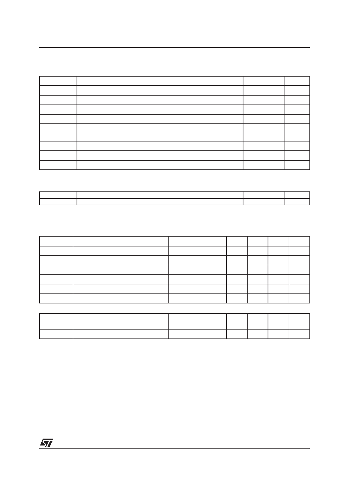
ABSOLUTE MAXIMUM RATINGS
Symbol Parameter Value Unit
SAVcc Scanning Section Analog Supply Voltage 13.5 V
VAVcc Video Section Analog Supply Voltage 13.5 V
PVcc Supply Voltage for Video Pre-Amp Section 13.5 V
Vdd Logic Section Supply Voltage 5.5 V
V
ESD
Tstg Storage Temperature -40 to 150
Tj Junction Temperature 150
Toper Operating Temperature (Device ambient) 0 to 70
ESD susceptibility HBM model 100pF & 1.5kΩ
EIAJ Norm 200pF & 0Ω
2
300
THERMAL DATA
STV2000
kV
V
o
C
o
C
o
C
Symbol Parameter Value Unit
R
TH(j-a)
Junction to Ambient Thermal Resistance (MAX) 46
SYNC INPUT
Operating Conditions (VDD= 5V, T
Symbol Parameter Test Conditions Min Typ Max Unit
HSVR Voltage on Hin Pin 44 0 5 V
MinD Min Hin pulse duration Pin 44 0.7 us
Mduty Max Hin Duty Cycle Pin 44 25 %
VSVR Voltage on Vin Pin 1 0 5 V
VSW Min Vin pulse duration Pin 1 5 us
VSD Max VinDuty Cycle Pin 1 15 %
Electrical Characteristics (VDD= 5V, T
V
INTH
RIN Horizontal & Vertical Pull-Up Resistor 200 kΩ
Horizontal & Vertical Input Logic Level Low Level
amb
=25°C)
=25°C)
amb
0.8 V
High Level 2.2
o
C/W
V
5/38
4
Page 6

STV2000
I2C READ/WRITE
Electrical Characteristics (VDD= 5V, T
Symbol Parameter Test Conditions Min Typ Max Unit
F
T
T
HIGH
V
V
V
SCL
LOW
INL
INH
ACK
Maximum Clock Frequency 100 kHz
Low Period of the SCL Clock 1.3 us
High Period of SCLClock 0.6 us
SDA & SCL Input Low Level Voltage 1.5 V
SDA & SCL Input High Level Voltage 3 V
Acknowledge Output Voltage on SDA
input with 3mA
amb
=25°C)
0.4 V
HORIZONTAL SECTION
Operating Conditions
Symbol Parameter Test Conditions Min Typ Max Unit
VCO
Ro(min) Minimum Oscillator Resistor 6 kΩ
Co(min) Minimum Oscillator Capacitor 390 pF
Fmax Maximum Oscillator Frequency 150 kHz
OUTPUT SECTION
I
HFB
I
HOUT
Electrical Characteristics (VDD= 5V, T
Symbol Parameter Test Conditions Min Typ Max Unit
SUPPLY AND REFERENCE VOLTAGES
Vcc Supply Voltage 9.5 10.5 11.5 V
Vdd Supply Voltage 4.5 5 5.5 V
Icc Supply Current 30 mA
Idd Supply Current 5 mA
V
HREF
VVREF Vertical Reference Voltage I=-2mA 7.4 8 8.6 V
I
HREF
I
VREF
Horizontal FlyBack Input Maximum
Current
Horizontal Drive Output Maximum Sink
Current
=25°C)
amb
Horizontal Reference Voltage I=-2mA 7.4 8 8.6 V
Horizontal Reference Maximum Source
Current
Vertical Reference Maximum Source
Current
5mA
15 mA
5mA
5mA
6/38
4
Page 7

STV2000
Operating Conditions
Symbol Parameter Test Conditions Min Typ Max Unit
1st PLL SECTION
V
clamp
V
VCO
A
VCO
H
PHASE
VPMIN
VPTYP
VPMAX
I
PLL1-UL
I
PLL1-L
f
O
VCO clamp Voltage range V
VCO clamp Voltage, at POR V
VCO Gain
Horizontal Phase Adjustment Range % of Horizontal Period +/-10 %
Horizontal Phase
Minimum
Typical
Maximum
PLL1 Charge Pump Current
Free Running Frequency, no input
at POR, lower clamp voltage at max.
dfo/dT Free Running Frequency Thermal Drift -150 ppm/
2nd PLL SECTION & HORIZONTAL OUTPUT SECTION
V
THFB
Jitter
Flyback Input Threshold Voltage 0.65 0.75 V
Horizontal Jitter At 60KHz 70 ppm
H
Horizontal Drive Output Duty Cycle
H
DC
(Ratio of Power TransistorOFF time to
Period)
Vphi2 Internal Clamp Level on PLL2 Filter
VSCinh
Vsat
Threshold Voltage to Stop H-Out, V-Out,
Reset ABL when Vcc<VSCinh
Horizontal Drive Output Saturation
HD
Voltage
=8V 3.0 3.8 V
HREF
=8V 3.8 V
HREF
Ro=6490Ω, Co=820pF,
dF/dV=1/11RoCo
17.1 kHz/V
SubAdd 07
X1111111
X1000000
X0000000
Unlocked
Locked
2.8
3.4
4.0
+/-140
+/-1
Ro=6490Ω, Co=820pF 65 kHz
48 %
Low Level
High Level
1.6
4.0
6.9 V
Iout=15mA 0.4 V
V
V
V
µA
mA
V
V
o
C
7/38
4
Page 8

STV2000
VERTICAL SECTION
Symbol Parameter Test Conditions Min Typ Max Unit
Electrical Characteristics (VDD= 5V, T
VERTICALRAMP SECTION
V
RBOT
V
RTOP
V
RTOPF
T
VDIS
F
FRV
ASFR Auto-Sync Frequency Range C
RAFD
R
LIN
V
POS
VOR Vertical Output Peak to Peak Voltage
I
VOUT
V
VRB
dVS
EAST/WEST FUNCTION (output is internal, can be checked at EWFB pin indirectly)
EW
DC
TDEW
EW
PARA
Voltage at Ramp Bottom Point V
Voltage at Ramp Top Point with Sync V
Voltage at Ramp Top Point without Sync V
Vertical Sawtooth Discharge Time C
Vertical Free Running Frequency
(S correction inhibited)
Ramp Amplitude Drift Versus Frequency
at Maximum Vertical Amplitude
Ramp Linearity at Vcap pin
with S Correction inhibited
Vertical Position Adjustment Voltage
with V
mean value
OUT
Vertical Output Maximum Current +/-5 mA
Vertical Ramp Filter Voltage 2 V
Max Vertical S-Correction Amplitude
S-Correction inhibited, DV/Vpp at TV/4
S-correction Maximum,
DV/Vpp at 3TV/4
DC Output Voltage with Typical VPOS
and Keystone inhibited
With external driver connected as unity
gain buffer
DC Output Voltage Thermal Drift
DC
(Non-test Parameter)
Parabola Amplitude with Max VAMP,
Typ VPOS, Keystone inhibited
amb
=25°C)
=8V 2 V
VREF
=8V 5 V
VREF
V
-
=8V
VREF
=150nF 70 µs
OSC
=150nF 100 Hz
C
OSC
=150nF 50 165 Hz
OSC
=150nF 50Hz -
C
OSC
165Hz
2.5V < VOSC < 4.5V 0.5 %
Sub-Add=09
X0000000
X1000000
X1111111 3.65
Sub-Add=08
10000000
11000000
11111111 3.5
Sub-Add 0A
0XXXXXXX
11111111
Sub-add 0C
11111111
11000000
10000000
RTOP
0.1
200 ppm/Hz
3.2
3.5
3.8
2.25
3
3.75
-4
+4
2.0 V
100 ppm/
1.0
0.5
0
3.3 V
2.5 V
V
V
V
V
V
%
%
o
C
V
V
V
8/38
4
Page 9

STV2000
Symbol Parameter Test Conditions Min Typ Max Unit
Parabola Amplitude Function of VAMP
EW
track
Control (tracking between VAMP & EW)
with Typ VPOS, Keystone, Typ EW
Amplitude.
Keystone Adjustment Capability with
KeyAdj
Typ VPOS, EW inhibited and Max
Vertical Amplitude
Intrinsic Keystone Function of VPOS
Control (tracking between VPOS and
KeyTrack
EW) with Max EW Amplitude and
Max Vertical Amplitude
A/B Ratio
B/A Ratio
INTERNAL DYNAMIC HORIZONTAL PHASE CONTROL
Side Pin Balance Parabola Amplitude
SBPpara
with Max VAMP, Typ VPOS and
Parallelogram inhibited
Side Pin Balance Parabola Amplitude
SPBtrack
function of VAMP Control (tracking between VAMP & SPB) with Max SPB,
Typ VPOS and Parallelogram inhibited
Parallelogram Adjustment Capability
ParAdj
with Max VAMP, Typ VPOS and
Max SPB
Intrinsic Parallelogram Function of
VPOS Control (tracking between VPOS
Partrack
and DHPC) with Max VAMP, Max SPB
and Parallelogram inhibited
A/B Ratio
B/A Ratio
VERTICALBREATHING COMPENSATION
VBRrng Input DC Breathing Control Range 1 10.5 V
VBRadj
Vertical Output Variation versus DC
Breathing Control
HORIZONTAL SIZECONTROL
Hsize
Hsize output DC voltage
sitting on top of EWDC=2.0V
EW OUTPUT BUFFER
Iewout EWout pin max sourcecurrent 3.0 mA
EWFB EWoutput referred DC voltage 2.0 V
Sub-address 08
10000000
11000000
11111111
Sub-address 0B
10000000
11111111
Sub-add 09
X0000000
X1111111
Sub-add 0E
11111111
10000000
Sub-add 08
10000000
11000000
11111111
Sub-add 0F
11111111
10000000
Sub-add 09
X0000000
X1111111
Vbrin>V
VREF
Vbrin=4V
sub-add 0D
X0000000
X1111111
0.2
0.2
0.52
0.52
+1.4
-1.4
0.5
0.9
1.4
+1.4
-1.4
0.52
0.52
0
-10
0
2.4
V
V
%T
%T
%T
%T
%T
%T
%T
%
%
V
V
V
pp
pp
H
H
H
H
H
H
H
V
V
9/38
4
Page 10

STV2000
Symbol Parameter Test Conditions Min Typ Max Unit
HORIZONTAL BREATHING COMPENSATION
HBRdc Breathing input DC Control Range 1 10.5 V
Horizontal size compensation, EW DC
HSC
voltage variation under full range of
0.4 V
HBRdc
VIDEO PRE-AMP SECTION
Symbol Parameter Test Conditions Min Typ Max Unit
DC Electrical Characteristics (VAVCC=PVCC= 10.5V, Tamb = 25oC)
VAV
cc
Video Section Analog Supply Voltage
PVcc Power Section Supply Voltage 9.5 10.5 11.5 V
IS Supply Current of VAVcc & PVcc 60 mA
Video Input Voltage Amplitude 0.7 1 Vpp
Typical Output Voltage Range 0.5 7 V
Output DC level (Black level) 1.5 V
V
V
V
IN
OUT
DC
AC Electrical Characteristics (VAVCC=PVCC= 10.5V, CL = 12pF, RL = 1KΩ, Tamb = 25oC)
Symbol Parameter Condition Min Typ Max Unit
AV Maximum Gain
CAR Contrast Attenuation Range
DAR Drive Attenuation Range 30 dB
GM Gain Match
BW Large Signal Bandwidth
DIS Video Output Distortion f=1MHz, V
t
R,tF
Video Output Rise and Fall Time
dVo Overshoot of output with respect to
actual output amplitude
BRT Brightness max DC level
Brightness min DC level
R
L
Equivalent Load on Video Output Tj<Tj
Tsample Hold time 100 ms
Max Contrast and Drive
2
C Gainwin = 1
I
= 0.7Vpp
V
IN
Contrast and Drive at
POR
= 0.7Vpp,
V
IN
= 4Vpp, Contrast
V
OUT
and Drive= 0.87Max
V
=0.7Vpp,
IN
= 4Vpp, Contrast
V
OUT
and Drive = 0.87Max
At -3dB
=1Vpp,
IN
= 1Vpp
V
OUT
V
= 0.7Vpp,
IN
=4Vpp,Contrast
V
OUT
and Drive=0.87Max
=5pF 5 7 %
C
LOAD
MAX
9.5 10.5 11.5 V
18 dB
30 dB
+-0.1 dB
70 MHz
0.3 %
5ns
2.5
0
1kΩ
V
V
10/38
4
Page 11

STV2000
Symbol Parameter Test Conditions Min Typ Max Unit
Thold Sample time 1 µs
= 0.7Vpp,
V
IN
= 2.5Vpp,
CT Crosstalk Between Video Channels
CUTOFF
V
CUTOFF
I
CUTOFF
CUTOFF DAC output voltage
Output sink current
Output source current 2
ABL COMPENSATION
V
OUT
Contrast and
Drive=0.7Max
f=1MHz
00000000
10000000
11111111
44 dB
0.5
2.5
4.5
100 µA
V
V
V
mA
R
G
TH
ABL
ABL
ABL
ABL Input resistor 10 kΩ
ABL minimum Attenuation
ABL maximum Attenuation
ABL latch function activation threshold
(High beam current detection)
V
=5.3V
ABL
=2.8V
V
ABL
01V
0
12
DAC
sub-add 12
VDAC I
LOAD
=100uA
00000000
01000000
01111111
0.5
2.25
4.0
IDAC Source current 1.5 2 mA
LOGIC SECTION
DC Electrical Characteristics (VAVCC=PVCC= 10.5V, Tamb = 25oC)
Symbol Parameter Condition Min Typ Max Unit
V BLANKING OUTPUT SECTION
Blanking output high voltage 7 V
VBDC
Blanking output low voltage
I2C adjustable
I
T
BLK
BLK
Output sink current 0.3 mA
Vertical blanking time
(gated with Hflyback)
SUPPLY VOLTAGE THRESHOLD
V
THPD1
V
THPD2
Supply first threshold voltage 8.5 V
Supply second threshold voltage 6.9 V
sub-add10
1X000000
1X111111
1
4.5
22 H cycle
dB
dB
V
V
V
V
V
11/38
4
Page 12

STV2000
I2C BUS ADDRESS TABLE
[0] denotes POR value, X denotes unused data bit and must be set to 0.
D8 D7 D6 D5 D4 D3 D2 D1
WRITE MODE (SLAVE ADDRESS= 8C)
Video: 1, on
00
01
02
03
04
05
06
07
08
09
0A
0B
0C
0D x
0E
0F
10
11
12
13x xxx
[0], off
[1] [0] [1] [1] [0] [1] [0] [0]
[1] [0] [1] [1] [0] [1] [0] [0]
[1] [0] [1] [1] [0] [1] [0] [0]
[0] [0] [0] [0] [1] [0] [0] [0]
[0] [0] [0] [0] [1] [0] [0] [0]
[0] [0] [0] [0] [1] [0] [0] [0]
Hout
0, off
[1], on
Vramp
0, off
[1], on
Xray
1, reset
[0]
S Select
1, on
[0], off
EW Key
0, off
[1], on
EW Select
0, off
[1], on
SPB Sel
0, off
[1], on
Parallelog
0, off
[1], on
VBDC
1, on
[0], off
POR
[0], off
1, reset
[1] [0] [1] [1] [0] [1] [0]
Cut off 1
Cut off 2
Cut off 3
Horizontal Phase Adjustment
[1] [0] [0] [0] [0] [0] [0]
Vertical Ramp Amplitude Adjustment
[1] [0] [0] [0] [0] [0] [0]
Vertical Position Adjustment
[1] [0] [0] [0] [0] [0] [0]
[1] [0] [0] [0] [0] [0] [0]
[1] [0] [0] [0] [0] [0] [0]
[1] [0] [0] [0] [0] [0] [0]
[1] [0] [0] [0] [0] [0] [0]
[1] [0] [0] [0] [0] [0] [0]
[1] [0] [0] [0] [0] [0] [0]
Gainwin
[0], 1X
1, 1.5X
Powsav
1, on
[0], off
[1] [0] [0] [0] [0] [0] [0]
[1] [1] [1] [1] [1] [1]
[1] [0] [1] [1] [0] [1]
Contrast
Drive 1
Drive 2
Drive 3
S Correction
Keystone
EW Amplitude
Horizontal Amplitude
Side Pin Balance
Parallelogram
Vertical Blanking DC level
Brightness
DAC
PLL1 filter voltage clamp (FVC)
[0] [0] [0] [0]
12/38
4
Page 13

D8 D7 D6 D5 D4 D3 D2 D1
READ MODE (SLAVE ADDRESS = 8D)
Hlock
0, lock
[1], unlock
Xray
1, on
[0], off
Figure 1. EW Output Referred Voltage
A
EW
DC
Figure 2. Dynamic Horizontal Phase Control Output
EW
STV2000
B
PARA
EW
A
DHPC
DC
SPB
Figure 3. Keystone Effect on EW Output (PCC Inhibited)
PARA
PARA
B
Keyadj
13/38
4
Page 14

STV2000
TYPICAL OUTPUT WAVEFORMS
Function
Vertical Size
Vertical
Position
Vertical
S
Linearity
Sub
Address
Pin Byte Specification Effect on Screen
2.25 V
10000000
3.75 V
11111111
x0000000
x1000000
x1111111
V
V
V
OUTDC
OUTDC
OUTDC
= 3.2 V
= 3.5 V
= 3.8 V
00000000
Inhibited
11111111
V
PP
Keystone
EW
Pin Cushion
14/38
EW
Inhibited
10000000
11111111
EW
Inhibited
10000000
11111111
2.0V
2.0V
2.0 V
2.0 V
0.2Vpp
0.2Vpp
1.0 V
4
Page 15

STV2000
Function
H Amplitude
H Phase
Side Pin
Ballance
Control
Sub
Address
Pin Byte Specification Effect on Screen
10000000
11111111
5V
00000000
01111111
5V
Parallelogram
Inhibited
10000000
11111111
3.7 V
1.4%
1.4%
3.7 V
Parallelo-
gram
Control
SPB
Inhibited
10000000
11111111
3.7 V
3.7 V
1.4%
1.4%
15/38
4
Page 16

Contrast Register (Video IN = 0.5VPP, Drive at maximum, I2C Gainwin=1)
Hex b7 b6 b5 b4 b3 b2 b1 b0 Vpp G(dB) POR
000000000 -
000000010.015-30
000000100.031-24
000001000.062-18
000010000.125-12
0 0 0 1 0 0 0 0 0.25 -6
001000000.50
01000000212
010110102.81215 X
01111111418
Brightness Register (Drive at maximum)
Hexb5b4b3b2b1b0VppPOR
0000000
0000010.010
0000100.020
0001000.040
0010000.08
0100000.16
1000000.32
0000000.64
0000001.28
1011011.8X
1111112.56
Drive1, Drive2, Drive3 Registers (Video IN = 0.5VPP, Contrast at maximum, I
Hex b7 b6 b5 b4 b3 b2 b1 b0 Vpp G(dB) POR
00000000000 01 0 0 0 0 0 0 0 1 0.015 -30
02 0 0 0 0 0 0 1 0 0.031 -24
04 0 0 0 0 0 1 0 0 0.062 -18
08 0 0 0 0 1 0 0 0 0.125 -12
10 0 0 0 1 0 0 0 0 0.25 -6
20001000000.50
40010000001 6
8010000000212
B4101101002.81215 X
FF11111111418
2
C Gainwin=1)
16/38
5
Page 17

STV2000
Cutoff1, Cutoff2, Cutoff3 Output values
Hexb7b6b5b4b3b2b1b0FBpinPOR
00000000000.5
0100000001
0200000010
0400000100
08000010000.625 X
1000010000
2000100000
4001000000
8010000000
B410110100
FF111111114.5
DAC Output DC voltage
Hex b6 b5 b4 b3 b2 b1 b0 Output dc POR
00000000.5
0000001
0000010
0000100
0001000
0010000
0100000
1000000
10000002.25 X
0110100
11111114.0
Vertical Blanking Output DC voltage
Hex b5 b4 b3 b2 b1 b0 Output dc POR
0000001.0
000001
000010
000100
001000
010000
100000
000000
000000
110100
1111114.5X
17/38
5
Page 18

STV2000
OPERATING DESCRIPTION
A SCANNING PART
1. GENERAL CONSIDERATIONS
1.1 Power Supply
Typical power supply voltages are 10.5 V for the
Deflection and Preamplifier sections (SAVCC,
VAVCCand PVCC) and 5.0 V for the logic section
(Vdd). Optimumoperation is obtainedbetween 9.5
and 11.5 for VCC, and between 4.5 and 5.5 V for
VDD.
VCCis monitored during the transient phase when
switched either on or off, to avoid erratic operation
of the circuit. If VCCis inferior to 6.9 V typ., the circuit outputs are inhibited. Similarly, before V
reaches 4 V, all the I2C registers are reset to their
default value (see I2C Control Table).
The circuit is internally supplied by several voltage
references (typ. value: 8 V) to ensure a good power supply rejection. Two of these voltage references are externally accessible respectively for the
vertical and horizontal parts. They can be used to
bias external circuitry if I
To minimize the noiseand consequently the ”jitter”
on vertical and horizontal output signals, the reference voltages must be filtered by external capacitors connected to the ground.
1.2 I2C Control
STV2000 belongs to the I2C-controlled device
family. Each adjustment can be made via the I2C
Interface, insteadof being controlled by DC voltages on dedicated control pins. The I2C bus is a serial bus with a clock and a data input. General
function and bus protocol are specified in the
Philips-bus data sheets. The interface (Data and
Clock) is TTL-compatible. Spikes up to 50 ns are
filtered by an integrator and the maximum clock
speed is limited to 100 kHz.
The data line (SDA) can be used bidirectionally. In
read mode, the IC sends reply information (1 byte)
to the micro-processor.
The bus protocol prescribes a full-byte transmission in all cases. The first byte after the start condition is used to transmit the IC address (hexa 8C
for write, 8D for read).
All bytes are sent MSB bit first and the write data
transfer is closed by a stop.
is inferior to 5 mA.
LOAD
DD
1.3 Write Mode
In write mode, the second byte contains the subaddress of the selected function to adjust (or controls to effect)and the third byte the corresponding
data byte. More than one data byte can be sent to
the IC. If after the third byte no stop or start condition is detected, the circuit automatically increments the momentary subaddress in the subaddress counter (auto-increment mode) by one.
Thus it is possible to immediately transmit the following data bytes without sending the IC address
or subaddress. This can be useful for reinitializing
all the controls very quickly (flash manner). This
procedure is ended with a stop condition.
There are 19 adjustment capabilitiesfor the circuit:
3 for the horizontal part, 3 for the vertical, 3 for the
E/W correction, 2 for the dynamic horizontal phase
control, 7 for the preamplifier and 1 for the blanking DC. 14 bits are also dedicated to several controls (ON/OFF).
1.4 Read Mode
In the read mode the second byte transmitsthe reply information. The reply byte contains the horizontal and vertical lock/unlock status, the XRAY
activation status. A stop condition always stops all
the activities of the bus decoder and switches both
the data and clock line (SDA and SCL) to high impedance. See I2C subaddress and control tables.
1.5 Sync Processor
The internal sync processor allows the device to
receive separate horizontal & vertical TTL-compatible sync signals.
1.6 IC Status
The IC informs the MCU about both the 1st horizontal PLL (locked or not) and the XRAY protection (activated or not). The XRAY internal latch is
reset either directly via the I2C interface or by decreasing the VCCsupply.
1.7 Sync Inputs
Both HIN and VIN inputs are TTL compatible triggers with hysterisis to avoid erratic detection. Both
inputs include a pull-up resistor connected to VDD.
Synchro pulses must be positive.
18/38
6
Page 19

STV2000
OPERATINGDESCRIPTION (continued)
1.8 Sync Processor Output
The sync processor indicates whether 1st PLL is locked to an incoming horizontal sync or not. This is indicated on the D8 bit of the status register . PLL1 level is low when locked.
2. HORIZONTAL PART
2.1 Internal Input Conditions
A digital signal (horizontal sync pulse) is sent by
the sync processor to the horizontal input. It must
be positive (see Figure 4).
Synchronization occurs on the leading edge of the
internal sync signal.
The minimum value of Z is 0.7 µs.
Vertical synchro extraction is not allowed.
Figure 4.
Z
T
2.2 PLL1
The PLL1 consists of a phase comparator, an external filter and a voltage-controlled oscillator
(VCO). The phase comparator is a ”phase frequency” type designed in CMOS technology. This
kind of phase detector avoids locking on wrong
Figure 6. Block Diagram
frequencies. It is followed by a ”charge pump”,
composed of two current sources: sunk and
sourced (typically I =1mA when locked and
I = 140 µA when unlocked). This difference between lock/unlock allows smooth catching of the
horizontal frequency by PLL1. This effect is reinforced by an internal original slow down system
when PLL1is locked, preventing the horizontal frequency from changing too quickly. The dynamic
behaviour of PLL1 is fixed by an external filter
which integrates the current of the charge pump. A
”CRC” filter is generally used (see Figure 5).
Figure 5.
PLL1F
40
1.8kΩ
10nF
4.7µF
H/HVIN
44
LOCKDET
COMP1
High
Low
Lock/Unlock
Status
CHARGE
PUMP
39 Filter
PHASE
ADJUST
PLL1F R0 C0
40 42 41
VCO
OSC
2
C
I
HPOS
Adj.
FC1
43
19/38
6
Page 20

STV2000
OPERATINGDESCRIPTION (continued)
Figure 7. Details of VCO
I
0
PLL1F
(Loop Filter)
(1.4V<V7<6.4V)
40
42
4I
R0
I
0
2
0
41
6.4V
1.6V
C0
6.4V
1.6V
0 0.875T
RS
FLIP FLOP
T
H
H
The VCO uses an external RC network. It delivers
a linear sawtooth resulting from the capacitor
charge and discharge . The current is proportional
to the one in the resistor. Typical thresholds for the
sawtooth are 1.6 V and 6.4 V.
The VCO control voltage varies between 3.0 V
and 3.8V (see Figure 7). This VCO frequency
range is very small. The small effective frequency
is dueto clamp intervention on the lowest filter value. The PLL1F filter voltage is set by a 4-bit DAC
with a voltagerange of 3.0 to 3.8 V.
The sync frequency must always be higher than
the freerunning frequency. For example, whenusing a 60 kHz synchro range, the suggested free
running frequency is 56 kHz.
Figure 8. PLL1 Timing Diagram
HO
SC
Sawtooth 7/8 TH
Phase REF1
1/8 TH
PLL1 ensures the coincidence between the leading edge of the sync signal and a phase reference
resulting from the comparison of:
– the VCO sawtooth
– an internal DC voltage I2C adjustable within the
range of 2.9V to 4.2V (corresponding to ±10%)
(see Figure 8).
A Lock/Unlock identification block, also included,
detects in real time whether PLL1 is locked on the
incoming horizontal sync signal or not.
The lock/unlock information is available through
the I2C read.
The FC1 Pin (Pin 43) is used for decoupling the internal 6.4 V reference by a capacitor.
6.4V
3.4V (Reference for H Position)
Vb
(2.8V<Vb<4.2V)
1.6V
HSynchro
Phase REF1 is obtained by comparison between the sawtooth and a DC voltage adjustable between 2.9 V and 4.2 V.
The PLL1 ensures the exact coincidence between the signal phase REF and HSYNC.
A ±10% T
20/38
phase adjustment is possible around the 3.5V point.
H
6
Page 21

OPERATINGDESCRIPTION (continued)
STV2000
2.3 PLL2
PLL2 ensures a constant position of the shaped
flyback signal in comparison with the sawtooth of
the VCO, taking into account the saturation time
Ts (see Figure 9).
Figure 9. PLL2 Timing Diagram
H Osc
Sawtooth
7/8T
H
1/8T
H
6.4V
4.0V
1.6V
Flyback
Internally
Shaped
Flyback
H Drive
Ts
duction period of the horizontal scanning transistor.
The maximum storage time (Ts Max.) is :
0.44TH-T
Typically, T
FLY
FLY/TH
/2).
corresponds to around 20 %
which means that Ts max represents approxim
tively 34 % of TH.
2.4 Output Section
The H-drive signal is sent to the output through a
shaping stage which also controls the fixed Hdrive duty cycle (see Figure 9). In order to secure
the scanning power part operation, the output is inhibited in the following cases :
-when VCCis too low,
-when the ABL protection is activated,
-during the Horizontal flyback,
-when the HDrive I2C bit control is off.
The output stage consists of a NPN bipolar tran-
sistor. Only the collector is accessible
(see Figure 11).
Figure 11.
V
CC
Duty Cycle
The phase comparator of PLL2 (phase type comparator) is followed by a charge pump (typical output current: 0.5 mA).
The flyback input consists of an NPN transistor.
This input must be current driven. The maximum
recommended input current is 5 mA
(see Figure 10).
Figure 10. Flyback Input Electrical Diagram
400Ω
HFLY 36
20kΩ
GND 0V
Q1
The duty cycle is fixed at 48%. For a safestart-up
operation, the initial duty cycle (after power-on reset) is 85% in order to avoid having too long a con-
Hout
34
This output stage is intended for ”reverse” base
control, where setting the output NPN in off-state
will control the power scanning transistor in offstate.
The maximum output current is 15 mA, and the
corresponding voltage drop of the output V
0.4 V Max.
CEsat
Obviously, the power scanning transistor cannot
be directly driven by the integrated circuit. An interface either bipolar or MOS type has to be added
between the circuitand the power transistor.
is
21/38
6
Page 22

STV2000
OPERATINGDESCRIPTION (continued)
2.5 X-RAYProtection
X-Ray protection is activated when the ABL input (1 V on Pin 20) is at a low level. It inhibits both H-Drive,
and Vout while Video goes into off-mode.
This activation is internally delayed by 2 lines to avoid erratic detection (short parasitics).
This protection is latched; it may be reset eitherby switching VCCoff or by I2C (see Figure 12).
Figure 12. Safety Functions Block Diagram
VCCChecking
V
+1V
CC
VSCinh
XRAYProtection
+
20
ABL
VCCoff or I2C Reset
Horizontal Flyback
0.7V
3. VERTICAL PART
3.1 Function
When the synchronization pulse is not present, an
internal current source sets the free running frequency. For an external capacitor, C
OSC
= 150nF,
the typical free running frequency is 100Hz.
The typical freerunning frequency can be calculat-
ed according to:
fo(Hz) = 1.5.10
-5 .
C
1
OSC
A positive TTL level pulse applied on Pin 1(Vin) is
used to synchronize the ramp in the range [fmin,
fmax] (see Figure 13). This frequency range depends on the external capacitor connected on Pin
5. A 150nF (± 5%) capacitor is recommended for
50 Hz to 165 Hz applications.
The typical maximum and minimum frequency, at
25oC and without any correction (S correction),
I2C Drive on/off
HORIZONTAL
OUTPUT
INHIBITION
I2C Ramp on/off
S
Q
R
VERTICAL
OUTPUT
INHIBITION
Video-off
can be calculated as follows:
f(Max.) = 3.5 x foand f(Min.) = 0.33 x f
o
When an S correction is applied, these values are
slightly modified.
With a synchronization pulse, the internal oscillator is synchonized immediately but its amplitude
changes. An internal correction then adjusts it in
less than half asecond. The ramp top value (Pin 5)
is sampled on the AGC capacitor (Pin 3) at each
clock pulse. A transconductance amplifier modifies the charge current of the capacitor so as to
make the amplitude constant again. We recommend using an AGC capacitor with a low leakage
current. A value lower than 100nA is mandatory.
A good level of stability forthe internal closed loop
is obtained by a 470nF ± 5% capacitor value on
Pin 3 (VAGC).
VRB (Pin 8) is used for decoupling the internal 2V
reference voltage by a capacitor.
22/38
6
Page 23

OPERATINGDESCRIPTION (continued)
STV2000
3.2 I2C Control Adjustments
S correction shapes can then be added to this
ramp. This frequency-independent S correction is
generated internally. Its amplitudes is adjustable
via the I2C. Scorrection can beinhibited by applying the selected bits.
Finally, the amplitude of the S corrected ramp is
adjustable via the vertical ramp amplitude control
register.The adjusted ramp is available on Pin 6
(V
) to drive an external power stage.
OUT
Figure 13. AGC Loop Block Diagram
DISCH.
VSYNCIN
1
SYNCHRO OSCILL ATOR
The gain of this stage can be adjusted (± 25%) depending on its register value.
The mean value of this ramp is driven by its own
I2C register (vertical position) with :
VPOS = 7/16 x V
Usually V
is sent through a resistive divider to
OUT
REF-V
= ± 300 mV.
the inverting input of the booster. Since VPOS derives from V
inverting input of the booster should also derive
from V
REF-V
,the bias voltage sent tothenon-
REF-V
to optimize the accuracy
(see Figure 13).
TRANSCONDUCTANCE
CHARGECURRENT
5
OSC
CAP
Vlow
Sawth
Disch
VERTAMP
SUB08/7bits
VPOSITION
SUB09/7bits
SAMPLING
.
AMPLIFIER
REF
3
SAMPLING
CAPACITANCE
SCORRECTION
VSAMP
SUB07/7bits
7
BREATH
6VOUT
3.3 Basic Equations
As a first approximation, the amplitude of the ramp
on Pin 6 (VOUT) is calculated as follows:
V
- VPOS = (V
OUT
OSC-VDCMID
) x (1 + 0.25 (V
AMP
))
where :
V
DCMID
=7/16xV
(middle value of the ramp on
REF
Pin 5, typically 3.6V)
V
OSC=V5
V
AMP
(ramp with fixed amplitude)
= -1 as minimum vertical amplitude register
value and +1 as maximum value.
VPOS is calculated according to:
VPOS = V
DCMID
+ (0.4x VP)
where VP= -1 and +1 as respectively minimum
and maximum vertical position register value.
The current available on Pin 5 is:
I
OSC
where
C
OSC
3
=xV
8
REFxCOSC
xf
= capacitor connected on Pin 5
f = synchronization frequency.
23/38
6
Page 24

STV2000
OPERATINGDESCRIPTION (continued)
3.4 Geometric Corrections
The principle is represented in Figure 14.
Starting from thevertical ramp, a parabola-shaped
current is generated for E/W correction (also
known as Pin Cushion correction), dynamic horizontal phase control correction.
The parabola generator consists of an analog multiplier, the output current of which is equal to :
∆I=kx(V
where V
- V
OUT
is the vertical output ramp (typically
OUT
between 2 and 5 V) and V
(for V
= 8.2V). The VOUT sawtooth is typical-
REF-V
DCMID
)
2
DCMID
is 3.6 V
ly centered on 3.6 V. By changing the vertical position, the sawtooth shifts by ±0.4 V.
The ”geometry tracking” feature ensures a correct
screen geometry for any end user adjustment. It
generates non-symmetric parabola dependent on
the vertical position.
Due to the large output stage voltage range (E/W
Pin Cushion, Keystone), the combination of the
tracking function, maximum vertical amplitude,
maximum or minimum vertical position and maxi-
Figure 14. Geometric Corrections Principle
mum gain on the DAC control may lead to output
stage saturation. This must be avoided by limiting
the output voltage with appropriate I2C register
values. For the E/W part and the dynamic horizontal phase control part, a sawtooth-shaped differential current in the following form is generated:
∆I’= k’.(V
OUT
- V
DCMID
).
Then ∆I and ∆I’ are added and converted into voltage for the E/W part.
Each of the two E/W components or the two dynamic horizontal phase control components may
be inhibited by their own I2C select bit.
Internal EW correction voltage is not available directly on the output pin. The EW correction is obtained with the feedback voltage (Pin 27: EWBin)
which generates a modulating current in the diode
(Pin 28). In addition, the horizontal width is I2Ccontrolled.
The dynamic horizontal phase control drives the
H-position internally, moving theHFLY position on
the horizontal sawtooth in the range of ± 2.8 %T
both for side pin balance and parallelogram.
H
3.5 E/W
EWOUT = EWDC+K1(V
OUT
- V
DCMID
) +K2 (V
OUT
- V
DCMID
2
)
K1 is adjustable via the keystone I2C register. K2 is adjustable via the E/W amplitude I2C register.
24/38
6
Page 25

OPERATINGDESCRIPTION (continued)
3.6 Dynamic Horizontal Phase Control
I
OUT
=K4(V
OUT
- V
DCMID
) + K5 (V
OUT
- V
DCMID
2
)
K4 is adjustable via the parallelogram I2C register.
K5 is adjustable via the side pin balance I2C register.
3.7 Horizontal Breathing
Horizontal breathing compensation is performed
through the EW stage with the Voltage-Current
Converter. This DC-controlled input provides the
required horizontal width corrections to offset
width changes arising from EHT variations.
B PRE-AMPLIFIER PART
1. GENERAL CONSIDERATIONS
STV2000
3.8 Vertical Breathing
Vertical breathing compensation is performed
through the gain modulation of the vertical ramp.
This DC-controlled input provides the vertical
height corrections required to offset height changes arising from EHT variations.
1.1 Input Stage
The R, G and B signals must be supplied to the
three inputs through coupling capacitors (100nF).
The maximum input peak-to-peak video amplitude
is 1 V.
Figure 15. .
HSYNC
BPCP
Internal pulse width is fixed at 1µs
In both cases, BPCP width is fixed.
1.2 Contrast Adjustment (7 bits)
The contrast adjustment is made bysimultaneously controlling the gain of three internal variable
gain amplifiers through the I2C bus interface. The
contrast adjustment allows covering a range higher than 40 dB. This adjustment is refreshed during
the vertical retrace time.
1.3 ABL Control
The STV2000 has an ABL input (automatic beam
limitation) to attenuate RGB video signals according to beam intensity.
The inputstage includes a clamping function. This
clamp uses the input serial capacitor as ”memory
capacitor” and is gated by an internally generated
”Back-Porch-Clamping-Pulse (BPCP)”.
The BPCP is synchronized on the second edge of
the horizontal pulse HIN inputs on Pin 44.
The operating range is typically 2.5 V, from 5.3V
to 2.0 V. A typical 12 dB Max. attenuation is applied to the signal whatever the current gain. Refer
to Figure 16 for ABL input attenuation range.
In the case of software control, the ABL input must
be pulled to AVCCthrough a resistor to limit power
consumption.
ABL input voltage must not exceed VAVCC. Input
resistor is 10kΩ.
25/38
6
Page 26

STV2000
OPERATINGDESCRIPTION (continued)
Figure 16.
Attenuation (dB)
2
0
-2
-4
-6
-8
-10
-12
-14
123456789
V
(V)
IN
1.4 Brightness Adjustment (6 bits)
As with contrast adjustment, brightness is controlled by I2C.
The brightness function consists of adding the
same DC offset to the three R, G, B signals after
contrast amplification. This DC-Offset is present
only outside the blanking pulse (see Figure 18).
The DC output level is forced to ”INFRA-BLACK”
level (VDC) during the blanking pulse.
1.5 Drive Adjustment (3 x 8 bits)
To adjust the white balance, the device offers the
possibility of separately adjusting the overall gain
of each complete video channel. Each channel
gain is controlled by I2C (8 bits each). The very
large drive adjustment range (48dB) allows different standard or custom color temperatures.
The drive adjustment is also used to adjust the
output voltages at the optimum amplitude to drive
the C.R.T drivers, keeping the whole contrastcontrol for end-users only. The drive adjustment is
made after the contrast and brightness so that the
white balance remains correct when BRT is adjusted.
1.6 Output Stage
The three output stages (see Figure 17) incorporate three functions:
• The blanking stage: when the internal
generated blanking pulse is high, the three
outputs are switched to a voltage which is
400 mV lower than the BLACK level. The
black level is the output voltage with minimum
brightness when the input signal video
amplitude is equal to ”0”.
• The output stage itself: a large bandwidth
output amplifier which can deliver up to 5V
PP
on the three outputs (for 0.7 V video signal on
the inputs).
• The output CLAMP: the IC also incorporates
three internal output clamps (sample and hold
system) used for the DC to shift the three
output signals. The DC output voltage is fixed
at 1.5 V.
The overall waveforms of the output signal according to the different adjustments are shown in
Figure 18.and Figure 19.
Figure 17.
26/38
6
Cut-off
DAC
8 bits
S/H
1.5V
10
11
Vout
Cut-off
CRTDriver
STV2000
Page 27

OPERATINGDESCRIPTION (continued)
Figure 18. Waveforms VOUT,BRT, CONT
HSYNC
BPCP
BLK
Video IN
V
OUT1,VOUT2,VOUT3
(4)
V
CONT
STV2000
(3)
V
BRT
(2)
V
BLACK
(1)
V
DC
Note : 1. VDC= 1.5V
2. V
BLACK=VDC
3. V
BRT=VBLACK
4. V
CONT=VBRT
+ 0.4V
+ BRT (with BRT = 0 to 2.5V)
+ CONT with CONT = k x video (CONT = 5VPPmax. for VIN= 0.7VPP)
Figure 19. Waveforms (DRIVE adjustment)
HSYNC
BPCP
BLK
Video IN
,
V
OUT1VOUT2
, V
OUT3
CONT
BRT
0.4V fixed
V
CONT
V
BRT
V
BLACK
V
DC
twoexamples of
driveadjustment
(1)
Note : 1. Driveadjustment modifiesthe followingvoltages : V
Driveadjustment does not modify the followingvoltages : V
DC
.
andV
CONT,VBRT
.
BLACK
.
27/38
6
Page 28

STV2000
OPERATINGDESCRIPTION (continued)
1.7 Cutoff DAC Output
Three Cutoff DACs (8 bits) with output buffers are
incorporated to drive the external cutoff circuit.
Output voltage range is from 0.5 V to 4.5 V.
1.8 Blanking Generator
A vertical blanking pulse is generated
(see Figure 20). The output level is a positive going pulse of 8V. The vertical blanking is started by
the vertical sync pulse and the duration is determined by counting 22horizontal periods. If there is
Figure 20. VBDC (Pin 24) Output Voltage Waveform
22Hlines
DClevelcontrolledby
6-bit DAC
1.9 DAC Output
This is a 7-bit DAC with 1 output pin. An output
buffer is used to enhance load capability with an
Imax(source) of 2 mA.
no vertical sync pulse the vertical blanking start
coincides with the beginning of the vertical capacitor discharge time.
The blanking output generates a superimposed
variable DC voltage. The 6-bit adjustment range is
1 V to 4.5 V. This is used to allow brightness control through G1. Additionally, this pin is used for
spot killer suppression. The 0.8 V of Vcc threshold
will trigger the output into a high level state resulting from the Vcc decay.
8V
4.5V
1.0V
Table1: Logic Table
Conditions Hout Vout Video-off Low Power
at 0 to 6.9 V (PD2 mode) no no video-off NA (1)
V
cc
at 6.9 V to 8.5 V (PD1 mode) yes yes video-off NA(1)
V
cc
2
C DPMS bit=1, (default=0) no no video-off yes
I
Hlock/unlock detection = unlock yes yes video-off no
Video ABL input pin < 1 V no no video-off no
5VPORorI
2
C Houton/off, (default=1=on) on/off yes on/off no
I
2
C Vout on/off, (default=1=on) yes on/off on/off no
I
2
C Video on/off, (default=0=video-off) yes yes on/off no
I
at >8.5 V yes yes video-on (2) NA (1)
V
cc
at >8.5 V, I2C video=1=on yes yes video-on (2) no
V
cc
Note 1 NA= Not applicable.
Note 2 I
2
C POR=1, (default=0) yes yes video-off no
2
C video=on will be reset by I2CDPMS/Low Vcc.
28/38
6
Page 29

OPERATINGDESCRIPTION (continued)
C STAND-BY MODE AND PROTECTIONS
1. GENERAL CONSIDERATIONS
STV2000
1.1 POR (Power On Reset) - Subadress 11- D8
POR is activated on 5 V with default values for
each adjustment and in addition video off (see
1.3). It can be activated via the I2C command.
1.2 Supply Voltage Threshold.
Two built-in thresholds (see figure 21) are used to
enter the following modes:
• PDI mode:
– Activated for Vcc < 8.5V
– Video off (see 1.13)
• PD2 mode:
– Activated for Vcc < 6.9V
– Video off (see 1.13)
–H
1.3 Video Off (I2C control) - Subadress 00 - D8
Activates blanking of the 3 video output stages.
During this time the outputs are switched to
ground level, regardless of the presence of Hsync
or Hflyback. Activation time is inferior to 1µs.
OUT
and V
OUT
disabled
This also activates the blanking output generating
a positive going signal at pin 24 as long as “video
off” is activated.
1.4 Vertical Output Off
This command will switch off output VAMP. The
vertical output swing is reduced to 0V.
During power saver mode, the total vertical section
is disabled.
1.5 Power Saver On - Subadress 11 - D7
This I2C command activates the PD1 and PD2
mode regardless of the scanning Vcc value. Internal scanning and pre-amp voltage are off. During
“power saver” mode, the device power consumption will be reduced to below 20mA for all supply
pins. Vdd, I2C interface and DAC data are not affected by this command.
1.6 X-Ray, Set Operation - Subadress 09 - D8
When ABL voltage is below 1 V threshold, Xray
latch will be activated. This I2C command will reset
the Xray latch. Activation time below 100ms.
29/38
Page 30

STV2000
INTERNAL SCHEMATICS
Figure 21.
Figure 22.
Vref
1+
44
2
V
DD
SAV
CC
200Ω
Ω
200k
22k
Figure 24.
SAV
CC
4
Vgnd
Figure 25.
SAV
CC
5
VCAP
Ω
Figure 23.
VAGCCAP 3
30/38
7
SAV
CC
Figure 26.
SAV
VOUT 6
CC
Page 31

INTERNAL SCHEMATICS (continued)
STV2000
Figure 27.
BREATH
V
Figure 28.
VAV
Figure 30.
VAV
CC
IN
Agnd
Agnd
7
SAV
CC
Pins
19
21
23
Figure 31.
10k
Internal
5V
Ω
VAV
CC
CC
9
12V
BIPSWITCH
20
Figure 29.
PV
Pgnd
CC
AGND
VAV
Agnd
CC
Pins 10, 13, 16
Figure 32.
Pin 11
14
17
VAV
Agnd
Agnd
CC
10k
Ω
31/38
7
Page 32

STV2000
INTERNAL SCHEMATICS (continued)
Figure 33.
Agnd
Figure 34.
12
Pgnd
15
VAV
CC
Figure 36.
DAC
Figure 37.
VBDC
VAV
24
VAV
22
CC
AGND
CC
50
Ω
Figure 35.
32/38
7
PV
VAV
CC
CC
18
Figure 38.
HBreath
SAV
26
CC
60K
Vref
Page 33

INTERNAL SCHEMATICS (continued)
STV2000
Figure 39.
EWFB
Figure 40.
EWout
SAV
SAV
27
28
CC
CC
10k
1.5k
Vref
Vref
Figure 42.
SDA
Figure 43.
SCL
30
31
5V
5V
10K
10k
V
DD
V
DD
Figure 41.
Figure 44.
V
29
DD
5V
BIPSWITCH
SAV
CC
32
12V
BIPSWITCH
33/38
7
Page 34

STV2000
INTERNAL SCHEMATICS (continued)
Figure 45.
Figure 46.
Lgnd
HOUT
34
33
SAV
CC
Figure 48.
HFLY
Figure 49.
SAV
36
Hgnd
CC
37
Href
35
Figure 47.
SAV
Href
34/38
7
cc
35
22kΩ
Figure 50.
38PLL2C
SAV
CC
Href
Page 35

INTERNAL SCHEMATICS (continued)
STV2000
Figure 51.
Figure 52.
PLL1F
SAV
40
CC
SAV
39Filter
CC
Href
Href
Figure 54.
Figure 55.
FC1
SAV
43
SAV
42
CC
CC
Href
1K
_
3
4K
_
3
Href
35
Figure 53.
SAV
41
CC
Href
35
Figure 56.
VRB
SAV
CC
Vref
R1
8
R2
35/38
7
Page 36

STV2000
Figure 57. STV2000 Demonstration Board Schematics
Vcc
47K
C11
100n10u
C10
MC14528
C12
47K
R37
Vcc
HFLY
R38
16
VCC
TA1
1
47p
C9
47p
TB1
TA2
2
Delay
Width
14
TB2
CDA
3
Vcc
R16 10K
13
CDB
1A
4
121511
1B
N1A
5
Vcc
N1B
QA
6
10
QB
NQA
7
9
NQB
GND
8
R15 10K
C7 33p
Vcc
C6 10u
R13 1K
Hout
D1 1N4148
R12 560
R17
Vcc
5V
SDA
SCL
GND
C5
R11 100
C4
22p
22p
+5V
R8 4K7
R9 4K7
R10 100
EW
1K
BD677
C8 33p
R14 10K
C37
C36
4u7
HIN
1K8
HREF
47u
100n
22n
C35
C32
820p
6490
100n
C33
R36
VIN
C34
10n
C31
C30
R35
2K
100u
C21
OUT2
R1 10K
R2 1K
R4 1K
R6 10K
47
R20
47
R21
R22
47
100n
C22
OUT3
CUTOFF2
R23
75
R24
R25
L1
10uH
CUTOFF3
R3 10K
R5 10K
IN3
IN1 IN2
75 75
Vcc
C3
R18 25K
23
IN3
DAC
IN2
ABLIN
IN1
PVCC
CUTOFF3
OUT3
PGND
CUTOFF2
OUT2
CUTOFF1
AGND
11
100u
100n
200p
Vcc
100n
C17
R19
DAC
2221201918171615141312
C24
C23
OUT1
100n
C19
100n
C20
CUTOFF1
+5V
Vcc
100u
C16
C15
100n
31
32
33
SCL
LGND
HREF
SAVCC
HFLY
HGND
PLL2C
44 43 42 41 40 39 38 37 36 35 34
Vcc
C0
R0
FC1
HIN HOUT
VIN
1
100n
C28
R32
FILTER
PLL1F
2
47u
C29
1K
VREF
470n
C27
VAGCCAP
3
R33
1u
30
SDA
VGND
4
10K
C14
100u
C13
100n
28
29
VDD
EWOUT
STV2000
VCAP
VOUT
5
6
150n
C26
R31 12K
VOUT
27
EWFBIN
VBRTHIN
7
R31 10K
26
HBRTH
VRB
8
1u
C39
C25
100n
24
25
NC
VBDC
VAVCC
OUT1
9
10
L3 10uH
Vcc
36/38
Page 37

PACKAGE MECHANICAL DATA
44-Pin Thin Quad Flat Package
STV2000
Dimensions
D
D1
D3
33
34
44
23
22
E3
12
PIN1
IDENTIFICATION
1
11
e
L1
L
Millimeters Inches
Min. Typ. Max. Min. Typ. Max.
0.10m
m
.004
EE1
K
A
A2
A1
b
c
A 1.60 0.063
A1 0.05 0.15 0.002 0.006
A2 1.35 1.40 1.45 0.053 0.055 0.057
b 0.30 0.37 0.45 0.012 0.015 0.018
c 0.09 0.20 0.004 0.008
D 12.00 0.472
D1 10.00 0.394
D3 8.00 0.315
E 12.00 0.472
E1 10.00 0.394
E3 8.00 0.315
e 0.80 0.031
K0°3.5° 7°
L 0.45 0.60 0.75 0.018 0.024 0.030
L1 1.00 0.039
Number of Pins
N44
37/38
8
Page 38

STV2000
Information furnished is believed to be accurate and reliable. However, STMicroelectronics assumes no
responsibility for the consequences of use of such information nor for any infringement of patents or other
rights ofthird parties which may result from its use. No license is granted by implication or otherwise under any
patent or patent rights of STMicroelectronics. Specifications mentioned in this publication are subject tochange
without notice. This publication supersedes and replaces all information previously supplied.
STMicroelectronics products are not authorized for use as critical components in life support devices or
systems without the express written approval of STMicroelectronics.
The ST logo is a registered trademark of STMicroelectronics
2000 STMicroelectronics - All Rights Reserved.
Purchase of I
components in an I
2
C Components bySTMicroelectronics conveys a license under the Philips I2C Patent. Rights to use these
2
C system is granted provided that the system conforms to the I2C Standard Specification as defined
by Philips.
STMicroelectronics Group of Companies
Australia - Brazil - China -Finland - France - Germany -Hong Kong - India - Italy - Japan - Malaysia - Malta - Morocco -
Singapore - Spain - Sweden - Switzerland - United Kingdom - U.S.A.
http://www.st.com
38/38
 Loading...