

Page 1
STV0196B
QPSK/BPSK DEMODULATOR AND FEC IC
FRONT-END INTERFACE
.
I AND Q6 BITSDIGITALINPUTS AT2Fs
.
QPSKDEMODULATION(TwoModes: A andB)
.
INPUT SYMBOL FREQUENCY (Fs) UP TO
30MSYMBOLS/S
.
DIGITALNYQUIST ROOT FILTER:
ROLL-OFF VALUEOF 0.35IN MODEA
.
DIGITALCARRIER LOOP:
- ON-CHIP DEROTATOR AND TRACKING
LOOP
- CARRIER OFFSETINDICATOR
- LOCKDETECTOR
- C/NINDICATOR FOR DISH POSITIONING
.
DIGITALTIMING RECOVERY :
- INTERNAL TIMING ERROR EVALUATION
AND FILTER
- OUTPUT CONTROL SIGNAL FOR A 2Fs
EXTERNALVCO OR VCXO
.
DIGITALAGC :
- INTERNAL SIGNAL POWER ESTIMATION
AND FILTER
- OUTPUT CONTROLSIGNAL FOR AGC
(1 BIT PULSE DENSITYMODULATION)
FORWARD ERROR CORRECTION
.
INNERDECODER :
- VITERBISOFT DECODER FORCONVOLUTIONAL CODES, CONSTRAINT LENGTH
M = 7, RATE1/2
- PUNCTURED CODES 1/2, 2/3,3/4, 5/6 AND
7/8 INMODE A
- AUTOMATI C OR MANUAL RATE AND
PHASERECOGNITION
.
DEINTERLEAVER :
- WORDSYNCHRO EXTRACTION
- CONVOLUTIVEDEINTERLEAVER
.
OUTERDECODER :
- IN MODE A : REED-SOLOMON DECODER
FOR 16 PARITYBYTES ; CORRECTIONOF
UP TO 8 BYTE ERRORS
- BLOCKLENGTHS : 204 IN MODEA
- ENERGYDISPERSALDESCRAMBLER
CONTROL
.
I2C SERIAL BUS
DESCRIPTION
Designed for the fast growing direct broadcast
sat e llite (DBS ) digital TV re ceiver market,
the SGS-THOMSON STV0196B Digital Satellite
Receiver Front-end integrates all the functions
neededtodemodulateincomingdigital satellite TV
signalsfromthe tuner: Nyquistfilters,QPSK/BPSK
demodulator, signal power estimator, automatic
gain control, Viterbidecoder,deinterleaver,ReedSolomon decoder and energy dispersal descrambler. This high level of integrationgreatly reduces
the package count and cost of a settop box. The
demodulator blocks are suitable for a wide range
of symbolrateswhiletheadvancederror correction
functionsguaranteealowerrorrateevenwithsmall
receiverantennas or low powertransmitters.
The STV0196Bhas multistandard capability.
It is fullycompliant with the recently definedDigital
Video Broadcasting (DVB) standard (already
adopted by satellite TV operators in the USA,
Europe and Asia) and also compatible with the
mainconsumerdigitalsatelliteTVstandardsinuse.
PQFP64
(Plastic Package)
ORDER CODE : STV0196B
September 1996
1/23
Page 2
STV0196B
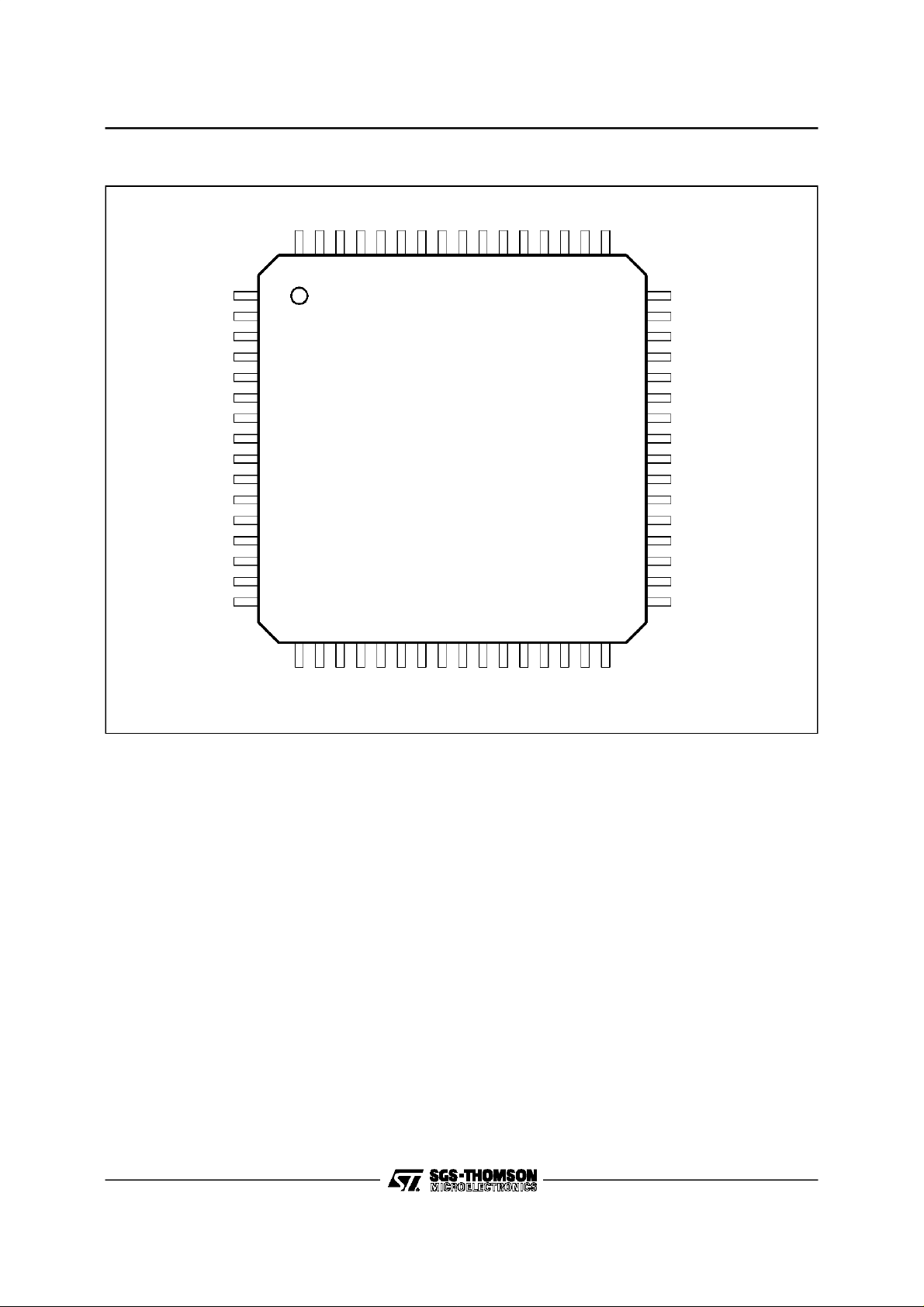
PINCONNECTIONS
TEST
V
V
TEST
TEST
V
V
V
V
V
V
TEST
TEST
TEST
TEST
TEST
TEST
Q0Q1Q2Q3Q4Q5I0
I1
I2
I3
DD
I4
VSSV
I5
64 63 62 61 60 59 58 57 56 55 54 53 52 51 50 49
1TEST
2
SS
DD
3
4
5
6
SS
DD
SS
DD
SS
DD
7
8
9
10
11
12
13
14
15
48
47
46
45
44
43
42
41
40
39
38
37
36
35
34
3316
M_C LK
MODE
CLKREC
V
DD
AGC
V
DD
V
SS
V
SS
SDA
SCL
V
DD
V
SS
NRES
D60
ERROR
D/P
17 18 19 20 21 22 23 24 25 26 27 28 29 30 31 32
D0D1D2D3D4D5D6
TEST
TEST
D7
SS
DD
V
V
CK_OUT
DD
V
STR_OUT
SS
V
0196B-01.EPS
2/23
Page 3
PIN LIST
Pin Number Pin Name Type Pin Description
SIGNAL INPUTS
51, 52, 53, 54, 55, 56 I [5..0] I In Phase Component, at twice the symbol frequency (2Fs).
57, 58, 59, 60, 61, 62 Q [5..0] I In Quadrature Component, at twice the symbol frequency (2Fs).
48 M_CLK I Master Clock Input,2Fs. Sampling Clock ofthe External A toD Converters.
FRONT END CONTROLS
46 CLKREC O 1 BitControl Signal for the External CLK VCO.Itmust be Low-passFiltered.
44 AGC O 1 Bit Control Signal for the External AGC. It must be Low-passFiltered.
35 D60 O M_CLK Divided by 60
SIGNAL OUTPUTS
26, 25, 24,23,
22, 21, 20,19
29 CK_OUT O Output Byte Clock
30 STR_OUT O Output Synchronization Byte Signal
33 D/P O Data/Parity Signal
34 ERROR O Output Error Signal. Set in Case of uncorrected Block.
2
C MICRO INTERFACE
I
39 SCL I Serial Clock
40 SDA I/O Serial Data Bus
OTHER
47 MODE I 0 =Mode A, 1 = ModeB
1, 2, 5, 6, 13, 14, 15,
16, 17, 18, 63, 64
3, 7, 9, 11, 28, 32,
37, 41, 42,49
4, 8, 10, 12, 27,
31, 38, 43, 45, 50
36 NRES I NegativeReset
D [7..0] O Output Data
TEST O Reserved for Manufacturing Test. Itmust remain unconnected
V
SS
V
DD
I Ground References
I 3.3V Supply
STV0196B
0196B-01.TBL
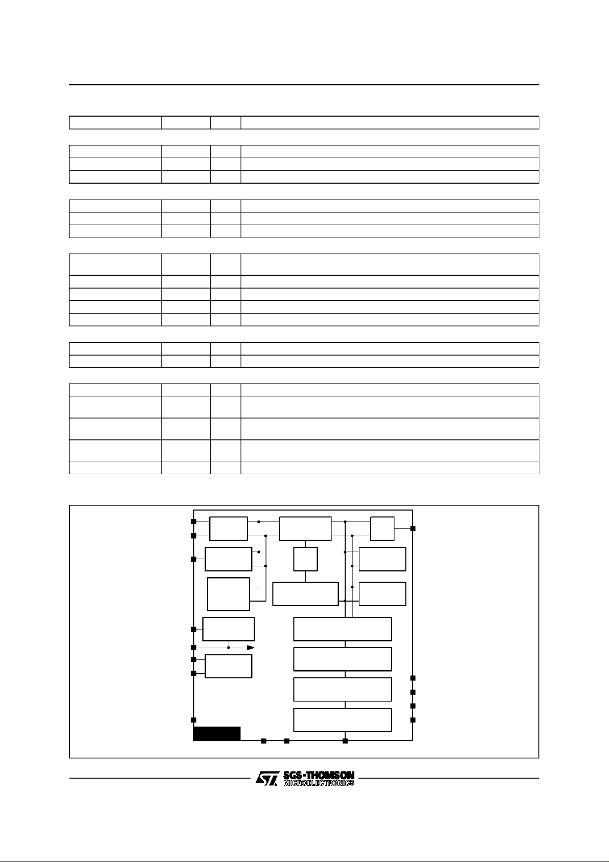
BLOCK DIAGRAM
I[5...0]
Q[5...0]
CLKREC
D60
M_CLK
SCL
SDA
MODE
NYQUIST
FILTER
TIMING
RECOVERY
CARRIER
OFFSET
MEASURE
DIVIDEBY 60
2
C BUS
I
INTERFACE
STV0196B
DEROTATOR AGC
DCO
CARRIERPHASE
TRACKINGLOOP
VITERBI DECODER
DEINTERLEAVER
REED SOLOMON DECODER
ENERGYDESCRAMBLER
V
DDVSS
D[7..0]
LOCK
INDICATOR
C/N
INDICATOR
AGC
D/P
ERROR
STR_OUT
CK_OUT
0196B-02.EPS
3/23
Page 4
STV0196B
FUNCTIONAL DESCRIPTION
2
I-I
C BUS SPECIFICATION
This is the standardI
The deviceaddress is ”1101000” ; the first byte is thereforeHex D0 for a write operation and Hex D1for a
read operation.
I.1 - Write Operation
The firstbyte is thedevice address plus the directionbit (R/W = 0).
The secondbyte containsthe internaladdress of the first registerto be accessed.
The nextbyte is written in the internal register.
The following(if any)bytes arewritten in successiveinternal registers.
The transferlasts until stop conditions are encountered.
The STV0196Backnowledgeseverybyte transfer.
I.2 - ReadOperation
The addressof the first register to readis programmed in a write operation without data, and terminated
by stop condition.
Then anotherstart is followed bythe device address andR/W= 1 ; allsuccessive bytesarenowdata read
at successivepositions starting from the initial address.
The STV0196Backnowledgeseverybyte transfer.
Example :
Write registers 0 to 3 withAA,BB,CC,DD
2
C protocol.
Start
Device Address,
Write D0
ACK
Internal
Address
ACK
Data
AA
ACK
Data
BB
ACK
Data
CC
ACK Stop
Read registers 2 and3
Start
Start
Device Address,
Device Address,
Write D0
Read D1
ACK
ACK RegisterAddress 01 ACK Stop
Data Read
BB
ACK
Data Read
CC
ACK Stop
I.3 - IdentificationRegister
This read only register gives the releasenumber of the circuit in order to ensuresoftware compatibility.
The readvalue is Hex 83 for STV0196Band Hex 81 for STV0196.
Internal Address : Hex 0B
10000011
Notes : - Unspecified register addresses mustnot be used.
- Allthe unused bits in the registers must be programmed to 0.
4/23
Page 5
FUNCTIONAL DESCRIPTION (continued)
I.4 - RegisterMap
REGISTERHEX 00
INPUTCONFIGURATION REGISTER (R/W)
Reset Value : Hex04
0 -Q(1)or Q(0) input
1 Signed(1)or positive(0) I & Q inputs
2 Nyquistfilteringon (1)/ off (0)
3 BPSK(1), QPSK(0)
4 To be set to 0.
5 To be set to 0.
6 To be set to 0.
7 To be set to 0.
REGISTERSHEX 01 TO HEX 05
VITERBI,PUNCTURERATETHRESHOLDS(R/W)
Reset Value : Hex20
rate
Hex01 VTH0 0 Th6 Th5 Th4 Th3 Th2 Th1 Th0 1/2
Hex02 VTH1 0 Th6 Th5 Th4 Th3 Th2 Th1 Th0 2/3
Hex03 VTH2 0 Th6 Th5 Th4 Th3 Th2 Th1 Th0 3/4
Hex04 VTH3 0 Th6 Th5 Th4 Th3 Th2 Th1 Th0 5/6
Hex05 VTH4 0 Th6 Th5 Th4 Th3 Th2 Th1 Th0
7/8
or
6/7
REGISTERHEX 06
VSEARCH(VITERBI)(R/W)
Reset Value : Hex19
0
H[1..0] Sync counter hysteresis value
1
2
T[1..0] Syncsearch time out
3
4
5
SN[1..0]
VITERBIerrorrateaveragingperiod.
C/Nindicator averaging period.
6 F VITERBIoperatingstatusfreeze (1)
7 A/M (0) automatic,(1)manual
REGISTERHEX 07
VERROR REGISTER(Readonly)
STV0196B
REGISTERHEX 08
VSTATUSREGISTER(Read only)
0
PR[2..0] Currentpuncture rate identification
1
2
3 LK (1) synchrofound,
(0) searchingpuncture rate
4 PRF (1) puncturerate found,
(0) searchingpuncture rate
5 unused set to (0)
6 unused set to (0)
7 CF (1)carrierfound,(0)searchingcarrier
REGISTERHEX 09
PUNCTURE RATEENABLE(R/W)
ResetValue: Hex 10 (modeA)
0 E0 (1) Puncture1/2 enabled,(0) disabled
1 E1 (1) Puncture2/3 enabled,(0) disabled
2 E2 (1) Puncture3/4 enabled,(0) disabled
3 E3 (1) Puncture5/6 enabled,(0) disabled
4 E4 (1)Puncture7/8 (modeA),6/7(modeB)
(0) disabled
5
unused
6
7
REGISTERHEX 0A
RS REGISTER (R/W)
ResetValue: HexB8
0 RS0 (1) outputclock stopped during parity,
(0) continuous
1 RS1 Output clock polarity
2 RS2 (1) allsynchro words are Hex47,
(0) synchro inversion disabled
3 RS3 Write error bit
4 RS4 Descrambleron (1), off (0)
5 RS5 Reed-Solomonon (1), off(0)
6 RS6 Normal operation (0), Reed-Solomon
correctionbytes to output(1)
7 RS7 De-interleaveron (1), off (0)
5/23
Page 6

STV0196B
FUNCTIONAL DESCRIPTION (continued)
I.4 - RegisterMap (continued)
REGISTERHEX 0B
IDENTIFICATIONREGISTER (Read only)
Reset Value : Hex83for STV0196B,
Hex 81 for STV0196
REGISTERHEX 0C
TIMINGLOOP : TIME CONSTANT(R/W)
Reset Value : Hex45
0
1
2
3
4
5
6
7 Istr externalVCO/VCXOslopepolarity(0)
beta_tmg coefficient
alpha_tmgcoefficient
positive, (1) negative
REGISTERHEX 10
CARRIEROFFSETEVALUATOR(Read only)
Signedvalueranging from 80 to 7F.
REGISTERHEX 11
AGC CONTROLREGISTER(R/W)
ResetValue: 18Hex.
0
1
2
3
4
5
6 unused
7 Iagc
AGC referencelevel m
REGISTERHEX 0D
TIMING FREQUENCYREGISTER(R/W)
Signed value ranging from80 to 7F.
REGISTERHEX 0E
CARRIERLOOP REGISTER(R/W)
Reset Value: Hex A3
0
1
2
3 unused
4
5
6
7 Deratatoron (1), off (0)
beta_carriercoefficient
alpha_carriercoefficient
REGISTERHEX 0F
DEROTATOR FREQUENCY REGISTER(R/W)
Signed value ranging from80 to 7F.
REGISTERHEX 12
AGC INTEGRATOR(R/W)
Signedvalueranging from 80 to 7F.
REGISTERHEX 13
AGC COEFFICIENT
0
G[2..0] AGC coefficient
1
2
3
4
unused
5
6
7
REGISTERHEX 14
C/N INDICATOR (Read only)
Valueranging from 00 to FF.
6/23
Page 7
FUNCTIONAL DESCRIPTION (continued)
II - ADC INTERFACE
II.1 - M_CLK Master Clock Input
This is the highest frequency clock of the chip, at
twice the symbol frequency; all other clocks are
derived from it.
This clock should be output from an externalVCO
or VCXO,controlledby CLKREC output.
M_CLK divided by 60 is available to the system
(output D60).
II.2 - I and Q Signal Inputs
Those signals are coded on 6 bits, either in 2’s
complement or as positive values : the choice is
programmablevia the Input Configurationregister.
Theπ/2 ambiguityinherentin QPSKis solvedinthe
Error Correction part.
A programmable bit in a mode register allows to
multiply by -1 the data on Q input, in order to
accommodateQPSKmodulationwithanotherconvention of rotation sense ; (this is equivalent to a
permutation of I and Q inputs, or a spectral symmetry).
III - NYQUIST ROOT FILTER
The I and Q components are filtered by a digital
Nyquist root filter with the following features:
- Input: separateIandQstreams,twosamplesper
symbol.
- Excessbandwidth : 0.35in ModeA.
- The filters may be bypassed ; in this case, the
input flow is connected to the carrier and clock
recoverysection.
Input Configuration Register
(the writtenvalueof each bit is the reset value)
Internal Address: Hex00
STV0196B
IV - TIMING RECOVERY
The timing loop comprises an external VCO
or VCXO, running at twice the symbol frequency,
controlledby the output CLKREC ; this signalis a
pulse density modulated output, at the symbol
frequency, and represents the filtered timing
error.
The loop is parametrisedby two coefficients : alpha_tmg and beta_tmg ; the 12 bit filter output is
converted into a pulse density modulation signal
whichshouldbefilteredbyananaloglowpassfilter
before commanding the VCO.
IV.1- TimingLoop Registers
Time Constant Register
InternalAddress: Hex0C
ResetValue: Hex45
Istr 1 0 0 0 1 0 1
Invert
The bit ”Istr” allows to change the polarity of the
output signal, in order to accommodateboth possibilitiesof external VCO :
TimingFrequencyRegister
InternalAddress: Hex0D
The value of this register, when the system is
locked,isanimageofthefrequencyoffset;itshould
be as close as possible to 0 in order to have a
symmetriccapturerange;reading itallowsoptimal
trimmingof thetiming VCOrange.
alpha_tmg (1 to 6) beta_tmg (0 to 9)
bit
Istr Loop Control
0 VCO frequency raises when output average
voltage raises
1 VCO frequency decreases when output
average voltageraises
Signed number
00000100
I&Q Inputs
on (1)/off (0)
Nyquist filtering
BPSK(1), QPSK(0)
Signed (1) or positive (0)
-Q(1) or Q(0) input
IV.2- Loop Equations
The external VCO is controlled by the output
CLKRECfollowedby a low pass filter.
The full analog swing of the output originates a
relative frequency shift of 2∆f , dependingon the
characteristics of the external VCO (typically a
fraction of percent).
The frequencyrange is therefore f = f
(1±∆f).
0
Neglectingthe analog low pass filter on the pulse
modulatedoutput, this loop maybe consideredas
a secondorder loop.
7/23
Page 8

STV0196B
FUNCTIONAL DESCRIPTION (continued)
The naturalfrequency and the damping factor maybe calculatedby the following formulas :
F
ω
n
s
=
=
f
n
2π
where β is programmed by the timingregister :
K
isthe constantof the VCO :
0
is the phase detector ; its value dependson
K
d
the roll-offvalue andon the power of the signal.
is the symbol frequency,∆f is the half range of the VCO
F
s
d
with α=2
β
beta_tmg
beta_tmg
(ModeA)
(Mode B)
(ModeA) or ξ=
Therefore f
or f
= 19.210−6⋅ m⋅ Fs⋅ √∆f2
n
= 14.610−6⋅ m ⋅ Fs⋅ √∆f2
n
The dampingfactor is : ξ=
0.247 ⋅ m ⋅√∆f ⋅ 2
or ξ=
√2
beta_tmg
alpha_tmg
α
2
K0K
√
beta_tmg can only take value from 0 to 9 ; if beta_tmg= 0, theloop becomesa first orderone.
alpha_tmg can take any valuefrom 1 to 6 ; ifboth alpha_tmgand beta_tmgare null, theloop is open; the
duty cycle of the CLKRECoutputis controlled by writtingthe timing frequencyregister.
The next curve shows the natural frequency for a symbol frequencyof 20Mbd, in Mode A, with nominal
referencelevel m = 24 as a functionof theVCO relativefrequencyhalf range∆f, for differentvaluesof the
register value beta_tmg.
Thefollowingchartgivesthevalueofthedampingfactoras afunctionof theVCOrelative range,for different
combinationsof alpha_tmgand beta_tmg,noticingthat the damping factor only depends on the valueof
α
or (2 .alpha_tmg - beta_tmg).
√β
√β K
2π
0Kd
β=
K
0
:Kd= 0.977m2(inMode A),
or K
where m is the programmedreferencelevel
(see AGC part),reset value: m= 24
alpha_tmg + 12
0.188 ⋅ m ⋅√∆f ⋅ 2
beta_tmg
√2
beta_tmg
2
=
2
d
.
∆f
.
26
= 0.564m2(in Mode B).
alpha_tmg
(ModeB).
8/23
Page 9

FUNCTIONAL DESCRIPTION (continued)
Figure 1 : NaturalFrequency for Fs = 20MBauds
100
reset value
10
1
NATURALFREQUENCY (kHz)
STV0196B
be ta _tmg
9
8
7
6
5
4
3
2
1
0.1
0.0001 0.001
Figure2 : Damping Factor
10
reset value
1
KSI
0.1
0.0001 0.001
VCO Relative Frequency Range (∆f)
0.01
0196B-03.EPS
8
7
6
5
4
3
2
1
0
2alpha_tmg
- beta_tmg
0.01
VCO Relative Frequency Range (∆f)
Example :
the VCO is trimmed from 39.9MHz to 40.1MHz when the VCO control output CLKREC goes from duty
cycle 0 to 100%. The peak-to-peakrelative range is therefore0.5% and ∆f = 0.0025 ; the reset values of
the parameters (alpha_tmg = 4, beta_tmg= 5) leads to a natural frequencyof 2.6kHz, with a damping
factor of 0.84.
9/23
0196B-04.EPS
Page 10

STV0196B
FUNCTIONAL DESCRIPTION (continued)
V - CARRIER RECOVERY ; DEROTATOR
The input of the circuit is a pair of demodulated
signals ; however, theremay subsist some phase
error not correctedby the front end loop.
Furthermore, the demodulation may be done at
constant frequency; the tuner is trimmed in order
to make the useful signal bandwidth centered on
this demodulationfrequency; inthatcase,acarrier
offsetfrequencymay subsist;itisfixedbythemean
of theon-chip derotator which acts as a fine tuning
carrierloop.
The derotator frequency range is limited to an
intervalcorresponding to ±F
V.1- Loop Parameters
Like the timing loop, the carrier loop is a second
order systemwhere two parameters α and β may
be programmed respectively with alpha_carand
beta_car.
Carrier Loop Parameter Registers
Internal Address: Hex0E
10100011
alpha_carrier beta_carrier
ON/OFF
Derotator
Derotator FrequencyRegister
Internal Address: Hex0F
Signed number
/16.
s
The shaded area correspondto the reset values.
beta_car
(reg. value)
=2π/ω
T
n
(symb per)
(kHz) for
f
n
F = 20Mbd
alpha_car
(reg. value)
01 2 34567
n
NA 907 642 454 321 227 160 113
22 31 44 62 88 125 177
Damping Factor
0NANA NA NANANANANA
1 NA 0.89 0.63 0.44 0.31 0.22 0.16 0.11
2 NA 1.77 1.25 0.89 0.63 0.44 0.31 0.22
3 NA 3.54 2.51 1.77 1.25 0.89 0.63 0.44
4 NA 7.09 5.01 3.54 2.51 1.77 1.25 0.89
5 NA 14.18 10.03 7.09 5.01 3.54 2.51 1.77
VI - CARRIER OFFSETEVALUATOR
An 8 bit register may be readat any time; it gives
a signed value proportionnal to the carrier frequencyoffset according to theexpression:
∆f =1.8 . 10
where F
-6.m2
is the symbol frequency, m the symbol
s
.N.Fs(in mode A)
module (AGC reference), N the read value.
The maximum value for N is reached in nominal
conditions for a carrier offset of 16% of F
s
;if
greater,Nremains saturated,givinga reliablesign
indication over more than±50% F
range.
s
CarrierOffsetRegister
InternalAddress: Hex10
Signed number
This 8 bit R/W register may be written at any time
to force the central frequency of the derotator to
start the carrier research,orread,when theloopis
locked,in order to know the current carrier offset
(one LSBcorrespond to F
/2048).
s
V.2- Loop Equations
The naturalpulsation is :
ω
= 10−3⋅ fs⋅ √m ⋅ 2
n
beta_car
and thedampingfactor is :
ξ=0.128 ⋅ 2
alpha_car
m
⋅ √
beta_car
2
.
wheremis thereferencevalue(seeAGCregisters ).
The next table gives for the nominal amplitude
m = 24 the natural period (in symbols), and the
dampingfactorforthepossiblevaluesof alpha_car.
Asan example,thecorrespondingnaturalfrequency
isgivenassumingasymbolfrequencyof20MBauds.
10/23
VI.1 - Lock Indicator
This 1 bit Carrier Found flag may be read (see
ViterbiStatus register)at anytime ; it indicates that
a QPSK signalis found, and thatthe carrierloop is
closed; Thisflag allowstodetectfalselockthatcan
happenif theloop bandwidthissmallregardingthe
frequency offset.
VII - CARRIER TONOISE INDICATOR
InternalAddress : Hex14. Readonlyregister.
b7 b6 b5 b4 b3 b2 b1 b0
This registercanbe used to estimatethe carrierto
noise level (Eb/No)in a rangefrom 4 to 16dB.
The registervalue dependson boththe AGCreference level”m” (see paragraph VIII)and thecontrol
bits”SN[1..0]”(seeparagraphIX). Formore details
about how to usethis register,please refer to the
Annexe1.
Page 11

FUNCTIONAL DESCRIPTION (continued)
VIII - AGC CONTROL
Themodulusoftheinputiscomparedtoaprogrammable threshold; the difference is scaled by the
AGC coefficient, then integrated; the result is converted into a pulse density modulation signal to
drive theAGCoutput;itmaybe filteredbyasimple
analogue filterto controlthe gain command of any
amplifier before the Ato D converter.
The 8 integrator MSB’smay be read or written at
any timebythe micro; when written, the LSB’s are
reset. Theintegrator value is the level of the AGC
output, after low pass filtering ; it gives an imageof
the inputsignal power,whateverthis signal is,and
can beused to point the antenna.
The coefficientmay be reset by programmation;in
that case, the AGC reduces to a programmable
voltage synthesiser.
The AGC reference level ”m” value impacts the
value of the following functions :
- carrierto noise indicator (see paragraph VII)
- the carrierloop (seeparagraphV.2)
- the timing loop (paragraphIV.2)
- carrieroffset evaluator(paragraphVI)
Control Registers
Internal Addresses: Hex11
Iagc 0 0 1 1 0 0 0
Invert
signal
Reserved AGC reference
level (”m”)
Internal Addresses: Hex12
AGC integrator value (signed)
(Read/write register)
Internal Addresses: Hex13
00000010
Reserved G[2..0] :
AGC coefficient
The 8bitsignedvalue inthe integratoristheimage
of the AGC output; reading this value gives an
image of the RF signalpower.
Aconstanterroron the modulusleads to a ramp at
the outputof theintegratorwithvalue :
AGC_Int = 2
AGC_Coeff-16
.error
As a consequence,for the reset conditions,a constant signal of nullvalue (error =24) should cause
the outputAGCduty cycle to go from100%to 0%
22
symbolperiods, or 8.7ms at 20MBauds.
in 2
If Iagcis set, the sign of the integratoris inverted.
STV0196B
IX- VITERBI DECODER AND SYNCHRONIZA TION
The convolutives codes are generated by the
polynoms Gx = 171
and Gy = 133
oct
The Viterbidecodercomputesfor each symbolthe
metrics of the four possible paths, proportional to
the square of the Euclidian distance between the
receivedI and Q and the theoreticalsymbolvalue.
The puncturerate and phase are estimatedon the
errorrate basis.
Five rates are allowed and may be enabled/disabled through register programming :
1/2, 2/3, 3/4,5/6,7/8.
In ModeB, 7/8 is replaced by 6/7.
For each enabled rate, the current error rate is
compared to a programmable threshold; if it is
greater,anotherphase(oranotherrate)istrieduntil
the goodrate is obtained.
A programmable hysteresis is added to avoid to
loose the phaseduringshort term perturbation.
The rate may also be imposed by the external
software, and the phase is incremented only on
micro request ; the error rate may be read at any
time in order to use other algorithm than implemented.
The decoder is accessedvia a set of 9 registers :
ThresholdRegisters (VTH0 to VTH4)
InternalAddress : Hex1 (VTH0)to 5 (VTH4)
ResetValue: Hex20
VTH0 0 Th6 Th5 Th4 Th3 Th2 Th1 Th0 rate 1/2
VTH1 0 Th6 Th5 Th4 Th3 Th2 Th1 Th0 rate 2/3
VTH2 0 Th6 Th5 Th4 Th3 Th2 Th1 Th0 rate 3/4
VTH3 0 Th6 Th5 Th4 Th3 Th2 Th1 Th0 rate 5/6
VTH4 0 Th6 Th5 Th4 Th3 Th2 Th1 Th0
Foreachregister,bits6 to 0 representan error rate
threshold : the average number of errors happening during 256 bit periods;the maximumprogrammable value is 127/256 (higher error rates are of
no practicaluse).
PunctureRate Enable register
InternalAddress: Hex09
ResetValue: Hex10 (Mode A)
0 0 0 E4E3E2E1E0
E4 : enablePunctur edRate7/8(M odeA)or6/7(ModeB)
E3: enablePuncturedRate 5/6
E2: enablePuncturedRate 3/4
E1: enablePuncturedRate 2/3
E0: enableBasic Rate 1/2
oct
.
Threshold
Value
rate7/8
or6/7
11/23
Page 12

STV0196B
FUNCTIONAL DESCRIPTION (continued)
IX - VITERBI DECODER AND SYNCHRONIZATION (continued)
Other Registers
VSEARCH
Internal Address: Hex06
A/M F SN [1..0] TO [1..0] H [1..0]
A/M : Automatic/manual
F : Freeze
SN [1..0] : Averagingperiod.It gives thenumberof
bitsrequiredto calculat ethe rate error:
SN [1..0] Number of bits
00 1.024
01 4.096
10 16.384
11 65.536
Reset Value : SN=01 (4096 bits)
The SN[1..0] bits also in pacts the C/N
indicator(seeparagraphVII).
TO [1..0] : Time out value. It programs the
maximumdurationofthesynchroword
researchin automaticmode;ifnosync
is foundwithinthis duration,thephase
is incremented.
TO [1..0]
00 16
01 32
10 64
11 128
Reset Value : TO=10 (64K bit periods).
Time out
(in 1024 bit periods)
H [1..0] : Hysteresis value. It programs the
maximum value of the Sync counter.
The unit is the block duration
(204bytes in ModeA).
H [1..0]
00 forbidden value
01 32
10 64
11 128
Reset Value : H=01 (32 blocks).
Sync Counter max value
(in blocks periods)
In Mode A, the sync word is 47hex and it is complemented to B8hexfor every 8thblock.
An Up/DownSynccountercountswheneverasync
word is recognized with the good timing, and
counts down for each missing sync word ; this
counter is boundedby a programmablemaximum
value; when this value is reached, the LK bit
(”locked”) is set in VSTATUS register; when the
eventcountercountsdownuntil 0, thisflagis reset.
VSEARCH bit 7 (A/M) and bit 6 (F) programs the
automatic/manual(orcomputeraid ed)searc hmode :
- if A/M =0 and F=0 :automatic mode; successive
enabledpuncturedratesare triedwithallpossible
phases, until the systemis lockedand the block
12/23
synchrofound ; this is the default (reset) mode.
- if A/M=0 and F=1, the current puncture rate is
frozen, if no sync is found, the phase is incremented, but not the rate number; this mode allows to shortenthe recoverytimeincaseof noisy
conditions:the puncturerate is not supposed to
change in a given channel.
In a typicalcomputeraided implementat i on,the researchbeginsin automaticmode;the micro reads
the errorrateor thePRF flagin orderto detectthe
captureofasig nal ;thenitswitc hesFto 1,untilanew
channelis requestedby theremot econtrol.
- if AM=1 : manual mode; in this case, only one
puncture rate should be validated, the systemis
forcedto thisrate,onthe currentphase,ignor ingthe
time-outregisterandtheerrorr ate;inthismode,each
0 to 1 transitionof thebit Fleadsto aphase incrementation,al l ow ingfullcontro loftheoperationbyan
externalmicro bychoosingthe lowesterrorrate:
Rese tV alue:A/ M=0 ,a ndF= 0;auto maticsearc hmode
VERROR (Read only register)
InternalAddress: Hex07
At any time, the last valueof the error ratemaybe
readinthisregister(unlikeVTH,thepossiblerange
is 0 to 255/256).
VSTATUS (Read only register)
InternalAddress: Hex08
CF 0 0 PRF LK PR [2..0]
CF : CarrierFoundflag(seecarrierrecovery)
PRF : PunctureRate Found
LK : Locked/searchingthesyncword
PR [2..0] : CurrentPuncture Rate
Punctured 7/8(Mode A)
ERROR RATE
CF when set, indicates that a QPSK
signal is present at the input of the
Viterbi decoder.
PRF indicates the state of the
puncture rate re search : 0 for
searching, 1 when found ; this bit is
irrelevantin manualmode.
LKindicates the stateof the syncword
research: 0 forsearc hing,1whenfound.
It hold the currentpuncturerate indice
with the correspondance:
Punctured Rate Regiter Value PR[2..0]
Basic 1/2 100
Punctured 2/3 000
Punctured 3/4 001
Punctured 5/6 010
011
or 6/7 (Mode B)
Page 13

FUNCTIONAL DESCRIPTION (continued)
X - CONVOLUTIONAL DE-INTERLEAVER
This is a 204 x 12 convolutional interleaver in
Mode A; the periodicity of 204 bytes for syncbyte
is preserved.
Thede-interleavermaybeskipped(seeRSregister).
XI -REED-SOLOMONDECODER
ANDDESCRAMBLER
The input blocks are 204 byte long with 16 parity
bytes in Mode A; the synchro byte is the firstbyte
of theblock.Up to 8 byte errors may be fixed.
Code Generatorpolynom:
g(x) = (x - ω
0
)(x-ω1) (...)(x - ω15)
over theGalois Field generated by :
8+X4+X3+X2
X
+1=0
Energy dispersal descrambler :
Outputenergy dispersal descrambler generator :
15+X14
X
+1
The polynom is initialised every eight blocks with
the sequence 100101010000000. The synchro
words are unscrambled.
Control register: RS register
Internal Address: Hex0A
The resetvalueis written in each register cell
RS7 RS6 RS5 RS4 RS3 RS2 RS1 RS0
10111000
RS7 : De-interleaverEnable
If 1, the input flow is deinterleaved.
If 0, the flow is not affected.
RS6 : If 0, Output data are corrected bytes
(normal operatingmode).
If1,OutputdataareReed-Solomoncorrec tion
bytes(errorcountmode)(seeNote 1).
STV0196B
RS5 : Reed-Solomon Enable
If 1, the input code is corrected.
If 0,nocorrectionhappens;all the data are
fed to the descrambler.
The errorsignal remainsinactive.
RS4 : DescramblerEnable
If 1, the output flow from Reed-Solomon
decoderis descrambled.
If 0, the descrambler is desactived.
RS3 : Write Error Bit
If RS3=1, anduncorrectibleerrorhappens,
the MSBof the first byte followingthe sync
byte is forcedto 1afterdescrambling.
RS2 : Super SynchroSuppression
If RS2=1, all synchro bytes are Hex47 in
mode A.
If RS2=0, the synchro is complemented
every8thpacket. Itallows, whenscrambler
is off, to provide RS coded signals for use
in low-cost SMATV interface.
RS1 : Output Clock Polarity
If RS1=0,data and controlsignals change
during high to low transition of CK_OUT.
If RS1=1, they change during the low to
high transition.
RS0 : Output Clock Configuration
If RS0=0,CK_OUT is continuous.
If RS0=1,CK_OUTremains low duringthe
parity bits.
Note 1 : When RS6 = 1, the outputdata are the correction bytes
Remark : Output datas are meaningless when error flag (Pin 34)is
applied to data incoming the Reed-Solomonblock.
The number of bits at 1 in these output data represent
therefore the number of errors remaining at the outputof
VITERBI decoder.
All null output data mean no error left after VITERBI
decoding.
set to high level.
Figure3
CK_OUT
D/P
STR_OUT
ERROR
RS0=0, RS1=0
RS0=1, RS1=0
RS0=0, RS1=1
RS0=1, RS1 =1
No Error Uncorrected Pa cke t
Data Parity
Data Parity Data Parity
No Error
0196B-05.EPS
13/23
Page 14

STV0196B
ABSOLUTE MAXIMUM RATINGS
Maximumlimits indicate where permanent device damagesoccur,continuousoperation at these limits is
not intended and should be limited to those conditions specified insection ”DC ElectricalSpecifications”.
Symbol Parameter Value Unit
V
V
T
T
P
Notes : 1. AllVDDto be tied together
Power Supply(1) -0.3 to4 V
DD
V
Voltage on Input pins (2) -0.3 to VDD+ 0.3 V
I
Voltage on Output pins -0.3to VDD+0.3 V
o
Storage Temperature -40 to +150
stg
Operating Ambient Temperature -10 to +85
oper
Power Dissipation 1.5 W
D
2. SCL, SDA, NRES Pins can be tied to 5V ± 10% with an impedance ≥ 2kΩ (remark in these conditions the input leakage current
becomes higher than 10µA).
o
C
o
C
0196B-02.TBL
DC ELECTRICALCHARACTERISTICS (VDD=3.3V,T
=25oC unless otherwise specified)
amb
Symbol Parameter Test conditions Min. Typ. Max. Unit
3.0
3.3
V
I
V
V
V
V
I
C
V
V
Operating Voltage 0oC ≤ T
DD
Average Power Supply Current C
DD
Input LogicLow Voltage except M_CLK
IL
Input LogicHigh Voltage except M_CLK
IH
Input LogicLow Voltage for M_CLK
IL
Input LogicHigh Voltage for M_CLK
IH
Input LeakageCurrent VIN= 0V and V
LK
Input Capacitance 3.5 pF
IN
Output LogicLow Voltage
OL
Output LogicHigh Voltage
OH
o
C<T
0
LOAD
M_CLK = 60MHz
M_CLK = 60MHz -0.3
M_CLK = 60MHz -0.3
C
LOAD
M_CLK = 60MHz 2.4
≤ 70oC
oper
<85oC, M_CLK ≤ 55MHz
oper
= 20pFon all outputs,
DD
= 20pF,I
LOAD
= 2mA,
3.15
2.0
2.2
3.6
3.3
3.45VV
300 480 mA
0.8
3.6VV
0.8
3.6VV
10 µA
0.5 V
V
Note :Thisproduct doesn’twithstand the MIL883C Norm at 2kV,but onlyat 1.5kV(all VDDtiedtogether).
TIMING CHARACTERISTICS
Symbol Parameter Min. Typ. Max. Unit
PRIMARY CLOCK (see Figure4)
t
M_CLK
t
HIGH
t
LOW
t
R
t
F
Master Clock Period 0oC ≤ T
o
0
C<T
Clock High Time 6 ns
Clock Low Time 6 ns
Clock Rising Edge 4ns
Clock FallingEdge 4ns
oper
oper
≤ 70oC
<85oC
I[5:0],Q[5:0] INPUT SPECIFICATIONS(see Figure 5)
I,Q stablebefore M_CLK 4 ns
t
SU
t
I,Q stable after M_CLK 4 ns
H
D60 OUTPUT CHARACTERISTICS (see Figure 6)
D60 period (Tm_clk * 60)
t
60
D[7:0],D/P,CK_OUT,STR_OUT,ERROR OUTPUT CHARACTERISTICS
Bit RS1= 1 inregister RS ( adr= 0x0A) (see Figure 7)
t
CKSU
t
D[7:0],D/P,STR_OUT,ERRORstablebeforeCK_OUT FallingEdge 32 ns
D[7:0],D/P,STR_OUT,ERROR stable afterCK_OUT Falling Edge 32 ns
CKH
Bit RS1= 0 inregister RS ( adr= 0x0A) (see Figure 8)
t
CKSU
t
D[7:0],D/P,STR_OUT,ERRORstable before CK_OUT RisingEdge 32 ns
D[7:0],D/P,STR_OUT,ERROR stable afterCK_OUT Rising Edge 32 ns
CKH
16.6
18.2
-10
(Tm_clk*60)
+10
ns
ns
ns
0196B-03.TBL
0196B-04.TBL
14/23
Page 15

STV0196B
I2C BUSCHARACTERISTICS (see Figure9)
Symbol Parameter Test Conditions Min. Typ. Max. Unit
V
V
V
V
I
C
I
t
f
SCL
t
BUF
t
HD,STA
t
LOW
t
HIGH
t
SU,STA
t
SU,STO
t
HD,DAT
t
SU,DAT
t
R,tF
C
Notes : 1. An impedance higher than 2kΩ is required when SDA and SCL are tiedto a 5V± 10% voltage line.
Input LogicLow Voltage
IL
Input LogicHigh Voltage See Note 1
IH
Output LogicLow Voltage
OL
Output LogicHigh Voltage
OH
Input LeakageCurrent VIN=0VtoVDD, see Note 2 -10 10 µA
LK
Input Capacitance 3.5 pF
IN
Output SinkCurrent VOL= 0.5V 10 mA
OL
Pulse Width of Spikes which mus t be
SP
suppressed by the Input filter
C
= 20pF, I
LOAD
M_CLK = 60MHz, see Note 1 2.4
LOAD
= 2mA,
SCL Clock Frequency 0 400 kHz
Bus Free Time between a STOP and START
Condition
Hold Time (repeated) START Condition. After
this period,the first clock pulse isgenerated.
Low Periodof the SCL Clock
High Period of the SCL Clock
Set-up Time for a repeated START Condition 0.6 µs
Set-up Time for STOP Condition 0.6 µs
Data Hold Time See Note 3 0 0.9 µs
Data Set-upTime See Note 4 100 ns
Rise and Fall Time of both SDA and SCL
See Note 5 20 +
signals
Capacitive Load for each Bus Line 400 pF
B
2. Leakage currentexceeds ± 10µA whenSDA and SCL are tied to a 5V ± 10% line.
3. A devicemust internally providea holdtime ofat least300ns for theSDA signal (refered tothe V
to bridge the undefined region of the falling edge of SCL.
The maximum tHD,DAT has onlyto be met if the device does not stretch the low period (t
4. A fast-mode I
met. This will automatically be the case if the device does not stretch the low period ofthe SCL signal. If such a device does
stretch the low period of the SCL signal, it must output the next data bit to the SDA line t
(according to the standard-mode I
= total capacitance of one bus line in pF.
5. C
B
2
C bus device can be used ina standard-mode I2C bus system, but the requirement t
2
C bus specification) before the SCL line is released.
-0.3
2.0
0.8
5.5VV
0.5
5.5VV
050ns
1.3 µs
0.6 µs
1.3
0.6
300 ns
0.1 C
B
of the SCL signal) in order
IH Min.
) of the SCL signal.
LOW
R Max.+tSU,DAT
≥ 250ns must then be
SU,DAT
= 1000 +250 =1250ns
µs
µs
0196B-03.BTBL
15/23
Page 16

STV0196B
Figure4
Figure5
Figure6
Figure7
D60
M_CLK
0.8V
M_CLK
I,Q
t
HIGH
2.0V
t
M_CLK
(VIL+VIH)/2
t
SU
t
60
t
R
t
LOW
Figure8
t
F
0196B-06.EPS
t
H
0196B-07.EPS
0196B-08.EPS
CK_OUT
D[7:0], D/P.
STR_OUT,
ERROR
Figure9
SDA
SCL
t
BUF
t
HD,S TA
t
LOW
t
HD,DAT
t
CKSU
CK_OUT
D[7:0], D/P.
STR_OUT,
t
CKH
t
HIGH
t
F
t
R
ERROR
0196B-09.EPS
t
SU,DAT
t
SU,STA
t
HD,STA
t
CKSU
t
CKH
t
SP
t
SU,STO
0196B-10.EPS
0196B-11.EPS
16/23
Page 17

APPLICATION DIAGRAM : STV0196B/STV0190Fixed20 MBauds Application
C BUS
2
I
SDA
SCL
RESET
D/60
1
ERROR
D/P
GND
12345
STR_OUT
CK_OUT
DATA
OUTPUTS
D7
D6D5D4D3D2D1D0
678
9
101112
13
STV0196B
DDL
V
+5V
3.3kΩ3.3kΩ
DDL
V
C37
1nF
C35
1nF
R37
R34
82kΩ
R32
C34
100nF
20 to 28V
82kΩ
39kΩ
1234567
R36
8.2kΩ
C36
R27
8 9 10 11 12 13 14
Ω
10k
220kΩ
L1 1µH
40MHz
Q1
C26
BF959
C33
D1
82pF
1nF
R30
22kΩ
1nF
BB909
R22
22kΩ
C25
39pFR21
330Ω
C24
220pF
LM324
X1
+5V
R23
DDL
V
DDL
V
DDL
V
R31
8.2kΩ
5V
R18 47Ω
C23
100nF
74F04
31
32
30
33343539
36373840
4142434445464748
51
50
49
DDL
V
R19
560Ω
R20
10kΩ
28
123456789
C13
100nF
DDL
V
C12
22µF
DDL
V
17
18
19
26
27
28
29
23
24
25
STV0196B
55
54
53
52
26
27
R3 68Ω
24
25
C14
100nF
DDA
C10
V
Q
100nF
23
STV
C15
100nF
58
576256
21
22
019
C16
100nF
C11
100nF
I
20
21
22
16
15
14
DDL
V
DDL
V
DDL
V
DDL
V
12345678910111213
61
60
59
19
20
63
64
DDL
V
C22
22µF
C21
100nF
16
17
18
Pins 4-3-10-12Pins 27-31Pins 38-43-50
C52 C50 C51
DDL
V
C49 C44
DDL
V
C43
DDL
V
C48
DDL
V
C45 C42 C47 C46
0
10
111213
C17
100nF
C18
100nF
DDA
V
R4 68Ω
R2
1kΩ
14 15
C20
100nF
C19
22µF
DDL
V
TUNER
BSFR68G15
R1
1kΩ
+5VA
C6
100nF
C7
220µF
C5
+12V +5VA
C4
+5VA
100nF
C2
C3
C1
100nF
100nF
100nF
100nF
C8
100nF
12V5V5VA
20V to 28VLNB
22µF
35V
22µF
12V
Supply
& Control
DDLVDDA
V
22µH
22µH
5V
3.3V
0196B-12.EPS
17/23
Page 18

STV0196B
APPLICATION DIAGRAM : STV0196B/STV0190MultirateApplication
D7D6D5D4D3D2D1
DDL
V
26
27
28
25
22
23
24
32
STROUT
DDL
V
31
CKOUT
D/60
29
30
VCO ADJ
(PWM)
SDA
SCL
RESET
ERROR
D/P
3.3kΩ3.3kΩ
+5V
TC74SU04
33343539
C40
100nF
1nF
R37
R36
C36
1nF
R31
2 x BB909A
R18 47Ω
100nF
36373840
DDL
V
4142434445464748
DDL
V
82kΩ
DDL
V
8.2kΩ
51
50
DDL
V
49
DDL
V
54
53
52
STV0196B
55
59
58
576256
8.2kΩ
20
21
22
7
8
9
C16
100nF
C17
100nF
C11
R4 68Ω
100nF
I
74F04
R20
26
27
28
R19
560Ω
1
234
Ω
C13
100nF
R3 68
F
DDL
µ
V
C12
22
DDA
V
10kΩ
24
25
5
C14
100nF
C10
Q
23
STV0190
6
C15
100nF
100nF
C39
R40 22kΩ
22µF
C30
2.2nF
R33
1kΩ
C35
1nF
R34
82kΩ
R32
39kΩ
+12V
R41 68Ω
1234567
C41
22µF
R43
1kΩ
D3
5.1V
C37
R35 1kΩ
C34
100nF
20 to28V
LM324
8 9 10 11 12 13 14
R29
R28
22kΩ
100kΩ
1nF
C32
R26
10kΩ
C31
33nF
R25
10kΩ
C30
220pF
C29
15pFL20.33µH
C28
C27
22µF
100nF
C26
R23
82pF
10kΩ
R23
10Ω
+5V
Q1
BF959
R30
1kΩ
C33
10nF
R27 220kΩ
D2D1
R22
22kΩ
C25
39pF
R21
330Ω
5V
C23
C24
220pF
C18
R2
21
60
19
10
100nF
1kΩ
D0
19
20
61
17
18
111213
C19
22µF
DDA
V
V
17
18
16
15
14
DDL
V
DDL
V
DDL
V
DDL
V
Pins 4-3-10-12Pins 27-31Pins 38-43-50
C52 C50 C51
DDL
V
C48 C44
DDL
V
C43
DDL
V
C49
DDL
V
12345678910111213
63
64
DDL
V
C22
22µF
C21
100nF
C45 C42 C47 C46
16
14 15
C20
100nF
DDL
18/23
TUNER
BSFR68G15
R1
1kΩ
+5VA
C6
100nF
C7
220µF
+12V +5VA
+5VA
C5
C4
100nF
100nF
C8
100nF
20V to 28VLNB
12V5V5VA
DDLVDDA
V
22µF
22µH
100nF
C2
C3
100nF
C1
100nF
35V
22µF
12V
Supply
& Control
22µH
5V
3.3V
0196B-13.EPS
Page 19

ANNEXE1 : C/N ESTIMATION
The C/N indicator register permanently reports a
value SwhichdependsontheC/Nlevelat theinput
of theSTV0196B.
TheC/Nindicatoroffersaprogrammablesensitivity
which allows a reliableC/N estimationovera wide
Eb/No range (4dB to 16dB typically) ; this is particularlyuseful to optimizethe dish positioning.
Remark :
C
=
N
In this note,we have assumed that :
E
b
⋅ 2 (PR), PR :Puncture Rate
N
o
The sensitivityof theC/Nindicatorisdependanton
the SNbits of theregisterVSEARCH(Hex06) and
on theAGC function reference level ”m”.
A - SUGGESTEDPROCEDURE TO RELIABLY
ESTIMATE THE ACTUAL C/N
As no simple mathematical low ensumes a good
matchingbetweenthe C/N indicatorandtheactual
C/N, the method relies on a comparaison of the
value S (reported by the C/N indicator) with a
reference look-up table which has been realized
under well controlledconditions.
Basically there are 3 steps in the C/N estimation
software.
1. To collect C/N indication (under adapted
condi t ions).
2. Indication scaling and correction versus the
puncturerate
3. Comparaisonwith the look-up table
A.1 - Tocollect C/N Indication
The purpose of this first step is to collect the C/N
indicator with the appropriate sensitivity (SN bits
and AGCreference level m).
Basically :
- ThevaluereportedbytheC/Nindicatorispropor-
tional to the Number of bits (at the output of the
VITERBI decoder)selected by the SN bits.
- The AGCreferencelevel is only changed to ap-
preciate the high Eb/No ratios. This second parameterhas to be usedwith some care.
Procedure :
Before to make an estimation, the
VSTATUSregister (internaladdress Hex 08) must
be checkedto makesure that :
- a carrier is actuallypresent (bit 7)
- puncturerate is found (bit 4)
- puncturerate is known (bits0-1-2)
STV0196B
Remark
estimationwithout informationsaboutthepuncture
rate (useful when the dish is still very far from
optimum position), in such case the puncture rate
is forced.
The C/N indicatorregister has no overflow detection,so itis necessaryto startthemeasure withthe
lowest sensitivity (SN = 00) and to gradually increaseit(usingSNbits).Duetothenoise,theresult
S of the measure may have a lot of dispersion,
consequently it is recommended to measure S
severaltimes(typically100 times) and tocalculate
the averagevalue.
Remark :
readingsof theregister mustbe higherthan :
with BC : Bit Count(selectedby SNbits)
Whenthe currentaverage value of the measureS
is lowerthan 63, themeasure is done again with a
higher sensitivity. With this care the new C/N
measur e S does no t ove rflo w the c ount er
(the countingtime is multipliedby 4 at each step).
In practicesome margin isgivento this threshold:
a higher sensitivity is selected when the average
value of S is lowerthan 60.
When the maximum SN value is reached
(SN = 11⇔ to 65 536 bits at the output of the
VITERBI decoder), the sensitivity can be further
increased by lowering the AGC reference level
(para meter m, internal address Hex11,
bit 0 to bit 5).
Remark :
referencelevel only in case of high C/N conditions,
thentochangethereferencelevelhasnoimportant
influenceonthebiterrorrate(BER).Inother words,
a completeteC/N estimationcan be run during the
operationof thereceiver.
When the highest possible sensitivity is found
the result S (average value) is ready for further
process.
: Optionally, it is possible to make an
The requred duration tWbetween two
t
W (Min.)
BC
=
BR
BR = 2 (Fs)x (PR)
Fs : Symbol Rate
PR : Puncture Rate
There is the need to change the AGC
19/23
Page 20

STV0196B
ANNEXE1 : C/n ESTIMATION (continued)
A.2-Scalinga ndCorr ectio nversusPun ctu re Rate
Scaling
This simple operation is recommended to easily
compare data which have been recorded under
differentsensitivity conditions.To do so, theresult
S oftheC/Nindicationis multipliedby a coefficient
so that the scaled value would correspond to a
measure done with the highest counting period
(SN =11).
Remark :
beenrecor dedafterchangingtheAGCreferencelevel.
Scaling operation :
factor= 64when C/N estimation is donewithSN = 00
factor= 16when C/N estimation is donewithSN = 01
factor= 4whe nC /Nestimationisdone withSN =10
factor = 1 when C/Nestimation is done with SN = 11
Correctionversus puncture rate
This correction is not required when a reference
look-up table have been memorized for eachpossible puncturerate. When required,the correction
is done with respect to the puncture rate PRref of
the referencelook-up table:
Scalingis not donefor res ul tswhic hhave
Scaled_value= (S) x (factor)
Scorrected=(S)⋅
PRcurrent
PRref
PR current : the puncture currentlyidentified with
the bits0,1,2of VSTATUSregister.
A.3 - Comparingwith the look-up table
In the application the read value Srs (scaled and
corrected)will seldomexactly match a value of the
look-up table ; consequentlythere will be the need
for some interpolation.
Tomakeitsimple,alinearinterpolationispreferred,
with such a solution a good precision can be
achievedwhenthe look-uptableisbuiltwitha small
step for theC/N (or Eb/No).
Interpolation
Generally Ssr will be between two values of the
reference look-up table : V
with V
corresponding to C/N
(C/N
(Max.)
corresponding C/N
(Min.)
) - (C/N
(Min.)
(Min.)
) =0.5dB).
≤ Ssr ≤ V
(Min.)
and V
(Max.)
(w ith typ i ca lly
(Max.)
(Max.)
The calculated C/N correspondingto Ssris :
V
− Ssr
C/N = C/N
(Max.)
−C/N
(Max.)
− C/N
(Min.)
⋅
V
(Min.)
(Min.)
− V
(Max.)
in above calculation C/N (or Eb/No) are given in
algebraic value (not indB).
,
20/23
Page 21

ANNEXE1 : C/n ESTIMATION (continued)
B - FLOW CHART
Following is a simplifiedflow chart.
STV0196B
NormalProcess
Go to TuningRoutine
Scaling S
Correctionversus
Puncture Rate
C/N
Estimation
A
N
Collect C/N data 100 times
and calculateaverage value
Y
Check
VSTATUS
OK
SN < ----- 00
S<60
N
Collect C/N data 100times
and calculate average value
N
SN < ----- SN + 1
Y
SN = 11
Y
S<40
m < ----- m - 4
NY
Output C/N estimation
A
T1 : Look-uptable fornormal value of m (AGC reference level)
T2 : Look-uptable form -4
T3 : Look-uptable form -8
NY
End of
Estimation
S<20
m < ----- m - 4
Collect C/N data 100 times
and calculateaverage value
Comparewith look-uptable T3Compare with look-uptable T2Comparewith look-up table T1
RestoreAGC Reference
Level to normal value
Return to normal process
0196B-17.EPS
21/23
Page 22

STV0196B
ANNEXE1 : C/n ESTIMATION (continued)
C - RESULTS
The results reported in the following table are typical values. When evaluating another application some
differences may be especially noticed when Eb/No is higher than 10dB, in these conditionsthe characteristicsof the tuner and the A/D converter may influence the results.
Conditions :
Eb/No (dB)
4 1 20 152 2.432
4.5 137 2.192
5 121 1.936
5.5 105 1.664
6 92 1.474
6.5 78 1.248
7 64 1.024
7.5 2 20 205 820
8 168 672
8.5 131 524
9 98 392
9.5 73 292
10 3 20 212 212
10.5 146 146
11 95 95
11.5 61 61
12 3 16 122
12.5 84
13 55
13.5 35
14 22
14.5 13
15 3 12 128
15.5 95
16 70
Puncturerate : 2/3, 20MBaudssignal, DVB encoding (RS : 188/204),C/N =
Measurement Conditions
SN bits (hex) AGC, m (dec)
S S Scaled
Eb
No
2 ⋅ (PR)
22/23
Page 23

PACKAGEMECHANICAL DATA
64 PINS- PLASTIC QUADFLAT PACK
D
D1
49
STV0196B
A
A2
A1
3348
32
0.10mm
Seating Plane
B
C
Dimensions
B
64
1
e
16
PQFP64
E3D3E1
17
E
L1
L
K
Millimeters Inches
Min. Typ. Max. Min. Typ. Max.
A 3.40 0.134
A1 0.25 0.010
A2 2.55 2.80 3.05 0.100 0.110 0.120
B 0.30 0.45 0.0118 0.0177
C 0.13 0.23 0.005 0.009
D 16.95 17.20 17.45 0.667 0.677 0.687
D1 13.90 14.00 14.10 0.547 0.551 0.555
D3 12.00 0.472
e 0.80 0.0315
E 16.95 17.20 17.45 0.667 0.677 0.687
E1 13.90 14.00 14.10 0.547 0.551 0.555
E3 12.00 0.472
K0
o
(Min.), 7o(Max.)
L 0.65 0.80 0.95 0.026 0.0315 0.0374
L1 1.60 0.063
PMPQFP64.EPS
PQFP64.TBL
Informationfurnished is believed to be accurate andreliable. However, SGS-THOMSON Microelectronics assumes no responsibility
for the consequences of use of such informationnor forany infringement of patents or other rights of third partieswhich may result
from its use. No licence is granted by implication or otherwise under anypatent or patent rights of SGS-THOMSON Microelectronics.
Specifications mentioned in this publication are subject to change without notice. This publication supersedes and replaces all
informationpreviouslysupplied. SGS-THOMSON Microelectronics products are not authorized for use as critical components in life
support devices or systems without express written approval of SGS-THOMSON Microelectronics.
1996 SGS-THOMSON Microelectronics - All Rights Reserved
Purchase of I2C Components of SGS-THOMSONMicroelectronics, conveys a license under the Philips
2
I
C Patent. Rights to use these components ina I2C system, is granted provided that the system conforms to
2
the I
C Standard Specifications as defined by Philips.
SGS-THOMSON Microelectronics GROUP OF COMPANIES
Australia - Brazil - Canada- China -France - Germany- Hong Kong- Italy - Japan - Korea - Malaysia - Malta - Morocco
The Netherlands - Singapore - Spain - Sweden - Switzerland- Taiwan - Thailand - United Kingdom - U.S.A.
23/23
 Loading...