

Page 1
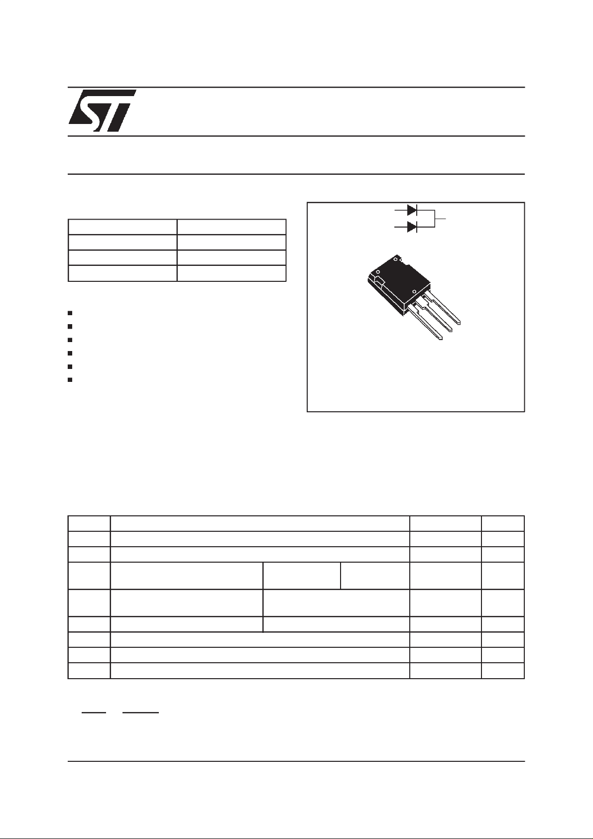
STPS80H100CY
HIGH VOLTAGE POWER SCHOTTKY RECTIFIER
PRELIMINARY DATASHEET
MAINPRODUCTCHARACTERISTICS
I
F(AV)
V
RRM
2 x 40 A
100 V
Tj (max) 175 °C
V
(max) 0.70V
F
FEATURESAND BENEFITS
HIGHREVERSEVOLTAGE
NEGLIGIBLESWITCHINGLOSSES
LOWFORWARDVOLTAGEDROP
LOWLEAKAGECURRENT
HIGHTEMPERATURE
LOWTHERMALRESISTANCE
DESCRIPTION
Dual center tap Schottky rectifier suited for
Switched Mode Power Supplies and high
frequencyDCto DCconverters.
Packaged in Max247, this device is intended for
use in high frequency computer and telecom
converters.
A1
K
A2
A2
K
A1
Max247
ABSOLUTERATINGS
(limiting values,per diode)
Symbol Parameter Value Unit
V
RRM
I
F(RMS)
I
F(AV)
I
FSM
Repetitivepeakreversevoltage 100 V
RMSforwardcurrent 50 A
Averageforwardcurrent Tc= 155°C
δ = 0.5
Surgenon repetitiveforward
tp = 10 ms sinusoidal 400 A
Perdiode
Perdevice
40
80
current
I
RRM
T
T
stg
Repetitivepeakreversecurrent tp = 2µs squareF = 1kHz 2 A
Storagetemperaturerange - 65 to + 175 °C
Maximumoperatingjunctiontemperature* 175
j
°
dV/dt Criticalrate of rise of reversevoltage 10000 V/µs
dPtot
*:
dTj
November 1999 - Ed:1B
1
<
Rth
thermal runawayconditionfor a diode on its own heatsink
(
j−a
)
A
C
1/4
Page 2
STPS80H100CY
THERMALRESISTANCES
Symbol Parameter Value Unit
R
R
th (j-c)
th (c)
Junctionto case Perdiode 0.7
Whenthe diodes 1 and 2 are used simultaneously:
∆
Tj(diode1) = P(diode1)x R
(Perdiode) + P(diode2) x R
th(j-c)
Total 0.5
Coupling 0.3
th(c)
°
C/W
STATICELECTRICAL CHARACTERISTICS
(perdiode)
Symbol Parameter Tests conditions Min. Typ. Max. Unit
I
* Reverseleakagecurrent Tj = 25°CV
R
R=VRRM
20
Tj = 125°C720mA
V
** Forwardvoltagedrop Tj = 25°CI
F
Tj = 125°CI
Tj = 25°CI
Tj = 125°CI
Pulse test : * tp = 5 ms, δ <2%
** tp = 380 µs, δ <2%
To evaluate the maximum conduction losses use the following equation :
P = 0.56 x I
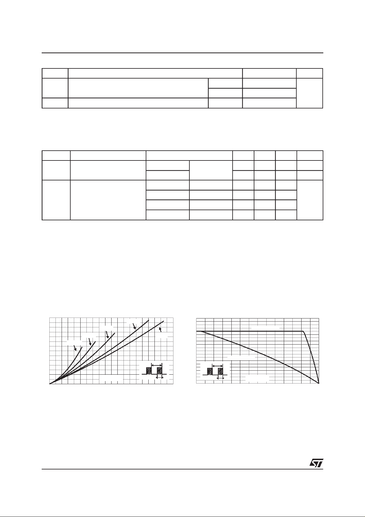
Fig. 1:
+ 0.0035x I
F(AV)
F2(RMS)
Averageforward powerdissipation versus
averageforwardcurrent(per diode).
PF(av)(W)
35
30
25
20
15
10
5
0
0 5 10 15 20 25 30 35 40 45 50
δ = 0.05
δ = 0.2
δ = 0.1
IF(av)(A)
δ= 0.5
δ
=tp/T
δ =1
T
tp
= 40A 0.8 V
F
= 40A 0.65 0.7
F
= 80A 0.94
F
= 80A 0.79 0.84
F
Fig. 2:
Average forward current versus ambient
temperature(δ=0.5, per diode).
IF(av)(A)
50
45
40
35
30
25
20
15
10
5
=tp/T
δ
0
0 25 50 75 100 125 150 175
Rth(j-a)=5°C/W
T
tp
Rth(j-a)=Rth(j-c)
Tamb(°C)
µ
A
2/4
Page 3

STPS80H100CY
Fig. 3:
Nonrepetitive surge peak forward current
versus overload duration (maximum values, per
diode).
IM(A)
500
400
300
Tc=50°C
Tc=75°C
200
IM
100
0
1E-3 1E-2 1E-1 1E+0
δ=0.5
t
t(s)
Tc=110°C
Fig. 5: Reverse leakage current versus reverse
voltageapplied (typicalvalues, per diode).
IR(µA)
1E+4
1E+3
Tj=125°C
Fig. 4:
Relative variation of thermal impedance
junctionto case versus pulse(perdiode).
Zth(j-c)/Rth(j-c)
1.0
0.8
δ = 0.5
0.6
δ = 0.2
0.4
δ = 0.1
0.2
Single pulse
0.0
1E-3 1E-2 1E-1 1E+0
tp(s)
δ
=tp/T
T
tp
Fig. 6: Junction capacitance versus reverse
voltageapplied(typical values,per diode).
C(nF)
5.0
F=1MHz
Tj=25°C
1E+2
1E+1
1E+0
1E-1
0 102030405060708090100
Tj=25°C
VR(V)
Fig. 7: Forward voltage drop versus forward
current(maximumvalues,per diode).
IFM(A)
500
100
10
1
0.0 0.2 0.4 0.6 0.8 1.0 1.2 1.4 1.6 1.8 2.0
Tj=125°C
Tj=25°C
VFM(V)
1.0
VR(V)
0.1
1 2 5 10 20 50 100
3/4
Page 4

STPS80H100CY
PACKAGEMECHANICAL DATA
Max247
REF.
DIMENSIONS
Millimeters Inches
AE
Min. Max. Min. Max.
A 4.70 5.30 0.185 0.209
A1 2.20 2.60 0.087 0.102
b 1.00 1.40 0.038 0.055
D
b1 2.00 2.40 0.079 0.094
b2 3.00 3.40 0.118 0.133
c 0.40 0.80 0.016 0.031
L1
A1
b1
L
b2
e
b
c
Orderingtype Marking Package Weight Base qty
D 19.70 10.30 0.776 0.799
e 5.35 5.55 0.211 0.219
E 15.30 15.90 0.602 0.626
L 14.20 15.20 0.559 0.598
L1 3.70 4.30 0.146 0.169
Delivery
mode
STPS80H100CY STPS80H100CY Max247 4.4g 30 Tube
Epoxymeets UL94,V0
Informationfurnishedis believed tobe accurate and reliable.However, STMicroelectronics assumes no responsibility for theconsequences of
use ofsuch informationnor for any infringementof patentsor otherrights of thirdparties which mayresult fromits use. No license is granted by
implication or otherwise under any patent or patent rights of STMicroelectronics. Specifications mentioned in this publication are subject to
change without notice. This publication supersedes and replaces all informationpreviously supplied.
STMicroelectronics products are not authorized for use as critical components in life support devices or systems without express written approval of STMicroelectronics.
The ST logo is a registeredtrademark of STMicroelectronics
1999 STMicroelectronics - Printed in Italy- All rights reserved.
Australia - Brazil - China - Finland - France - Germany - Hong Kong - India - Italy - Japan - Malaysia
Malta - Morocco - Singapore - Spain - Sweden - Switzerland - United Kingdom - U.S.A.
4/4
STMicroelectronics GROUPOF COMPANIES
http://www.st.com
 Loading...