

Page 1
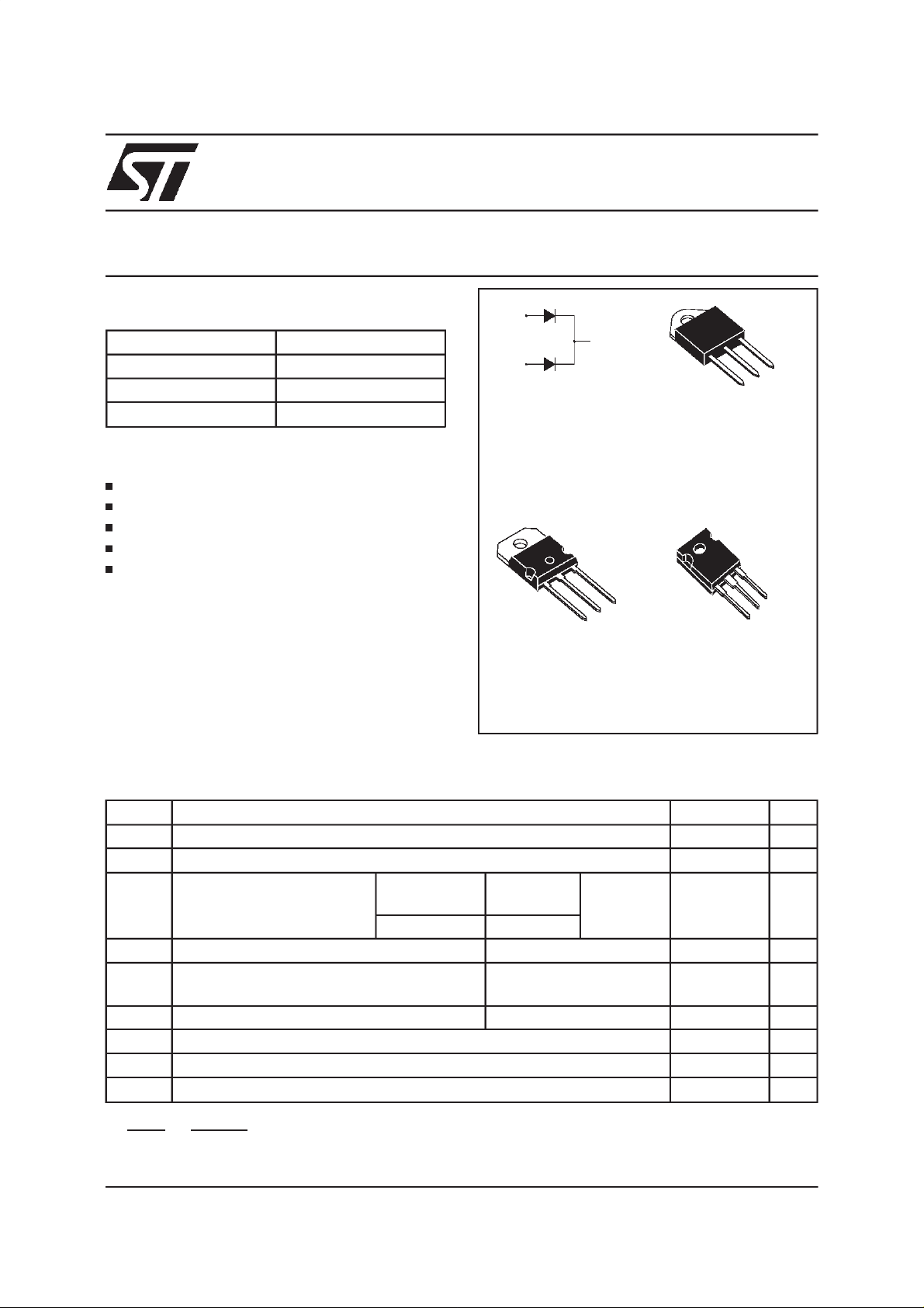
STPS6045CP/CPI/CW
POWER SCHOTTKY RECTIFIER
MAINPRODUCTCHARACTERISTICS
I
F(AV)
V
RRM
2x30 A
45 V
Tj (max) 175 °C
(max) 0.63 V
V
F
FEATURESAND BENEFITS
VERYSMALLCONDUCTION LOSSES
NEGLIGIBLESWITCHINGLOSSES
EXTREMEFAST SWITCHING
LOWTHERMALRESISTANCE
INSULATEDPACKAGE:TOP-3I
Insulatingvoltage = 2500V
RMS
Capacitance= 12pF
DESCRIPTION
Dual center tap Schottky rectifier suited for
switchmodepowersupply and high frequencyDC
toDCconverters.
Packaged either in SOT-93, TOP-3I or TO-247,
thisdeviceisintendedfor usein lowvoltage,high
frequency inverters, free wheeling and polarity
protectionapplications.
ABSOLUTERATINGS
(limiting values,per diode)
A1
A2
SOT-93
STPS6045CP
A1
K
A2
K
A1
Insulated
TOP-3I
STPS6045CPI
A2
K
A2
K
A1
TO-247
STPS6045CW
Symbol Parameter Value Unit
V
RRM
I
F(RMS)
I
F(AV)
I
FSM
I
RRM
Repetitivepeakreverse voltage
RMSforwardcurrent
Averageforwardcurrent
δ =0.5
SOT-93
TO-247
TOP-3I
Tc = 150°C Per diode
Tc = 130°C Perdevice
Surgenon repetitiveforwardcurrent tp = 10 mssinusoidal
RepetitivePeakreverse current tp = 2 µs square
45 V
60 A
30 A
60
400 A
1A
F = 1kHz
I
RSM
Tstg
Tj
dV/dt
dPtot
*:
dTj
June 1999 - Ed:5B
Non repetitivepeak reversecurrent tp = 100 µssquare
Storagetemperaturerange
Maximumoperatingjunction temperature*
Criticalrate of rise of reversevoltage
<
Rth(j−a
1
thermal runawayconditionfor adiodeon itsownheatsink
)
3A
- 65 to+ 175 °C
175 °C
10000 V/µs
1/5
Page 2
STPS6045CP/CPI/CW
THERMAL RESISTANCES
Symbol Parameter Value Unit
R
th (j-c)
Junctionto case
SOT-93/ TO-247
Perdiode
Total
TOP-3I
Perdiode
Total
R
th (c)
SOT-93/ TO-247
Coupling
TOP-3I 0.4
Whenthe diodes1 and2 are used simultaneously:
(diode1) = P(diode1)x R
∆ T
J
(Perdiode)+ P(diode2) x R
th(j-c)
th(c)
STATICELECTRICALCHARACTERISTICS (per diode)
Symbol Parameter TestsConditions Min. Typ. Max. Unit
*
I
R
V
F
Reverseleakage
current
*
Forwardvoltage drop Tj= 125°CI
Tj= 25°CV
Tj= 125°C
Tj= 25°CI
Tj= 125°CI
R=VRRM
=30A
F
=60A
F
=60A
F
0.95
°C/W
0.55
1.8
1.1
0.15
500 µA
20 80 mA
0.53 0.63 V
0.84
0.68 0.78
Pulsetest : **tp = 380 µs,
δ <2%
Toevaluate theconductionlossesuse thefollowingequation:
P= 0.48x I
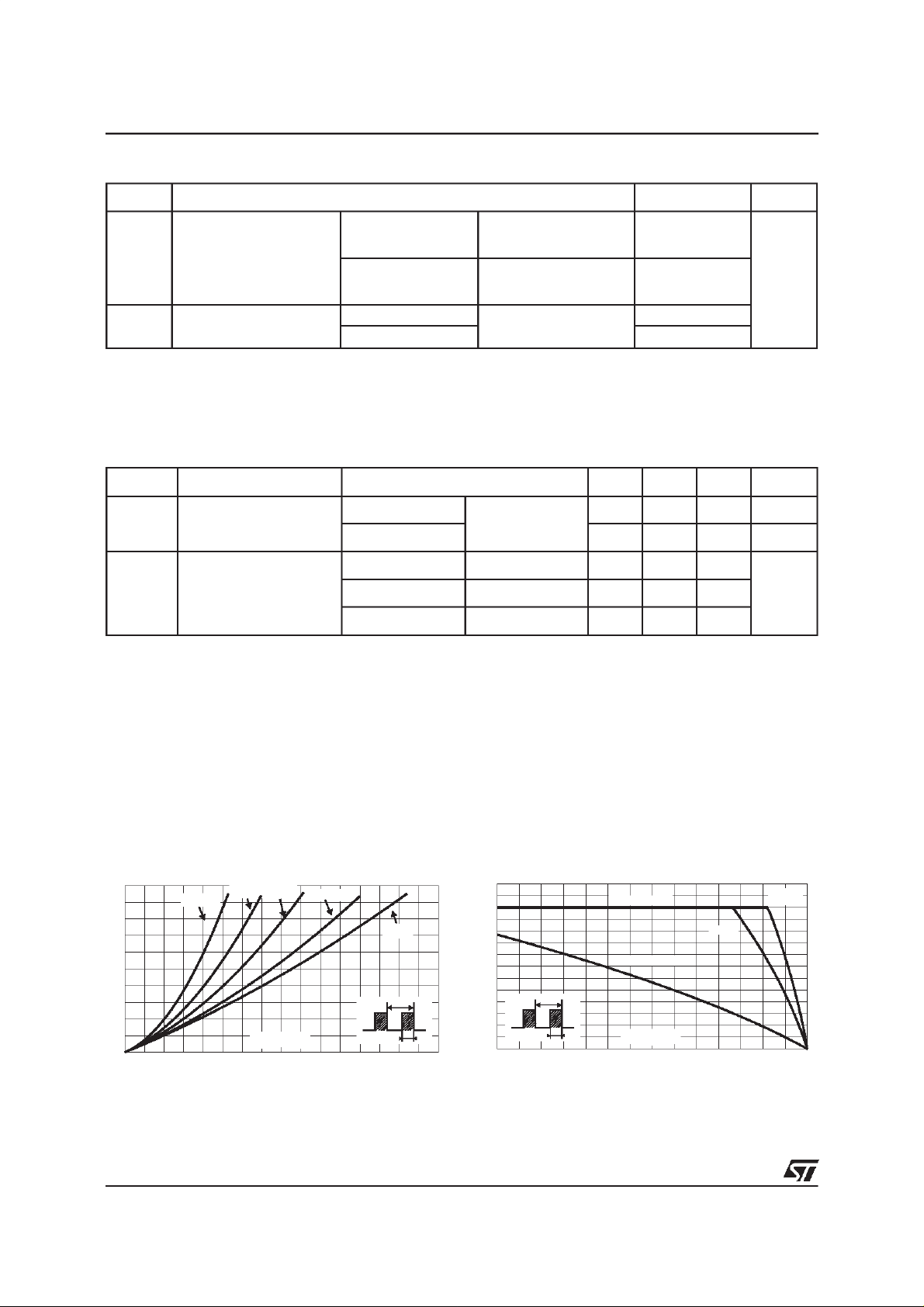
Fig. 1:
versus averageforward current(per diode).
PF(av)(W)
25
20
15
10
5
0
0 5 10 15 20 25 30 35 40
+ 0.005I
F(AV)
F2(RMS)
Average forward power dissipation
δ = 0.05
δ = 0.2δ = 0.1
IF(av) (A)
δ= 0.5
δ
=tp/T
δ =1
T
tp
Fig. 2: Average current versus ambi ent
temperature (δ=0.5 , per diode).
IF(av)(A)
35
30
25
20
15
10
5
0
0 25 50 75 100 125 150 175
δ
=tp/T
Rth(j-a)=Rth(j-c)
TOP-3I
Rth(j-a)=10°C/W
T
tp
Tamb(°C)
SOT-93
TO-247
2/5
Page 3

STPS6045CP/CPI/CW
Fig. 3-1: Non r epetitive surge peak forwar d curr ent
versus overload duration (maximum values, per
diode) (SOT-93 and TO-247).
IM(A)
350
300
250
200
150
100
IM
50
0
1E-3 1E-2 1E-1 1E+0
δ=0.5
t
t(s)
Tc=75°C
Tc=100°C
Tc=125°C
Fig. 4: Relative variation of thermal transient
impedancejunction to caseversus pulse duration.
Zth(j-c)/Rth(j-c)
1.0
0.8
δ = 0.5
0.6
0.4
δ = 0.2
δ = 0.1
0.2
Single pulse
0.0
1E-4 1E-3 1E-2 1E-1 1E+0
tp(s)
T
=tp/T tp
δ
Fig.3-2: Nonrepetitive surgepeakforwardcurrent
versus overload duration (maximum values, per
diode) (TOP-3I).
IM(A)
250
200
150
Tc=75°C
100
IM
50
0
1E-3 1E-2 1E-1 1E+0
Fig. 5:
δ=0.5
t
t(s)
Reverse leakage current versus reverse
Tc=100°C
Tc=125°C
voltageapplied(typical values,per diode).
IR(µA)
1E+5
1E+4
1E+3
1E+2
1E+1
1E+0
0 5 10 15 20 25 30 35 40 45
Tj=150°C
Tj=125°C
Tj=100°C
Tj=75°C
Tj=50°C
Tj=25°C
VR(V)
Fig. 6:
Junction capacitance versus reverse
voltageapplied (typicalvalues,per diode).
C(nF)
5.0
1.0
0.1
12 51020 50
VR(V)
F=1MHz
Tj=25°C
Fig. 7: Forward voltage drop versus forward
current(maximumvalues, per diode).
IFM(A)
200
100
10
1
0.0 0.2 0.4 0.6 0.8 1.0 1.2 1.4
Typicalvalues
Tj=125°C
Tj=25°C
Tj=125°C
VFM(V)
3/5
Page 4

STPS6045CP/CPI/CW
PACKAGEMECHANICALDATA
SOT-93
DIMENSIONS
REF.
Millimeters Inches
Min. Typ. Max. Min. Typ. Max.
A 4.70 4.90 1.185 0.193
C 1.90 2.10 0.075 0.083
D 2.50 0.098
D1 2.00 0.078
E 0.50 0.78 0.020 0.031
F 1.10 1.30 0.043 0.051
F3 1.75 0.069
F4 2.10 0.083
G 10.80 11.10 0.425 0.437
H 14.70 15.20 0.279 0.598
L 12.20 0.480
L2 16.20 0.638
L3 18.0 0.709
L5 3.95 4.15 0.156 0.163
L6 31.00 1.220
O 4.00 4.10 0.157 0.161
PACKAGE MECHANICAL DATA
TOP-3I(isolated)
DIMENSIONS
REF.
Millimeters Inches
Min. Typ. Max. Min. Typ. Max.
A 4.4 4.6 0.173 0.181
B 1.45 1.55 0.057 0.061
C 14.35 15.60 0.565 0.614
D 0.5 0.7 0.020 0.028
E 2.7 2.9 0.106 0.114
F 15.8 16.5 0.622 0.650
G 20.4 21.1 0.815 0.831
H 15.1 15.5 0.594 0.610
J 5.4 5.65 0.213 0.222
K 3.4 3.65 0.134 0.144
L 4.08 4.17 0.161 0.164
P 1.20 1.40 0.047 0.055
R 4.60 0.181
4/5
Page 5

PACKAGEMECHANICALDATA
TO-247
STPS6045CP/CPI/CW
V
REF.
Millimeters Inches
DIMENSIONS
Min. Typ. Max. Min. Typ. Max.
V
Dia.
A 4.85 5.15 0.191 0.203
D 2.20 2.60 0.086 0.102
E 0.40 0.80 0.015 0.031
F 1.00 1.40 0.039 0.055
F1 3.00 0.118
H
A
F2 2.00 0.078
F3 2.00 2.40 0.078 0.094
L5
L
L4L2
F4 3.00 3.40 0.118 0.133
G 10.90 0.429
H 15.45 15.75 0.608 0.620
L 19.85 20.15 0.781 0.793
L1 3.70 4.30 0.145 0.169
L2 18.50 0.728
F1
V2
F(x3)
G
==
F4
F3
F2
L3
L1
D
ME
L3 14.20 14.80 0.559 0.582
L4 34.60 1.362
L5 5.50 0.216
M 2.00 3.00 0.078 0.118
V5° 5°
V2 60° 60°
Dia. 3.55 3.65 0.139 0.143
Type Marking Package Weight Base qty Deliverymode
STPS6045CP STPS6045CP SOT-93 3.97g. 30 Tube
STPS6045CPI STPS6045CPI TOP-3I 4.46g. 30 Tube
STPS6045CW STPS6045CW TO-247 4.36g. 30 Tube
Coolingmethod: by conduction(C)
Recommendedtorque value:0.8 N.m.
Maximumtorquevalue: 1.0 N.m.
Epoxymeets UL94,V0
Informationfurnished is believed to be accurate and reliable. However,STMicroelectronics assumes no responsibility for the consequences of
use of such information nor forany infringementof patents or otherrights of thirdparties which mayresult fromitsuse. No license is granted by
implication or otherwise under any patent or patent rights of STMicroelectronics.Specifications mentioned in this publication are subject to
change without notice. This publication supersedes and replacesall informationpreviously supplied.
STMicroelectronics products are not authorized for use as critical components in life support devices orsystems without express writtenapproval of STMicroelectronics.
The ST logois aregistered trademark of STMicroelectronics
1999 STMicroelectronics - Printed inItaly - All rights reserved.
STMicroelectronics GROUP OFCOMPANIES
Australia -Brazil - China - Finland - France - Germany - Hong Kong - India - Italy - Japan - Malaysia
Malta - Morocco - Singapore - Spain - Sweden - Switzerland - United Kingdom - U.S.A.
http://www.st.com
5/5
 Loading...