

Page 1
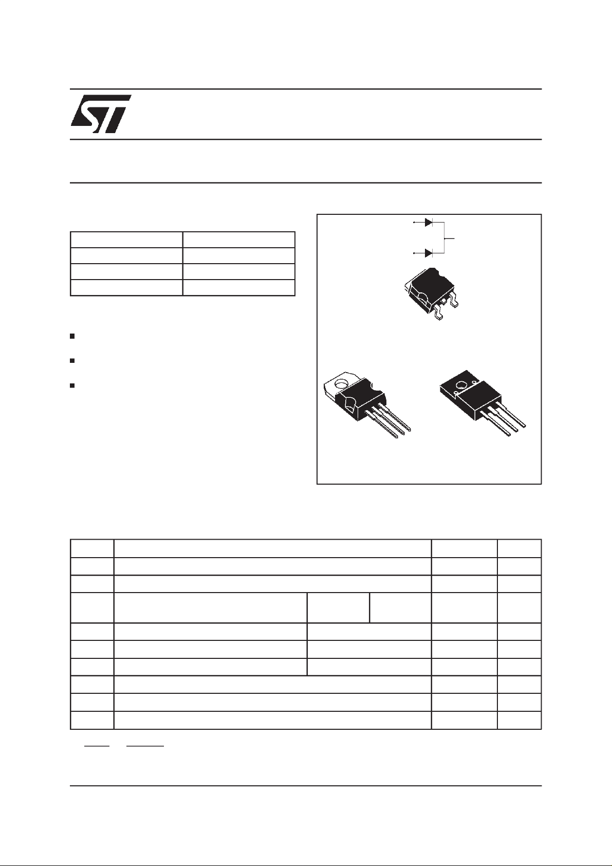
STPS10L40CT/CG/CF
LOW DROP POWER SCHOTTKY RECTIFIER
MAINPRODUCTSCHARACTERISTICS
I
F(AV)
V
RRM
2x5A
40 V
Tj (max) 150°C
(max) 0.46 V
V
F
FEATURESAND BENEFITS
LOW FORWARD VOLTAGE DROP MEANING
VERYSMALLCONDUCTIONLOSSES
LOW DYNAMIC LOSSES AS A RESULT OF
THESCHOTTKYBARRIER
AVALANCHERATED
DESCRIPTION
Dual center tap Schottky rectifiers suited for
Switched Mode Power Supplies and high
frequencyDC to DCconverters.
Packaged in TO-220AB, ISOWATT220AB and
2
D
PAK, thesedevicesare intended for use in low
voltage, high frequency inverters, free-wheeling
and polarityprotectionapplications.
A1
TO-220AB
STPS10L40CT
A1
K
A2
K
A2
A1
2
PAK
D
STPS10L40CG
A2
K
ISOWATT220AB
STPS10L40CF
A2
K
A1
ABSOLUTE RATINGS(limiting values,per diode)
Symbol Parameter Value Unit
V
RRM
I
F(RMS)
I
F(AV)
I
FSM
I
RRM
I
RSM
T
stg
Tj
dV/dt
dPtot
*:
dTj
July 1999- Ed:4A
Repetitivepeak reversevoltage
RMSforward current
Averageforwardcurrent Tc= 135°C
Surgenon repetitiveforwardcurrent tp= 10 ms Sinusoidal
Repetitivepeak reversecurrent tp=2µs squareF=1kHz
Nonrepetitive peak reversecurrent tp= 100 µs square
Storagetemperaturerange
Maximumoperating junctiontemperature *
Criticalrate of riseof reverse voltage
<
Rth(j
δ = 0.5
1
thermal runawaycondition for a diodeon its own heatsink
−
a
)
Per diode
Per device
40 V
20 A
5
10
150 A
1A
2A
- 65 to + 150 °C
150 °C
10000 V/µs
A
1/6
Page 2
STPS10L40CT/CG/CF
THERMAL RESISTANCES
Symbol Parameter Value Unit
R
R
th (j-c)
th (c)
Junctionto case TO-220AB
D
2
PAK
Perdiode
Total
Coupling 0.35
3
1.7
°C/W
R
R
th (j-c)
th (c)
Junctionto case
ISOWATT220AB
Perdiode
Total
3.8
Coupling 2.5
5
°C/W
Whenthe diodes1 and 2 areused simultaneously:
∆ Tj(diode1) = P(diode1)x R
(Per diode)+ P(diode2) x R
th(j-c)
th(c)
STATICELECTRICALCHARACTERISTICS(perdiode)
Symbol Parameter TestsConditions Min. Typ. Max. Unit
*
I
R
V
*
F
Reverseleakage
current
Forwardvoltagedrop Tj= 25°CI
Tj= 25°CV
R=VRRM
Tj= 100°C
=5A
F
Tj= 125°CI
Tj= 25°CI
Tj= 125°CI
=5A
F
=10A
F
=10A
F
825mA
0.36 0.46
0.49 0.59
0.2 mA
0.53 V
0.67
Pulsetest : * tp= 380µs, δ <2%
To evaluatethe conductionlossesuse the followingequation :
P = 0.33x I
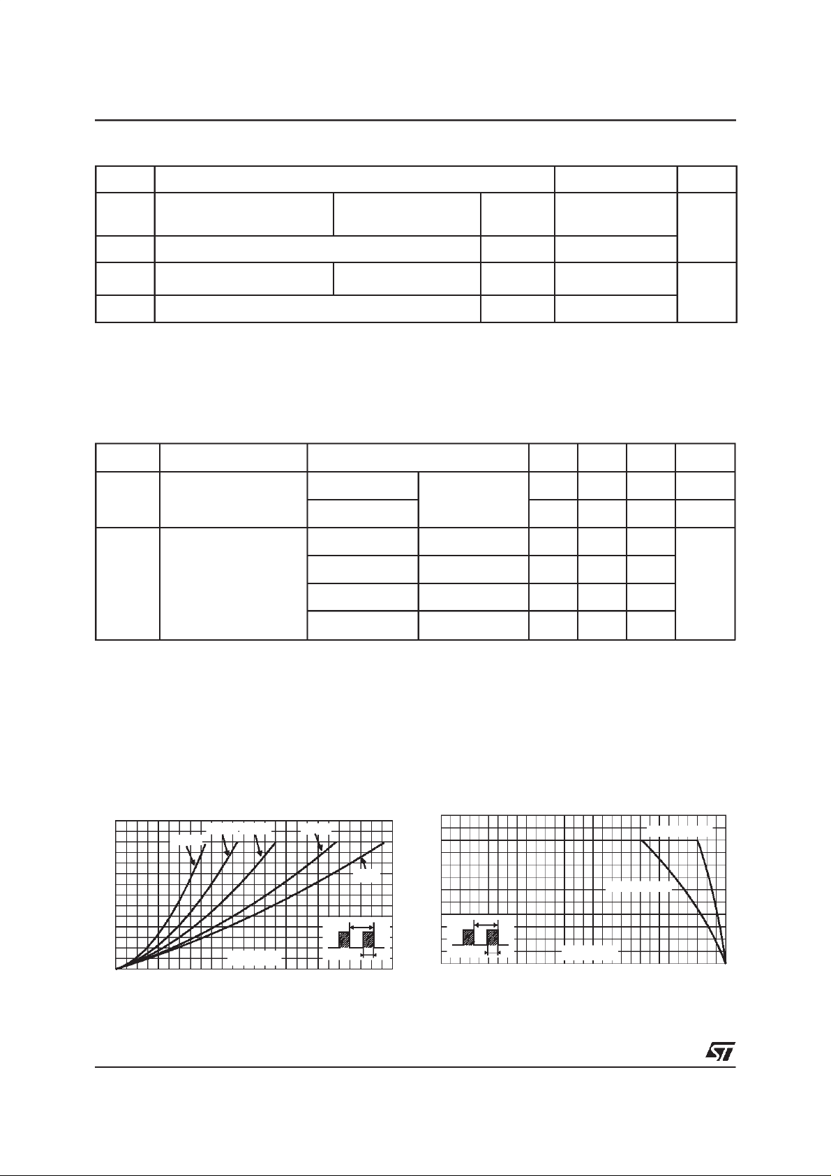
Fig. 1:
Averageforward power dissipationversus
averageforwardcurrent(per diode).
PF(av)(W)
3.5
3.0
2.5
2.0
1.5
1.0
0.5
0.0
0.0 0.5 1.0 1.5 2.0 2.5 3.0 3.5 4.0 4.5 5.0 5.5 6.0 6.5
2/6
F(AV)
δ= 0.05
+0.026 I
δ = 0.1
δ = 0.2
IF(av) (A)
F2(RMS)
δ = 0.5
δ
=tp/T
δ =1
T
Fig. 2:
temperature(δ=0.5, per diode).
IF(av)(A)
6
5
4
3
2
1
tp
0
0 25 50 75 100 125 150
Average forward current versus ambient
Rth(j-a)=Rth(j-c)
Rth(j-a)=15°C/W
T
δ
=tp/T
tp
Tamb(°C)
Page 3

STPS10L40CT/CG/CF
Fig. 3-1: Non repetitive surge peak forward
current versus overload duration (maximum
values,per diode) (TO-220ABand D
IM(A)
100
90
80
70
60
50
40
30
IM
20
10
0
1E-3 1E-2 1E-1 1E+0
δ=0.5
t
t(s)
2
PAK).
Tc=25°C
Tc=75°C
Tc=125°C
Fig. 4-1: Relativevariation of thermal impedance
junctionto case versuspulseduration.
(TO-220ABand D
Zth(j-c)/Rth(j-c)
1.0
2
PAK).
Fig. 3-2: Non repetitive surge peak forward
current versus overload duration (maximum
values,perdiode) (ISOWATT220AB).
IM(A)
80
70
60
50
40
30
20
IM
10
0
1E-3 1E-2 1E-1 1E+0
δ=0.5
t
t(s)
Tc=25°C
Tc=75°C
Tc=125°C
Fig. 4-2: Relativevariation of thermal impedance
junctionto caseversus pulseduration.
(ISOWATT220AB).
Zth(j-c)/Rth(j-c)
1.0
0.8
δ = 0.5
0.6
δ = 0.2
0.4
δ = 0.1
0.2
Single pulse
tp(s)
0.0
1E-3 1E-2 1E-1 1E+0
δ
=tp/T
T
tp
Fig. 5: Reverse leakage current versus reverse
voltageapplied (typicalvalues, per diode).
IR(mA)
1E+2
1E+1
1E+0
1E-1
1E-2
1E-3
0 5 10 15 20 25 30 35 40
Tj=150°C
Tj=100°C
Tj=25°C
VR(V)
0.8
δ = 0.5
0.6
0.4
δ = 0.2
δ = 0.1
0.2
0.0
1E-3 1E-2 1E-1 1E+0 1E+1
Fig. 6:
Single pulse
Junction capacitance versus reverse
tp(s)
δ
=tp/T
T
tp
voltageapplied (typicalvalues,per diode).
C(pF)
1000
100
VR(V)
10
12 51020 50
F=1MHz
Tj=25°C
3/6
Page 4

STPS10L40CT/CG/CF
Fig. 7: Forward voltage drop versus forward
current(maximum values,per diode).
IFM(A)
100.0
Tj=150°C
Typicalvalues
10.0
Tj=125°C
1.0
0.1
0.0 0.2 0.4 0.6 0.8 1.0 1.2 1.4 1.6 1.8
Tj=25°C
VFM(V)
PACKAGEMECHANICALDATA
TO-220AB
A
C
D
M
L2
F2
F1
H2
Dia
L5
L6
L9
L4
F
G1
G
Fig. 8: Thermal resistance junction to ambient
versus copper surface under tab (Epoxy printed
circ ui tboardFR4,copperthickn es s:35µm)(D
Rth(j-a) (°C/W)
80
70
60
50
40
30
20
10
0
0 4 8 12 16 20 24 28 32 36 40
S(Cu)
(cm )
DIMENSIONS
REF.
Millimeters Inches
Min. Max. Min. Max.
A 4.40 4.60 0.173 0.181
C 1.23 1.32 0.048 0.051
D 2.40 2.72 0.094 0.107
L7
E 0.49 0.70 0.019 0.027
F 0.61 0.88 0.024 0.034
F1 1.14 1.70 0.044 0.066
F2 1.14 1.70 0.044 0.066
G 4.95 5.15 0.194 0.202
G1 2.40 2.70 0.094 0.106
H2 10 10.40 0.393 0.409
L2 16.4typ. 0.645typ.
L4 13 14 0.511 0.551
L5 2.65 2.95 0.104 0.116
L6 15.25 15.75 0.600 0.620
E
L7 6.20 6.60 0.244 0.259
L9 3.50 3.93 0.137 0.154
M 2.6 typ. 0.102 typ.
Diam. 3.75 3.85 0.147 0.151
2
PAK).
4/6
Page 5

PACKAGEMECHANICAL DATA
2
PAK
D
E
L2
L
L3
A1
B2
B
G
C2
STPS10L40CT/CG/CF
DIMENSIONS
A
REF.
A 4.40 4.60 0.173 0.181
A1 2.49 2.69 0.098 0.106
A2 0.03 0.23 0.001 0.009
D
B 0.70 0.93 0.027 0.037
B2 1.14 1.70 0.045 0.067
C 0.45 0.60 0.017 0.024
C2 1.23 1.36 0.048 0.054
D 8.95 9.35 0.352 0.368
E 10.00 10.40 0.393 0.409
C
R
G 4.88 5.28 0.192 0.208
L 15.00 15.85 0.590 0.624
L2 1.27 1.40 0.050 0.055
L3 1.40 1.75 0.055 0.069
M 2.40 3.20 0.094 0.126
A2
R 0.40 typ. 0.016typ.
V2 0° 8° 0° 8°
Millimeters Inches
Min. Max. Min. Max.
* FLATZONE NO LESSTHAN 2mm
FOOTPRINT DIMENSIONS
16.90
10.30
8.90
M
*
(in millimeters)
1.30
3.70
V2
5.08
5/6
Page 6

STPS10L40CT/CG/CF
PACKAGEMECHANICALDATA
ISOWATT220AB
DIMENSIONS
REF.
Millimeters Inches
Min. Max. Min. Max.
A 4.40 4.60 0.173 0.181
B 2.50 2.70 0.098 0.106
D 2.50 2.75 0.098 0.108
E 0.40 0.70 0.016 0.028
F 0.75 1.00 0.030 0.039
F1 1.15 1.70 0.045 0.067
F2 1.15 1.70 0.045 0.067
G 4.95 5.20 0.195 0.205
G1 2.40 2.70 0.094 0.106
H 10.00 10.40 0.394 0.409
L2 16.00typ. 0.630typ.
L3 28.60 30.60 1.125 1.205
L4 9.80 10.60 0.386 0.417
L6 15.90 16.40 0.626 0.646
L7 9.00 9.30 0.354 0.366
Diam 3.00 3.20 0.118 0.126
Orderingtype Marking Package Weight Base qty
STPS10L40CT STPS10L40CT TO-220AB 2.23g 50 Tube
STPS10L40CG STPS10L40CG D
STPS10L40CG-TR STPS10L40CG D
2
PAK 1.48g 50 Tube
2
PAK 1.48g 1000 Tape& reel
Delivery
mode
STPS10L40CF STPS10L40CF ISOWATT220AB 2.08g 50 Tube
Coolingmethod: by conduction(C)
Recommendedtorque value : 0.55N.m.
Maximumtorquevalue : 0.70N.m.
Epoxymeets UL94,V0
Informationfurnishedis believed to be accurate and reliable. However, STMicroelectronics assumes no responsibilityfor theconsequences of
use of such informationnor forany infringementof patentsor otherrights of thirdparties which mayresult fromits use. No license is granted by
implication or otherwise under any patent or patent rights of STMicroelectronics. Specifications mentioned in this publication are subject to
change without notice. This publication supersedes andreplaces all informationpreviously supplied.
STMicroelectronics products are not authorized for use as critical components in life support devices or systems without express written approval of STMicroelectronics.
The ST logo is a registered trademark of STMicroelectronics
1999 STMicroelectronics -Printed inItaly - All rights reserved.
STMicroelectronics GROUP OF COMPANIES
Australia - Brazil - China - Finland - France - Germany - Hong Kong - India - Italy - Japan - Malaysia
Malta - Morocco - Singapore - Spain - Sweden - Switzerland - United Kingdom - U.S.A.
http://www.st.com
6/6
 Loading...