

Page 1

STK521
..............................................................................................
User Guide
8194B–AVR–01/12
Page 2

Table of Contents
Section 1 1
Introduction 1
Features 2
Section 2 3
Using the STK521 Top Module 3
Connecting the Atmel STK521 to the Atmel STK500 Starter Kit 3
Powering the STK521 4
Programming the AVR 5
Atmel AVR JTAGICE mkII Connector 7
Atmel STK521 switches configuration 9
Atmel STK521 headers 10
Atmel STK521 test points 11
Extra functions 11
Section 3 12
Troubleshooting Guide 12
Section 4 13
Technical Specifications 13
Section 5 14
Technical Support 14
Section 6 15
Complete Schematics 15
STK521 User Guide 1-2
8194B–AVR–01/12
Page 3
Section 1
Introduction
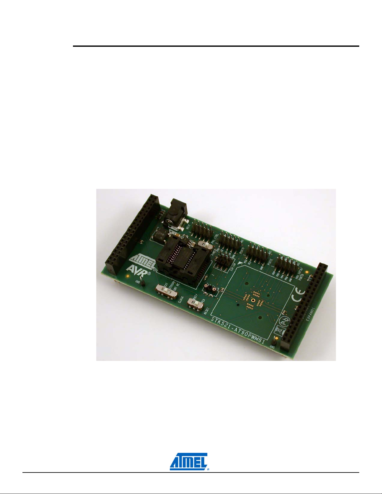
The Atmel® AVR® STK®521 kit is made of the Atmel AVR STK521 board.
The STK521 board is a top module for the Atmel STK500 development board from Atmel Corporation. It
is designed to support the Atmel AT90PWM81, Atmel AT90PWM161 products and future compatible
derivatives.
The STK521 includes connectors and hardware allowing full utilization of the new features of the
AT90PWM81/161, while the Zero Insertion Force (ZIF) socket allows easy to use of SOIC20 package for
prototyping.
This user guide acts as a general getting started guide as well as a complete technical reference for
advanced users.
Note that in this guide, the word AVR is used to refer to the target components (AT90PWM81/161).
AT90PWM81 will be also used to refer to one of the products from this family.
Figure 1-1. STK521 Top Module for STK500.
STK521 User Guide 1-1
8194B–AVR–01/12
Page 4

1.1 Features
Atmel AVR STK521 is a new member of the successful Atmel STK500 starter kit family
Supports the Atmel AT90PWM81, Atmel AT90PWM161
Supported by Atmel AVR Studio
Zero Insertion Force Socket for SOIC20 Package
Zero Insertion Force Socket for QFN32 Package (not populated)
High Voltage Parallel Programming
Serial Programming
6-pin Connector for On-chip Debugging using Atmel AVR JTAGICE mkII or Atmel AVR Dragon
Switches for Reset/GPIOs configuration, Xtal/GPIOs or power supply configuration
External power supply connector for standalone mode
Quick Reference to all Jumpers in the Silk-Screen of the PCB
emulators
®
4.15 or above and Atmel AVR Studio 5.1
™
STK521 User Guide 1-2
8194B–AVR–01/12
Page 5
Using the STK521 Top Module
2.1 Connecting the Atmel STK521 to the Atmel STK500 Starter Kit
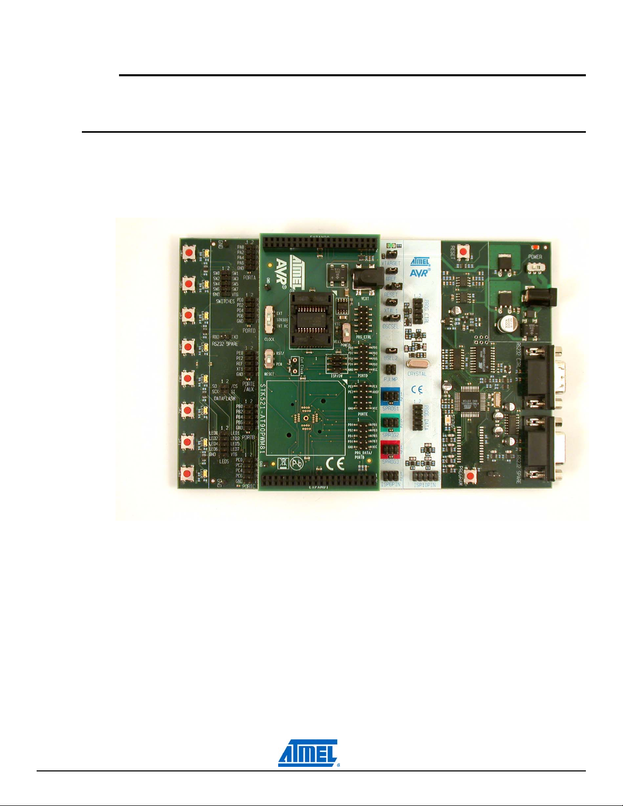
Connect the STK521 to the STK500 expansion header 0 and 1. It is important that the top module is connected in the correct orientation as shown in Figure 2-1. The EXPAND0 written on the STK521 top
module should match the EXPAND0 written beside the expansion header on the STK500 board.
Figure 2-1. Connecting STK521 to the STK500 Board.
Section 2
Note: Connecting the STK521 with wrong orientation may damage the board.
STK521 User Guide 2-3
8194B–AVR–01/12
Page 6
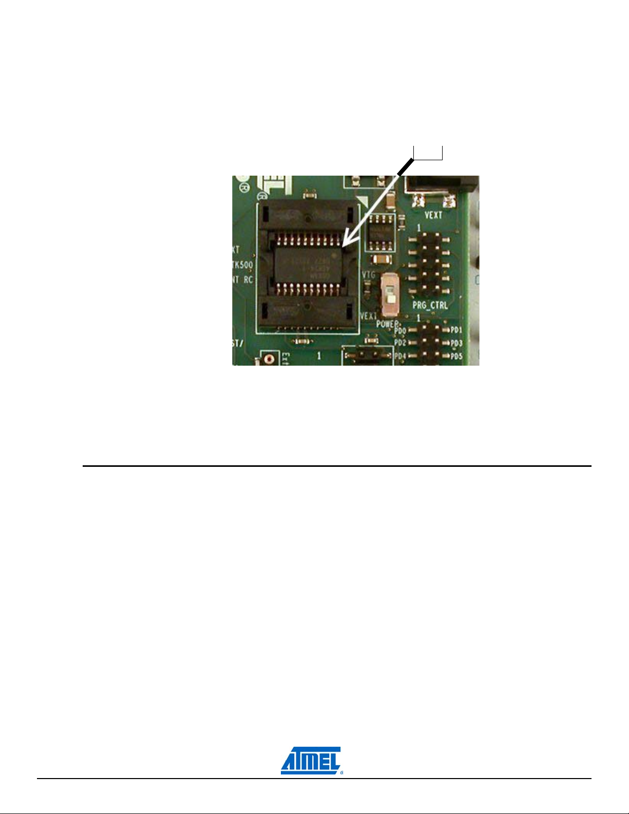
2.1.1 Placing an Atmel AT90PWM81 on the Atmel STK521
PIN1
The STK521 contains a ZIF socket for a SOIC20 package. Care should be taken so that the device is
mounted with the correct orientation. Figure 2-2 shows the location of pin1 for the ZIF socket.
Figure 2-2. Pin1 on ZIF Socket.
Caution: Do not mount an Atmel AT90PWM81 on the STK521 at the same time as an AVR is mounted
on the STK500 board. None of the devices might work as intended.
2.2 Powering the STK521
The STK521 can be powered as follows :
1. Through the STK500 by selecting POWER switch to VTG.
2. Through an external power supply using the jack connector and selecting POWER switch to
VEXT.
In this latter case, power supply must be 10V DC for a 5V device power supply.
STK521 User Guide 2-4
8194B–AVR–01/12
Page 7
2.3 Programming the AVR
The Atmel AT90PWM81 can be programmed using both serial SPI and high-voltage parallel programming. This section will explain how to connect the programming cables to successfully use one of these
two modes. The Atmel AVR Studio STK500 software is used in the same way as for other AVR parts.
Note: The AT90PWM81 also supports Self Programming, see the Atmel AVR109 application note for
more information on this topic.
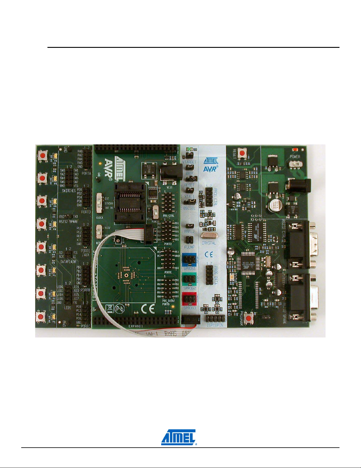
2.3.1 Serial in-system programming
Figure 2-3. Serial in-system programming.
To program the AT90PWM81 using ISP programming mode, connect the 6-wire cable between the
ISP6PIN connector on the Atmel STK500 board and the ISP connector on the Atmel STK521 board as
shown in Figure 2-3. The device can be programmed using the Serial Programming mode in the AVR
Studio 4 STK500 software.
STK521 User Guide 2-5
8194B–AVR–01/12
Page 8

The Atmel STK500 and STK521 jumpers must be configured as follows :
Table 2-1. In-System programming jumper settings for the Atmel AT90PWM81.
Note: See the Atmel STK500 User Guide for information on how to use the STK500 front-end software
for ISP Programming.
2.3.2 High-voltage programming
STK500
VTARGET Mounted
AREF Open
RESET Open
XTAL1 Mounted
OSCSEL Mounted, pin 1 and 2
BSEL2 Open
PJUMP Open
Figure 2-4. High-voltage (parallel) programming.
STK521 User Guide 2-6
8194B–AVR–01/12
Page 9

To program the AVR using high-voltage (parallel) programming, connect the PROG_CTRL of the Atmel
STK500 to PRG_CTRL of the Atmel STK521 and PROG_DATA of STK500 to PRG_DATA of STK521
as shown in Figure 2-4. Make sure that the CLOCK switch is placed in the STK500 position.
The STK500 and STK521 jumpers & switches must must be configured as follows :
Table 2-2. High-Voltage programming jumper settings for the Atmel AT90PWM81.
STK500
VTARGET Mounted
AREF Open
RESET Mounted
XTAL1 Mounted
OSCSEL Mounted, pin 1 and 2
BSEL2 Mounted
PJUMP Open
Table 2-3. High-voltage programming switches settings for AT90PWM81.
STK521
POWER VTG
CLOCK STK500
RESET RST/
The device can now be programmed using the high-voltage programming mode in the Atmel AVR Studio
STK500 software.
Note: See the Atmel STK500 User Guide for information on how to use the STK500 front-end software
in high-voltage programming mode.
For the high-voltage programming mode to function correctly, the target voltage must be higher
than 4.5V.
2.4 Atmel AVR JTAGICE mkII Connector
See the following document :
“JTAGICE mkII Quick Start Guide” which purpose is “Connecting to a target board with the AVR
JTAGICE mkII”.
This note explains which signals are required for ISP and which signals are required for debugWIRE.
Figure 2-5 shows how to connect the Atmel AVR JTAGICE mkII probe on the STK521 board.
STK521 User Guide 2-7
8194B–AVR–01/12
Page 10

Figure 2-5. Connecting the Atmel AVR JTAGICE mkII to the Atmel STK521.
PIN1
The ISP connector is used for the Atmel AT90PWM81 built-in debugWire interface. The pin out of the
connector is shown in Table 2-4 and is compliant with the pin out of the JTAG ICE available from Atmel.
Connecting a JTAGICE mkII to this connector allows on-chip debugging of the AT90PWM81.
More information about the JTAGICE mkII and on-chip debugging can be found in the Atmel AVR
JTAGICE mkII User Guide, which is available at the Atmel web site, www.atmel.com.
Note: Remove the RESET jumper on the Atmel STK500 to work run properly JTAGICE mkII.
Table 2-4. STK521 ISP/DW connector pinout.
Squid cable
colors Target pins STK521 ISP pinout Target pins
grey MISO 1 2 VTG purple
black SCK 3 4 MOSI red
green RESET 5 6 GND brown
Squid cable
colors
Note: MISO, MOSI, and SCK lines can be disconnected when the product is in debugging mode. They
can then be used for application purpose.
STK521 User Guide 2-8
8194B–AVR–01/12
Page 11

2.5 Atmel STK521 switches configuration
The switches shown in Figure 2-6 are described in Table 2-5 .
Figure 2-6. STK521 switches.
Table 2-5. STK521 switches description.
Switches Function Description
Clock source selection EXT: clock from crystal plugged in Ext Clock socket
CLOCK
RESET
POWER
Reset pin configuration RST/: Product reset pin is connected to STK500 reset button
Power supply source
selection
STK500: clock from Atmel STK500
INT RC: clock from internal RC oscillator
PE0: Product reset pin is connected to PE0 on PORTE header
VEXT: External power supply through power jack
VTG: STK500 power supply through expansion header
STK521 User Guide 2-9
8194B–AVR–01/12
Page 12

2.6 Atmel STK521 headers
High Voltage
Programmming
Interface
Port D header
Port E header
Port D header
Headers are populated for both high voltage programming purpose as well as for port connection to
LEDs or switches.
Figure 2-7. STK521 port headers.
STK521 User Guide 2-10
8194B–AVR–01/12
Page 13

2.7 Atmel STK521 test points
Table 2-6. STK521 test points.
Test Point Function Description
T1 GND GND test point
T2 GND GND test point
These are placed on both right and left side of the board for probes.
2.8 Extra functions
The STK521 includes a footprint for a ZIF QFN32 5x5 mm socket to evaluate QFN32 package. The
socket is not mounted but can be populated using the PN : QFN32(40)BT-0.5-02 from Enplas.
STK521 User Guide 2-11
8194B–AVR–01/12
Page 14

Troubleshooting Guide
Table 3-1. Troubleshooting guide.
Problem Reason Solution
Section 3
Unable to do ISP and highvoltage programming using
Internal 1MHz RC oscillator
Usage of internal 1MHz RC
oscillator not recommended
To start the microcontroller in low power
mode, use the 128KHz oscillator
STK521 User Guide 3-12
8194B–AVR–01/12
Page 15

Technical Specifications
System unit
Physical dimensions . . . . . . . . . . . . . . . . . . . . . . . . . . . . . . . . . 56mm x 119mm x 27mm
Weight . . . . . . . . . . . . . . . . . . . . . . . . . . . . . . . . . . . . . . . . . . . . . . . . . . . . . . . . . . . . . 70g
Operating conditions
Voltage supply. . . . . . . . . . . . . . . . . . . . . . . . . . . . . . . . . . . . . . . . . . . . . . . . . 1.8V - 5.5V
Temperature . . . . . . . . . . . . . . . . . . . . . . . . . . . . . . . . . . . . . . . . . . . . . . . . . . 0°C - 50°C
Section 4
STK521 User Guide 4-13
8194B–AVR–01/12
Page 16

Section 5
Technical Support
For technical support, please contact avr@atmel.com. When requesting technical support, please
include the following information:
Which target AVR device is used (complete part number)
Target voltage and speed
Clock source and fuse setting of the AVR
Programming method (ISP or high-voltage)
Hardware revisions of the AVR tools, found on the PCB
Version number of the Atmel AVR Studio. This can be found in the AVR Studio help menu
PC operating system and version/build
PC processor type and speed
A detailed description of the problem
STK521 User Guide 5-14
8194B–AVR–01/12
Page 17

Section 6
Complete Schematics
On the following pages the complete schematics and assembly drawing of the Atmel STK521 revision B
are shown.
STK521 User Guide 6-15
8194B–AVR–01/12
Page 18

Figure 6-1. Schematics, 1 of 3.
STK521 User Guide 6-16
8194B–AVR–01/12
Page 19

Figure 6-2. Schematics, 2 of 3.
STK521 User Guide 6-17
8194B–AVR–01/12
Page 20

Figure 6-3. Schematics, 3 of 3.
STK521 User Guide 6-18
8194B–AVR–01/12
Page 21

Figure 6-4. Assembly drawing, 1 of 1.
STK521 User Guide 6-19
8194B–AVR–01/12
Page 22

Atmel Corporation
2325 Orchard Parkway
San Jose, CA 95131
USA
Tel: (+1)(408) 441-0311
Fax: (+1)(408) 487-2600
www.atmel.com
Atmel Asia Limited
Unit 1-5 & 16, 19/F
BEA Tower, Millennium City 5
418 Kwun Tong Road
Kwun Tong, Kowloon
HONG KONG
Tel: (+852) 2245-6100
Atmel Munich GmbH
Business Campus
Parkring 4
D-85748 Garching b. Munich
GERMANY
Tel: (+49) 89-31970-0
Fax: (+49) 89-3194621
Atmel Japan
16F, Shin Osaki Kangyo Bldg.
1-6-4 Osaki Shinagawa-ku
Tokyo 104-0032
JAPAN
Tel: (+81) 3-6417-0300
Fax: (+81) 3-6417-0370
Fax: (+852) 2722-1369
© 2012 Atmel Corporation. All rights reserved.
®
Atmel
, Atmel logo and combinations thereof, AVR®, AVR Studio®, STK®, and others are registered trademarks or trademarks of
Atmel Corporation or its subsidiaries. Other terms and product names may be trademarks of others.
Disclaimer: The information in this document is provided in connection with Atmel products. No license, express or implied, by estoppel or otherwise, to
any intellectual property right is granted by this document or in connection with the sale of Atmel products. EXCEPT AS SET FORTH IN THE ATMEL
TERMS AND CONDITIONS OF SALES LOCATED ON THE ATMEL WEBSITE, ATMEL ASSUMES NO LIABILITY WHATSOEVER AND DISCLAIMS ANY
EXPRESS, IMPLIED OR STATUTORY WARRANTY RELATING TO ITS PRODUCTS INCLUDING, BUT NOT LIMITED TO, THE IMPLIED WARRANTY OF
MERCHANTABILITY, FITNESS FOR A PARTICULAR PURPOSE, OR NON-INFRINGEMENT. IN NO EVENT SHALL ATMEL BE LIABLE FOR ANY DIRECT,
INDIRECT, CONSEQUENTIAL, PUNITIVE, SPECIAL OR INCIDENTAL DAMAGES (INCLUDING, WITHOUT LIMITATION, DAMAGES FOR LOSS AND PROFITS, BUSINESS INTERRUPTION, OR LOSS OF INFORMATION) ARISING OUT OF THE USE OR INABILITY TO USE THIS DOCUMENT, EVEN IF ATMEL
HAS BEEN ADVISED OF THE POSSIBILITY OF SUCH DAMAGES. Atmel makes no representations or warranties with respect to the accuracy or com-
pleteness of the contents of this document and reserves the right to make changes to specifications and product descriptions at any time without notice.
Atmel does not make any commitment to update the information contained herein. Unless specifically provided otherwise, Atmel products are not suitable for, and shall not be used in, automotive applications. Atmel products are not intended, authorized, or warranted for use as components in applications intended to support or sustain life.
8194B–AVR–01/12
Page 23

Mouser Electronics
Authorized Distributor
Click to View Pricing, Inventory, Delivery & Lifecycle Information:
Atmel:
ATSTK521
 Loading...