

Page 1
SPECIFICATIONS
No.
STK442-090 2000.04.18
1. Case Outline 14Pins (See attached outline drawing)
2. Function class AB 2 channels AF power amplifier
3. Application 50W audio use
4. Maximum Ratings / Ta=25deg
5. Operating Characteristics
Tc=25deg,RL =6ohm(Non-inductive Load),Rg=600ohm,VG=30dB
*Specifications and information herein are subject to change without notice.
Note *1.1ch Drive
*2.All tests are measured using a constant-voltage supply unless otherwise specified.
*3.The output noise voltage is peak value of an average-reading meter with a rms value scale(VTVM).
A regulated AC supply(50Hz) should be used to eliminate the effects of AC primary line flicker
noise.
*4.Available time for load short-circuit and output noise voltage are measured using the specified
transformer power supply.
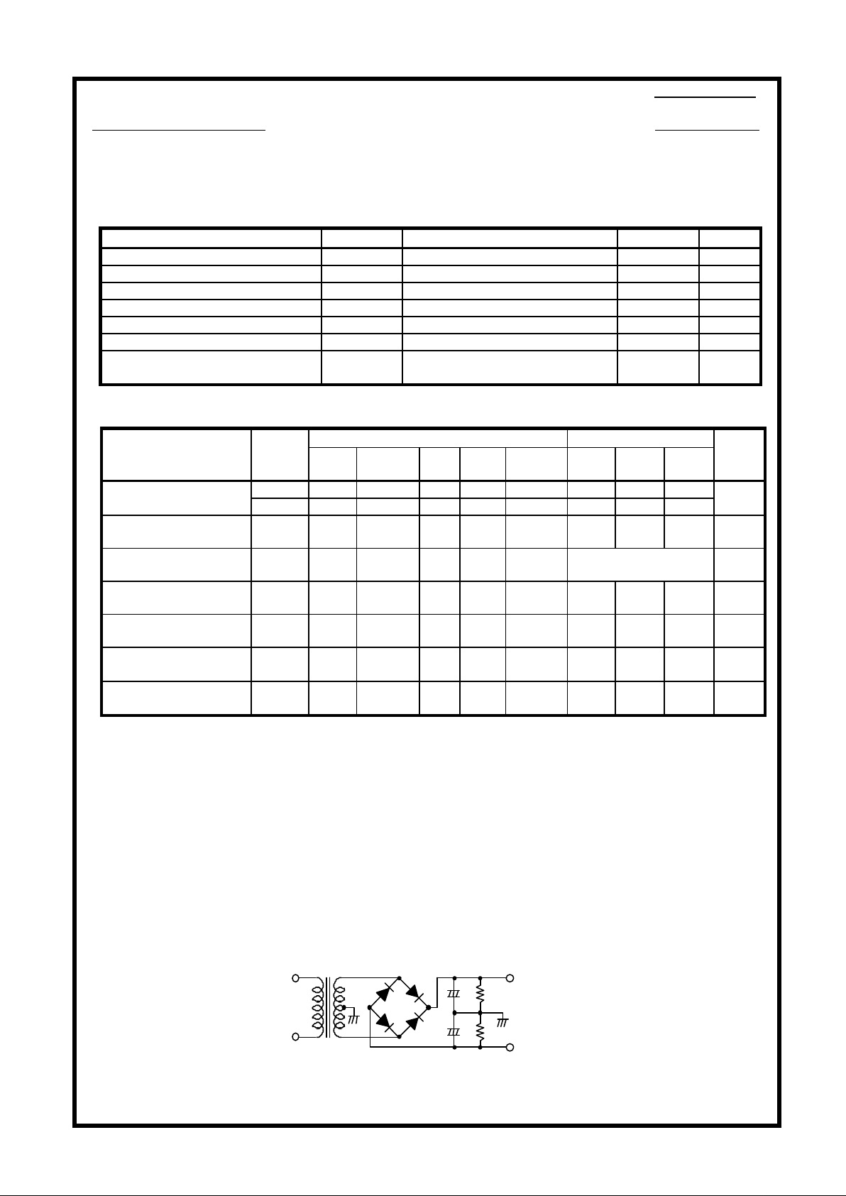
Specified Transformer Power Supply
(Equivalent to MG-200)
Item Symbol Conditions Ratings Unit
Power Supply Voltage 1 Vcc max(1) No signal
+-
54 V
Power Supply Voltage 2 Vcc max(2) Signal ,R L=8ohm ,6ohm
+-
47 V
Thermal Resistance Theta j-c Per one power TR 2.2 deg/W
Junction Temperature Tj max 150 deg
Operating Substrate Temperature Tc max 125 deg
Storage Temperature Tstg -30 to +125 deg
Available Time for Load
Short-circuit *4
ts
Vcc=+-35V,RL =6ohm,f=50Hz
P O=50W,1ch drive
0.3 s
Conditions *2 Ratings
Item Symbol
V
(V)
f
(Hz)
Po
(W)
THD
(%)
MIN. TYP. MAX.
Unit
Po1
+-
35 20 to 20k 0.4 50
Output Power *1
Po2
+-
35 1k 10 80
W
THD *1 THD +-35 20 to 20k 50
0.2 %
Frequency
Characteristics *1
fL,fH +-35 1.0 +0 -3 dB 20 to 50k Hz
Input Impedance ri +-35 1k 1.0
55 kohm
Output Noise
Voltage *3
V NO +-42
Rg=2.2
kohm
1.0 mVrms
Quiescent
Current
ICCO +-42 80 mA
Output Neutral
Voltage
V N +-42 -70 0 +70 mV
10000uDBA40C
+
+Vcc
500ohm
+
-Vcc
500ohm
10000u
Sanyo Electric Co.,Ltd. Module Systems Division NO.1
TENTATIVE
Page 2
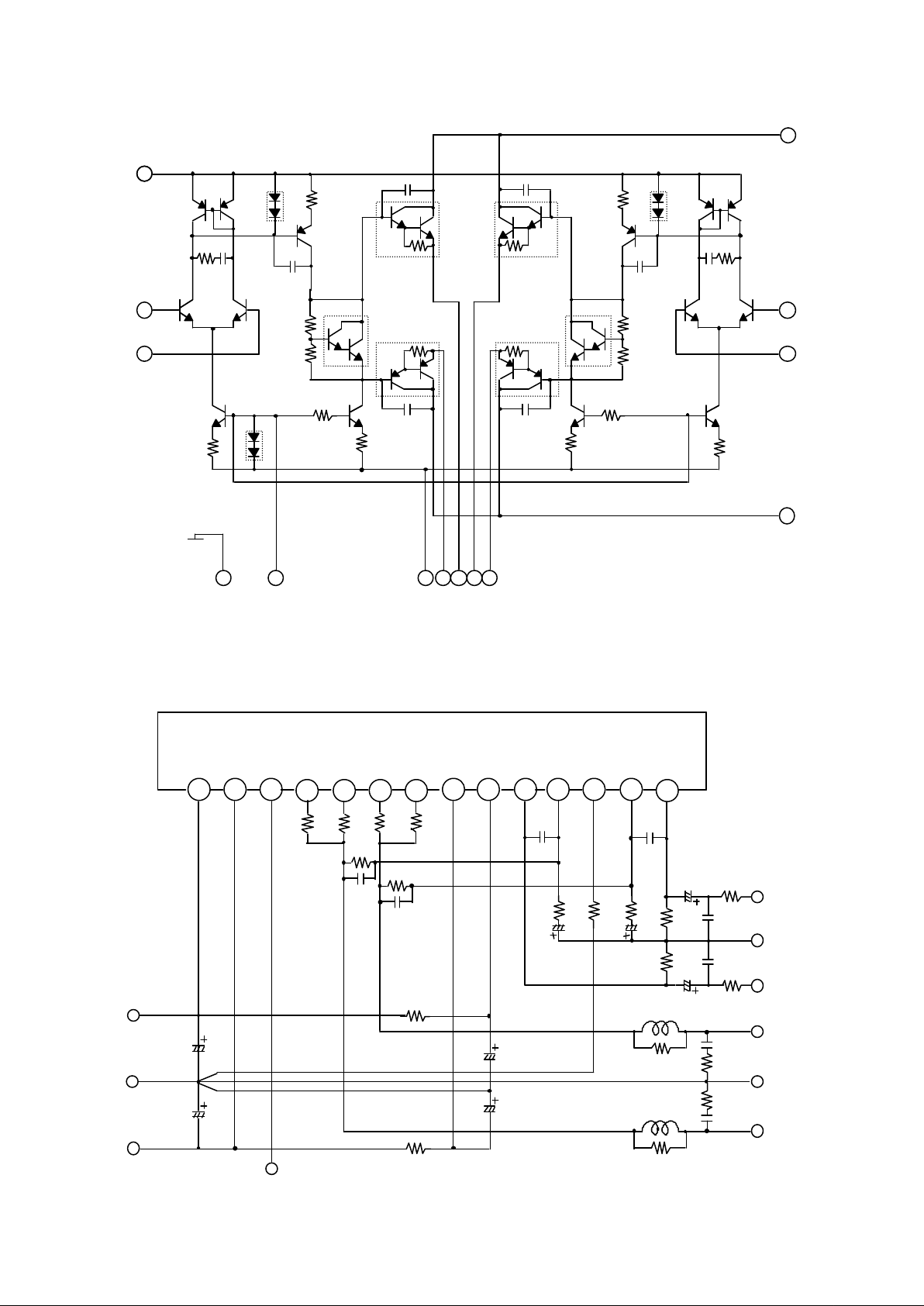
Equivalent Block Diagram
Test Circuit
TR3
TR4
TR5
TR6
TR7
TR9
TR13
TR14
TR15
TR16
TR17
TR18
TR19D1R2R4R5R6R7
R12
R14
R15
R16
R17
C1
C2
SUB
TR8
731
2
6
4
5
8
12
11109
R3
R13
TR1
TR2D2D3
TR12
TR11
TR10
TR20
13
14
C4R8C5
R18
C7C8C10
C11
(*1)Metal Plate Cement Resistor 0.22ohm+-10%(5W)
No.2
SUB.GND
GND
+Vcc
1 2 3 4 5 6 7 8 9 10 11 12 13 14
100uF
/100v
100uF
/100v
100ohm/1W
100uF
/100v
100uF
/100v
1.8kohm
1.8kohm
56kohm
3pF
56kohm
3pF
100uF
/10v
20kohm
100uF
/10v
Ch2 OUT
Ch1 OUT
GND
3uH
3uH
4.7ohm
4.7ohm/1W
4.7ohm
4.7ohm/1W
0.1uF
220pF
Ch2 IN
GND
Ch1 IN
56kohm
56kohm
470pF
470pF
2.2uF
/50v
2.2uF
/50v
1kohm
1kohm
220pF
(*1)
0.1uF
100ohm/1W
-Vcc
+ Vcc
Ch1
IN
Ch1
NF
Ch2
IN
Ch2
NF
Ch2
+RE
Ch2
-RE
Ch1
+RE
Ch1
-RE
-Vcc
SUB
-PRE
+PRE
BIAS
(*1)
(*1)
(*1)
Page 3

Case Outline
Unit:mm
This catalog provides information as of April,2000. Specifications and information herein are subject to change without notice.
No.3
* No production described or contained herein are intended for use in surgical implants, life-support
systems, aerospace equipment, nuclear power control systems, vehicles, disaster/crime-prevention
equipment and the like, the failure, of which may directly or indirectly cause injury, death or property loss
* Anyone purchasing any products described or contained herein for an above-mentioned use shall:
1. Accept full responsibility and indemnify and defend SANYO ELECTRIC CO.,LTD., its affiliates, subsidiaries and
distributors and all their officers and employees, jointly and severally, against any and all claims and litigation and all
damage, cost and expenses associated with such use:
2. Not impose any responsibility for any fault or negligence which may be cited in any such claim or litigation on
SANYO ELECTRIC CO.,LTD., its affiliates, subsidiaries and distributors or any of their officers and employees jointly or
severally.
* Information (including circuit diagrams and circuit parameters) herein is for example only ; it is not guaranteed
for volume production. SANYO believes its use or any infringements of intellectual property rights or other
rights of third parties.
 Loading...