

Page 1
θ
Ordering number: EN 1228C
°
°
°
−
°
8
Thick Film Hybrid IC
STK4352
AF Power Amplifier
(7W + 7W min, THD = 1.0%)
Features
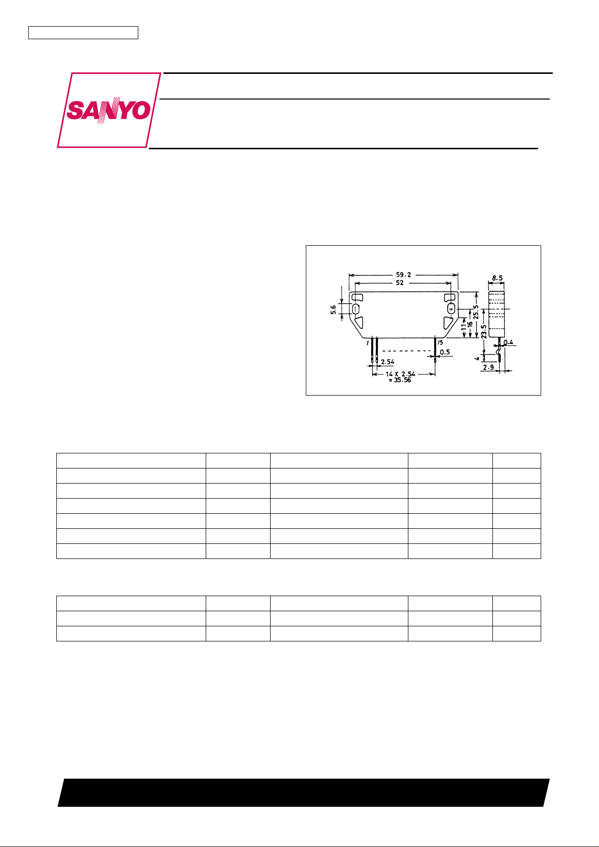
• Small and slim package with 25.5mm height.
• Capable of guaranteeing substrate temperature 125 ° C,
thereby reducing heat sink.
Package Dimensions
unit: mm
4032
[STK4352]
• Excellent cost performance.
Specifications
Maximum Ratings
Parameter Symbol Conditions Ratings Unit
Maximum supply voltage V
Thermal resistance
Junction temperature Tj 150
Operating substrate temperature T
Storage temperature Tstg
Available time for load short-circuit t
at Ta = 25 ° C
max Pin 4 to 7, 12 39 V
CC
j-c One power transistor 7
C
30 to +125
V
= 27V, R
s
CC
= 8 Ω , Po = 7W, f = 50Hz 2 s
L
125
C/W
C
C
C
Recommended Operating Conditions
Parameter Symbol Conditions Ratings Unit
Recommended supply voltage V
Load resistance R
CC
L
SANYO Electric Co., Ltd. Semiconductor Business Headquarters
TOKYO OFFICE Tokyo Bldg., 1-10, 1 Chome, Ueno, Taito-ku, TOKYO, 110 JAPAN
at Ta = 25 ° C
27 V
Ω
61197HA (ID) / 8058MO / 2033KI, TS No. 1228—1/6
Page 2
Ω
STK4352
Operating Characteristics
at Ta = 25 ° C, V
= 27V, R
CC
= 8 Ω , Rg = 600 Ω , VG = 40dB, at specified Test
L
Circuit (based on Sample Application Circuit).
Parameter Symbol Conditions min typ max Unit
Quiescent current I
Output power
Total harmonic distortion THD Po = 0.1W, f = 1kHz 0.5 %
Frequency response f
Input impedance r
Output noise voltage V
Notes. Unless otherwise specified for the power supply at the time of test, use the
constant voltage power supply.
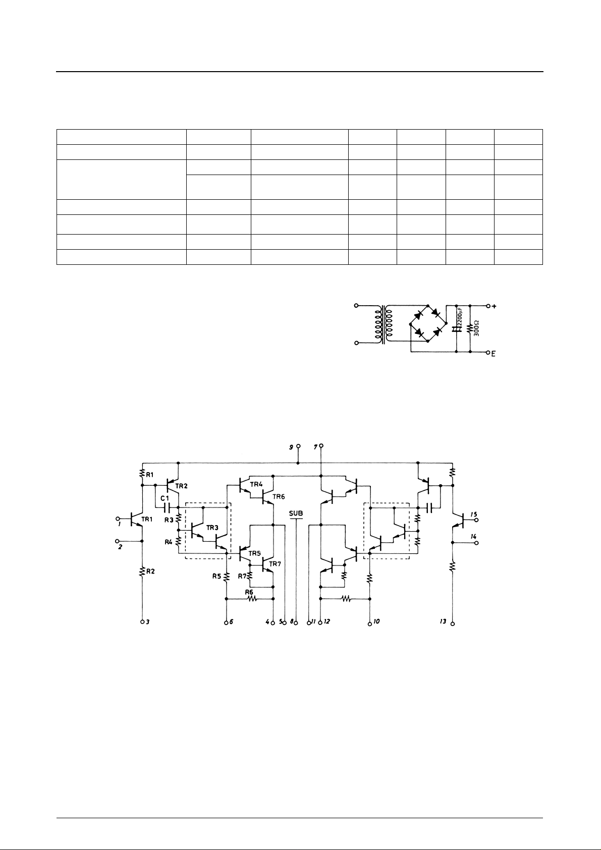
When testing the available time for load short-circuit and output noise voltage, use the specified transformer as shown right.
The output noise voltage is the peak value on the mean value indicating
rms reading (VTVM), and should not involve impulse noise.
CCO
P
(1) THD = 1.0%, f = 1kHz 7 W
O
P
(2)
O
, f
L
H
i
NO
V
= 33V 20 60 120 mA
CC
THD = 1.0%,
f = 40Hz to 20kHz
Po = 0.1W, dB 40 to 50k Hz
Po = 0.1W, f = 1kHz 110k
V
+0
−
3
= 33V, Rg = 10k Ω
CC
3.5 W
0.8 mVrms
Specified Transformer Power Supply
(Equivalent to RP-22)
Equivalent Circuit
No. 1228—2/6
Page 3
STK4352
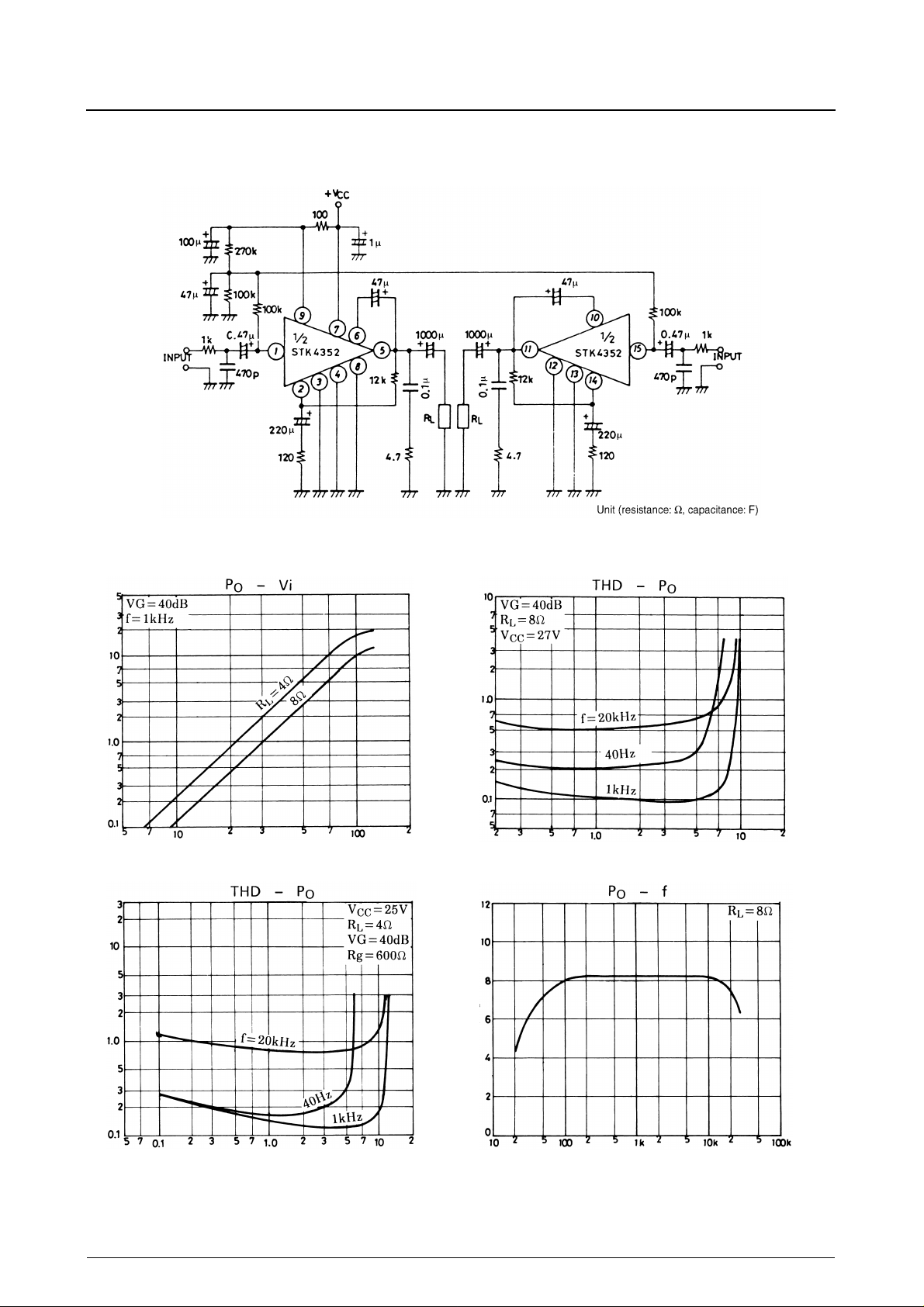
Sample Application Circuit:
7W min 2-channel AF power amplifier
Output power, Po - W
Total harmonic distortion, THD - %
Total harmonic distortion, THD - %
Inoput voltage, Vi - mV Output power, Po - W
Output power, Po - W
Output power, Po - W Frequency, f - Hz
No. 1228—3/6
Page 4
STK4352
Voltage gain, VG - dBInput impedance, r
Frequency, f - Hz
- kΩQuiescent current, Icco - mA
i
Frequency, f - Hz
Voltage gain, VG - dBOutput power, Po - W
Frequency, f - Hz
- A
CC
Quiescent current, Icco - mACurrent drain, I
Supply voltage, V
CC
- V
Supply voltage, V
CC
- V
- mVrms
- V
Quiescent current, Icco - mANeutral voltage, V
NO
N
Output noise voltage, V
Power supply ripple voltage, Vrp - mVrms
No. 1228—4/6
Page 5
STK4352
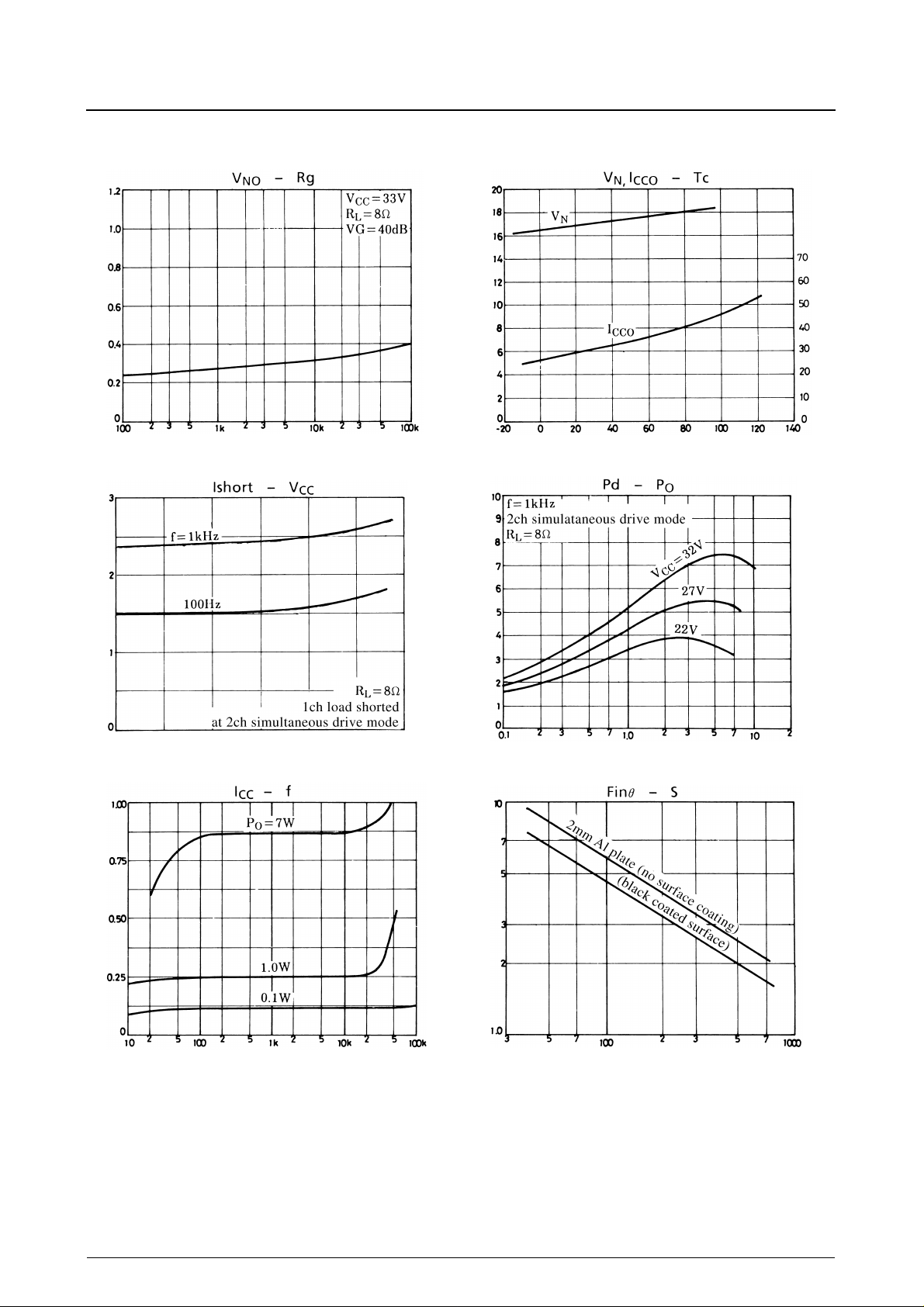
- mVrmsLoad Short current, Ishort - ACurrent drain, I
NO
Output noise voltage, V
Signal source resistance, Rg - Ω
- V
N
Neutral voltage, V
IC Power dissipation, Pd - WThermal resistance of heat sink, θ - °C/W
Quiescent current, Icco - mAQuiescent current, Icco - mA
Operating substrate temperature, Tc - ° C
Supply voltage, V
CC
- V
Output power, Po - W
- A
CC
Frequency, f - Hz
Area of heat sink, S - cm
2
No. 1228—5/6
Page 6
STK4352
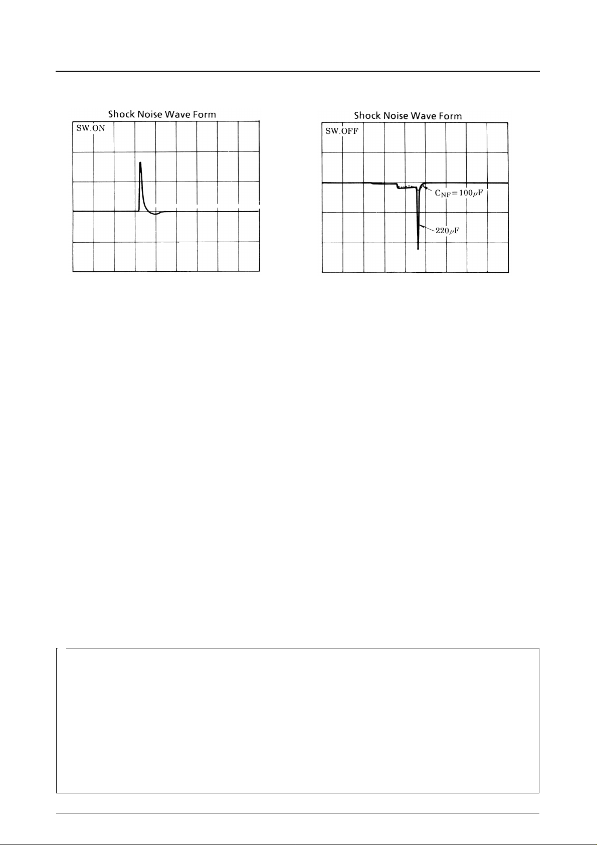
0.2V / div
0.5s / div
1V / div
0.5s / div
No products described or contained herein are intended for use in surgical implants, life-support systems, aerospace equipment, nuclear
■
power control systems, vehicles, disaster/crime-pre v ention equipment and the lik e, the failure of which may directly or indirectly cause injury,
death or property loss.
■
Anyone purchasing any products described or contained herein for an above-mentioned use shall:
➀
Accept full responsibility and indemnify and defend SANYO ELECTRIC CO., LTD., its affiliates, subsidiaries and distributors and all their
officers and employees, jointly and severally, against any and all claims and litigation and all damages, cost and expenses associated
with such use:
➁
Not impose any responsibility for any fault or negligence which may be cited in any such claim or litigation on SANYO ELECTRIC CO.,
LTD., its affiliates, subsidiaries and distributors or any of their officers and employees, jointly or severally.
■
Information (including circuit diagrams and circuit parameters) herein is for e xample only; it is not guaranteed for volume production. SANYO
believes information herein is accurate and reliable, but no guarantees are made or implied regarding its use or any infringements of
intellectual property rights or other rights of third parties.
This catalog provides information as of June, 1997. Specifications and information herein are subject to change without notice.
No. 1228—6/6
 Loading...