

Page 1

POWER LINE FSK TRANSCEIVER
■ HALF DUPLEX FREQUENCY SHIFT KEYING
(FSK) TRANSC EIVER
■ INTEGRATED POWER LINE DRIVER WITH
PROGRAMMABLE VOLTAGE AND CURRENT
CONTROL
■ PROGRAMMABLE INTERFACE:
– SYNCHRONOUS
– ASYNCHRONOUS
■
SINGLE SU PPLY VOLTA GE (FR OM 7.5 UP TO 12.5V)
■
VERY LOW POWER CONSUMPTION (I q=5 mA)
■ INTEGRATED 5V VOLTAGE REGULATOR
(UP TO 100mA) WITH SHORT CIRCUIT
PROTECTION
■ 8 PROGRAMMABLE TRANSMISSION
FREQUENCIES
■
PROGRAMMABLE BAUD RATE UP TO 4800BPS
■ RECEIVING SENSITIVITY 1 mVRMS
■
SUITABLE TO APPLICATION IN ACCORDANCE
WITH EN 50065 CENELEC SPECIFICATIONS
■ CARRIER OR PREAMBLE DETECTION
■ BAND IN USE DETECTION
■ PROGRAMMABLE REGISTER WITH
SECURITY CHECKSUM
■ MAINS ZERO CROSSING DETECTION AND
SYNCHRONIZATION
ST7538
TQFP44 Slug Down
ORDERING NUMBER: ST7538P
■ WATCHDOG T IME R
DESCRIPTION
The ST7538 is a Half Duplex synchronous/asynchronous FSK Modem designed for power line
communication network applications. It operates
from a single supply voltage an d integrates a l ine
driver and a 5V linear regulator. The device operation is controlled by means of an internal register,
programmable through the syn chronous serial interface. Additional functions as watchdog, clock
output, output voltage and current control, preamble detection, time-out, band in use are i ncluded.
Realized in Multipower BCDV technology that allows to integrate DMOS, Bipolar and CMOS structures i n the same ch ip .
BLOCK DIAGRAM
CD/PD
RxD
CLR/T
REG/DA TA
RxTx
TxD
REGOK
September 2003
INTERFACE
XOut WD TOUT RSTO MCLK ZCin ZCout C_OUT CMINUS CPLUSXIn
SERIAL
CARRIER
DETECTION
PLL
TIME BASE
DIGITAL
FILTER
CONTROL
REGISTER
FSK
MODULAT OR
TEST
FSK
DEMODIFFILTER
DAC
ZCOSC
TEST3TEST1AVddDVdd AVssDVss BU
TX
FILTER
OP-AMP
+
-
RxFoTEST2
BU
FILTER
ALC
AGC
AMPL
CURRENT
CONTROL
VOLTAGE
CONTROL
PLI
VREG
FILTER
RAI
CL
Vsense
ATO
AT OP1
AT OP2
PAVcc
Vdc
PG
D03IN1407
1/30
Page 2

ST7538
PIN CONNECTION (Top vi ew)
CD_PD
DVSS
RXD
RxTx
TXD
GND
TOUT
CLR/T
BU
DVDD
MCLK
C_MINUS
C_PLUS
N.C.
C_OUT
GND
PG
REG_DATA
N.C.
44 43 42 41 3940 38 37 36 35 34
1
2
3
4
5
6
7
8
9
10
12 13 14 15 16
171118 19 20 21 22
TEST1
REG_OK
N.C.
33
32
31
30
29
28
27
26
25
24
23
VDC
RAI
RXFO
TEST2
VSENSE
AVDD
XIN
XOUT
SGND
ATO
CL
RSTO
WD
TEST3
ZCIN
ZCOUT
N.C.
DVSS
ATOP1
PAVSS
ATOP2
D01IN1312
PAVCC
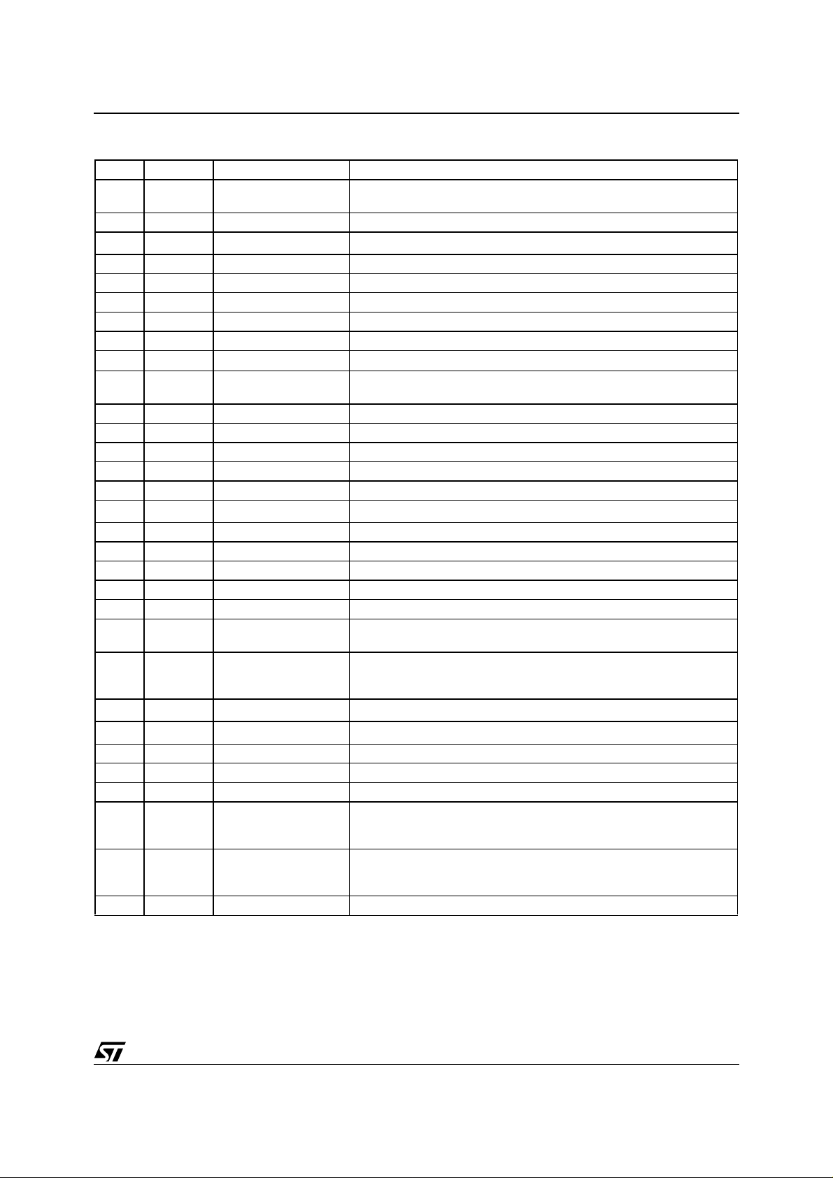
PIN DESCRIPTION
N° Name Type Description
1 CD_PD Digital/Output Carrier or Preamble Detect Output.
"1" No Carrier or Preamble Detected
"0" Carrier or Preamble Detected
2 DVss Supply Digital Ground
3 RxD Digital/Output RX Data Output.
4 RxTx Digital/Input
with internal pull-up
5 TxD Digital/Input
with internal pull-down
6 GND Supply Substrate Ground (same function as PIN 41)
7 TOUT Digital/Output TX Time Out Event Detection
8 CLR/T Digital/Output Synchronous Mains Access Clock or
9 BU Digital/Output Band in use Output.
10 DVdd Su pply Digital Supp ly Voltage
11 MCLK Digital/Output Master Clock Output
12 RSTO Digital/Output Power On or Watchdog Reset Output
13 TEST 3 Digital/Input
with internal pull-down
Rx or Tx mode selection input.
"1" - RX Session
"0" - TX Session
TX Data Input.
"1" - Time Out Event Occurred
"0" - No Time-out Event Occurred
Control Register Access Clock
"1" Signal within the Programmed Band
"0" No Signal within the Programmed Band
Test Input. Must be connected to DVss during Normal Operation
2/30
Page 3
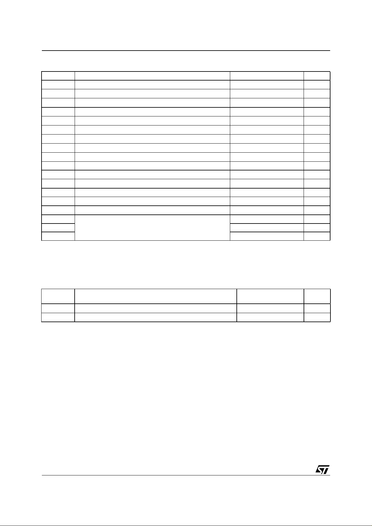
PIN DESCRIPTION (continued)
N° Name Type Description
14 WD Digital/Input
with internal pull-up
15 ZCOUT Digital/Output Zero Crossing Detection Output
16
ZCIN
1
Analog/Input Zero Crossing AC Input.
17 NC Floating Must be connected to DVss.
18 DVss Supply Digital Ground
19 ATOP1 Power/Output Power Line Driver Output
20 PAVss Supply Power Analog Ground
21 ATOP2 Power/Output Power Line Driver Output
22 PAV
23
CL
Supply Power Supply Voltage
CC
2
Analog/Input Current Limiting Feedback.
24 ATO Analog/Output Small Signal Analog Transmit Output
25 SGND Supply Analog Signal Ground
26 XOUT Analog I/O Crystal Output- External Clock Input
27 XIN Analog Input Crystal Oscillator Input
28 AVdd Supply Analog Power supply.
29
Vsense
3
Analog/Input Output Voltage Sensing input for the voltage control loop
30 TEST2 Analog/Input Test Input must be connected SGND
31 RxFO Analog/Output Receiving Filter Output
32 RAI Analog/Input Receiving Analog Input
33 VDC Power 5V Voltage Regulator Output
34 NC floating Must Be connected to DVss.
35 TEST1 Digital/Input
with internal pull-down
36 REGOK Digital/Output Security checksum logic output
37
38
C_MINUS
C_PLUS
4
Analog/Input Op-amp Inverting Input.
5
Analog/Input Op-amp Not Inverting Input.
39 NC floating Must Be connected to DVss
40 C_OUT Analog/Output Op-amp Output
41 GND Supply Substrate Ground (same function as PIN 6)
42 PG Digital/Output Power Good logic Output
43
REG_DATA
Digital/Input
with internal pull-down
44 NC floating Must be connected to DVss.
<1> If not used this pin must be connected to VDC
<2> Cannot be left floating
<3> Cannot be left floating
<4> If not used this pin must be connected to VDC
<5> If not used this pin must be tied low (SGND or PAVss or DVss)
Watchdog input. The Internal Watchdog Counter is cleared on the
falling edges.
A resistor between CL and AVss sets the PLI Current Limiting Value
Test input. Must Be connected to DVss.
"1" - Stored data Corrupted
"0" - Stored data OK
"1" - VDC is above 4.5V
"0" - VDC is below 4.25V
Mains or Control Register Access Selector
"1" - Control Register Access
"0" - Mains Access
ST7538
3/30
Page 4
ST7538
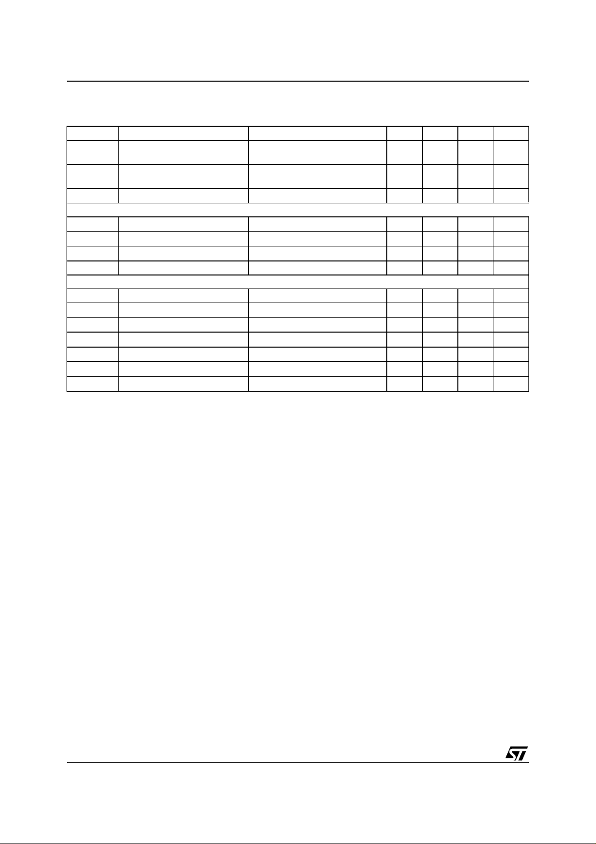
ABSOLUTE MAXIMUM RATINGS
Symbol Parameter Value Unit
PAV
AV
DV
AV
/DVss Voltage between AVss and DVss -0.3 to +0.3 V
ss
V
V
O
I
O
V
sense
RAI Voltage Range at RAI Input -AV
ATO Output Current at ATO Output -2 to +2 mA
ATO Voltage range at ATO Output AV
ATOP1,2 Voltage range at Powered ATO Output AV
ATOP Powered ATO Output Current 400 mARms
T
amb
T
stg
ATOP1 Pin Maximum Withstanding Voltage Range
ATOP2 Pin ±1000 V
Other pins ±2000 V
Power Supply Voltage -0.3 to +14 V
CC
Analog Supply Voltage -0.3 to +5.5 V
dd
Digital Supply Voltage -0.3 to +5.5 V
dd
Digital input Voltage DVss - 0.3 to DVdd +0.3 V
I
Digital output Voltage DVss - 0.3 to DVdd +0.3 V
Digital Output Current -2 to +2 mA
Voltage Range at Vsense Input AVss - 0.3 to AVdd+0.3 V
- 0.3 to AVdd +0.3 V
dd
- 0.3 to AVdd +0.3 V
ss
- 0.3 to +PAVcc +0.3 V
ss
Operating ambient Temperature -40 to +85 °C
Storage Temperature -50 to 150 °C
±1500 V
Test Condition: CDF-AEC-Q100-002- “Human Body Model”
Acceptance Criteria: “Normal Performance”
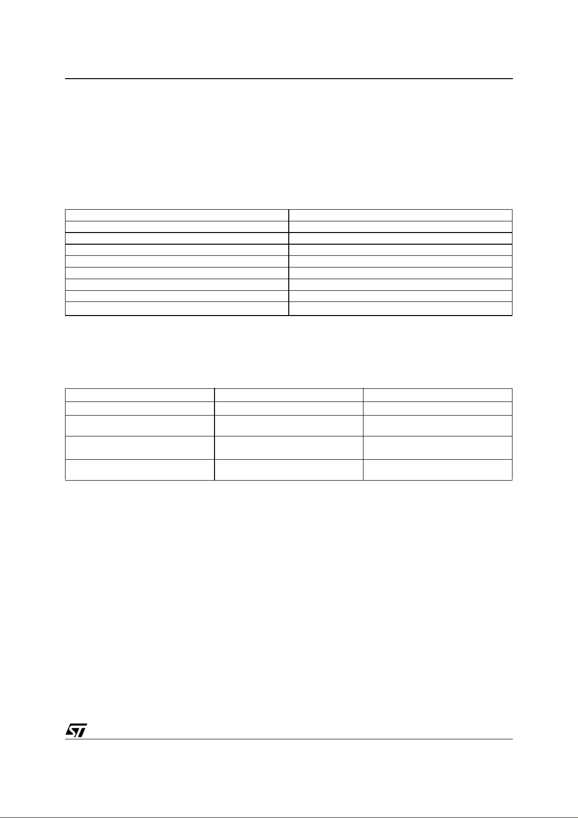
THERMA L D ATA
Symbol Parameter
R
th-j-amb1
R
th-j-amb2
(*) Mou nted on Mu l t i l a y e r P CB with a dissipating sur face on th e bo t tom sid e of the PCB
(**) It's the s am e conditio n of the point ab ove, withou t any heatsi nking surface on the board.
Maximum Thermal Resistance Junction-Ambient Steady State(*) 35 °C/W
Maximum Thermal Resistance Junction-Ambient Steady State(**) 50 °C/W
TQFP44
with slug
Unit
4/30
Page 5

ST7538
ELECTRICAL CHARACTERISTCS
(AVcc = DVcc = +5V, PAVcc =+9 V, PAVss, SGND = DVss = 0V,-40°C ≤ Tamb ≤ 85°C, unless otherwise specified)
Symbol Parameter Test Condition Min. Typ. Max. Unit
AV
,
Supply Voltages 4.75 5 5.25 V
CC
DV
CC
PAVCC - DVCCPAVCC and DVCC Relation
during Power-Up Sequence
PAVCC - AVCCPAVCC and DVCC Relation
during Power-Up Sequence
PAV
Power Supply Voltage 7.5 12.5 V
cc
Max allowed slope during
Power-Up
AICC + DICC Input Supply Current Transmission & Receiving mode 5 7 mA
I PAV
Powered Analog Supply
CC
Current
Digital I/O
V
V
V
OH
V
OL
High Logic Level Input Voltage 2 V
IH
Low Logic Level input Voltage 0.8 V
IL
High Logic Level Output Voltage IOH= -2mA 3.5 V
Low Logic Level Output Voltage IOL= 2mA 0.4 V
Oscillator
V
IHX
V
ILX
XIN High Level Input Voltage External Clock 3 V
XIN Low Level Input Voltage External Clock 2 V
DC XTAL Clock Duty Cycle External Clock 40 60 %
Xtal Crystal Oscillator frequency 16 MHz
Tclock Oscillator Period (1/Xtal) 62.5 ns
Xtal
External Oscillator Esr
ESR
Resistance
Xtal
External Oscillator Stabilization
CL
Capacitance
Transmitter
IATOP Output Transmitting Current in
programmable current limiting
V
V
ATODC
HD2
ATO
Max Carrier Output AC Voltage RCL = 1.85kΩ Vsense=0V 1.75 2.3 3.5 V
Output DC Voltage on ATO 1.7 2.1 2.5 V
Second Harmonic Distortion on
ATO
ATO
HD3
Third Harmo nic Distortion on
ATO
ATO
V
ATOP (AC)
Max Carrier Output AC Voltage
for each ATOP1 and ATOP2
pins
V
ATOP(DC)
Output DC Voltage on ATOP1
and ATOP2 pins
DVCC < 4.75V 0.1 1.2 V
AVCC < 4.75V 0.1 1.2 V
10 V/ms
TX mode (no load) 30 50 mArms
RX mode 500 1000 µA
Maximum total current 370 mArms
40 Ohm
16 pF
Vsense connected though a
100pF cap to GND; Rcl=1.85kΩ;
=1Ω (as in fig. 13)
R
LOAD
V
= 2VPP; Fc=86KHz -55 -42 dB
ATO
V
= 2VPP; Fc=86KHz -52 -49 dB
ATO
RCL = 1.85kΩ
250 310 370 mArms
PP
3.5 4.6 6 V
pp
Vsense=0V
PAVcc
VATOP AC()
------------------------------------ 7.5V+≥
2
3.5 4.2 5 V
5/30
Page 6

ST7538
ELECTRICAL CHARACTERISTCS
(AVcc = DVcc = +5V, PAVcc =+9 V, PAVss, SGND = DVss = 0V,-40°C
(continued)
≤
Tamb ≤ 85°C, unless otherwise specified)
Symbol Parameter Test Condition Min. Typ. Max. Unit
HD2
ATOP
Second Harmonic Distortion on
each ATOP1 and ATOP2 pins
V
= 4V
ATOP
No Load
V
= 4V
ATOP
R
=50Ω (Differential)
LOAD
PP
PP
-55 -42 dB
-65 -53 dB
Carrier Frequency: 132.5KHz
HD3
ATOP
Third Harmo nic Distortion on
each ATOP1 and ATOP2 pins
V
= 4V
ATOP
No Load.
V
= 4V
ATOP
R
=50Ω (Differential)
LOAD
PP
PP
-56 -49 dB
-65 -52 dB
Carrier Frequency: 132.5KHz
VATOP Accuracy with Voltage Control
R
= 0Ω -1 +1 GST
CL
Loop Active
GST ALC Gain Step Control loop
0.6 1 1.4 dB
gain step
DRNG ALC Dynamic Range 30 dB
VCL
VCL
TH
HYST
Voltage control loop reference
threshold on V
sense
pin
Hysteresis on Voltage loop
Figure 13 170 190 210 mV
Figure 13 +-19 mV
reference threshold
CCL
CCL
TH
HYST
Current control loop reference
threshold on C
sense
pin
Hysteresis on Voltage loop
Figure 13 1.80 1.90 2.00 V
Figure 13 210 250 290 mV
reference threshold
V
SENSE
T
RxTx
VSENSE Input Impedance 36 KΩ
Carrier Activation Time Figure 16 - 600 Baud Xtal=16MHz 0.01 1.6 ms
Figure 16- 1200 Baud
0.01 800 µs
Xtal=16MHz
Figure 16- 2400 Baud
0.01 400 µs
Xtal=16MHz
Figure 16- 4800 Baud
0.01 200 µs
Xtal=16MHz
TALC Carrier Stabilization Time
From STEP 16 to zero or From
Figure 16.
Xtal =16MHz
3.2 ms
step 16 to step 31,
T
ST
Tstep Figure 16
200 µs
Xtal =16MHz
Receiver
V
Input Sensitivity (Normal Mode) 1 2 mV
IN
Input Sensitivity (High Sens.) 5 00 µ
V
R
V
CD
Maximum Input Signal 2 V
IN
Input Impedance 80 100 140 kΩ
IN
Carrier Detection Sensitivity
12mV
(Normal Mode)
Carrier Detection Sensitivity
500 µ
(High Sensitivity Mode )
V
BU
Band in Use Detection Level 77 85 dB/
PK
rms
V
rms
rms
rms
V
rms
µVrms
6/30
Page 7

ST7538
ELECTRICAL CHARACTERISTCS
(AVcc = DVcc = +5V, PAVcc =+9 V, PAVss, SGND = DVss = 0V,-40°C
(continued)
≤
Tamb ≤ 85°C, unless otherwise specified)
Symbol Parameter Test Condition Min. Typ. Max. Unit
Voltage Regulator
VDC Linear Regulator Output
Voltage
-25<Tj<125 C
0<Io<100mA
-25<Tj<125 C
4.9 5.05 5.2 V
4.7 5.2 V
0<Io<150mA
Line Regulation 7.5V<PAVcc<12.5V
10 50 mV
Idc=10mA
Load Regulation 5mA<Id c<100 mA
20 75 mV
Vin=7.5V
) Linear Regulator Current
I(V
DC
150 180 210 V
Limitation
UVLO Input Under Voltage Lock Out
3.7 3.9 4.1 V
Threshold
UVLO
PG Power Good Output Voltage
UVLO Hysteresis 340 mV
HYS
4.3 4.5 4.7 V
Threshold on VDC pin
PG
HYS
PG Hysteresis 250 mV
Other Functions
T
RSTO
T
T
WD
WM
Reset Time See Figure 18; Xtal=16MHz 50 ms
Watch-dog Pulse Width See Figure 18 3.5 ms
Watch-dog Pulse Period See Figure 18 T
WD
+
1490 ms
3.5
T
T
T
T
OFFD
T
WO
OUT
OFF
CD
Watch-dog Time Out See Figure 18 1.5 s
TX TIME OUT Control Register Bit 7 and Bit 8
See Figure 17
1
3
Time Out OFF Time See Figure 17 125 ms
RxTx 0->1 vs. TOUT Delay See Figure 17 20 µs
Carrier Detection Time
selectable by register
Control Register
bit 9 and bit10
Figure 10
500
1
3
5
T
M
B
DCD
CLK
AUD
CD_PD Propagation Delay Figure 10 300 500 µs
Master Clock Output
Selectable by register
Baud rate Control Register
Control Register
bit 15 and bit 16
see table 6
bit 3 and bit 4
see table 6
fclock
fclock/2
fclock/4
600
1200
2400
4800
T
Baud rate Bit Time (=1/
B
) Control Regis ter
BAUD
bit 3 and bit 4
see table 6
1667
833
417
208
Zero Crossing Detection
ZC
DEL
Zero Crossing Detection delay
Figure 19 1 µs
(delay between the ZCIN and
ZCOUT signals)
s
µs
ms
ms
ms
MHz
Baud
µs
7/30
Page 8
ST7538
ELECTRICAL CHARACTERISTCS
(AVcc = DVcc = +5V, PAVcc =+9 V, PAVss, SGND = DVss = 0V,-40°C
(continued)
≤
Tamb ≤ 85°C, unless otherwise specified)
Symbol Parameter Test Condition Min. Typ. Max. Unit
ZC
(LOW)
Zero Crossing Detection Low
-45 -5 mV
Threshold
ZC
(HIGH)
Zero Crossing Detection High
5 +45 mV
Threshold
ZC
(OFFSET)
Zero Crossing Offset -20 +20 mV
Operational Amplifier
C
OUT(Sync)
C
OUT(Source)
C
IN(Offset)
Max Sync Current 15 28 45 mA
Max Source Current -30 -20 -10 mA
Input Terminals OFFSET -38 +38 mV
GBWP Gain Bandwidth Product 6 7 9 MHz
Serial Interface
Ts Setup Time see figure 3, 5, 6, 7 & 8 5 ns
T
T
T
T
T
T
CRP
CR
CC
DS
DH
Hold Time see figure 3, 5, 6, 7 & 8 2 ns
H
CLR/T vs. REG_DATA or RxTx see figure 3, 5, 6, 7 & 8 TB/4
CLR/T vs. CLR/T see figure 3, 5, 6, 7 & 8 T
B
Setup Time see figure 3, 5, 6, 7 & 8 TB/4 TB/2
Hold Time see figure 3, 5, 6, 7 & 8 TB/4 TB/2
see figure 4 T
H
2*T
TB/2
B
8/30
Page 9
ST7538
FUNCTIONAL DESCRIPTION
Carrier Frequencies
ST7538 is a multi frequency device: eight programmable Carrier Frequencies are available (see table 1).
Only one Carrier could be used a time. The communicat ion channel could be varied during the normal
working Mode to realize a multifrequency communication.
Selecting the desired frequency in the Control Register the Transmission and Reception filters are accordingly tuned.
Table 1.
FCarrier F (KHz)
F0 60
F1 66
F2 72
F3 76
F4 82.05
F5 86
F6 110
(1)
F7
Baud Rates
ST7538 is a multi Baud rate device: four Baud Rate are available (See table 2).
132.5
Table 2.
Baud Rate [Baud]
600 600
1200 600
2400
4800 2400
Note: 1. D efault value
2. Frequency deviation.
3. Deviation = ∆F / (Baud Rate)
4. Deviation 0.5 Not Allowed
(1)
(2)
(Hz) Deviation
∆F
1200
(1)
1200
2400
4800
(4)
1
0.5
1
0.5
1
0.5
1
(3)
9/30
Page 10

ST7538
Mark and Space Frequencies
Mark and Space Communication Frequencies are defined by the following formula:
Rate
∆F]/2
∆F]/2
Exact Frequency [Hz]
Deviation
1 59733 60221 1 81706 82357
1 59408 60547 1 81380 82682
1 58757 61198 1 80892 83171
1 57617 62337 1 79590 84473
1 65755 66243 1 85775 86263
1 65430 66569 1 85449 86589
1 64779 67220 1 84798 87240
1 63639 68359 1 83659 88379
1 71777 72266 1 109701 110352
1 71452 72591 1 109375 110677
1 70801 73242 1 108724 111165
1 69661 74382 1 107585 112467
1 75684 76335 1 132161 132813
1 75358 76660 1 131836 133138
1 74870 77148 1 131348 133626
1 73568 78451 1 130046 134928
(Clock=16MHz)
“1”“0” “1”“0”
Carrier
Frequency
(KHz)
Baud
Rate
Deviation
Exact Frequency [Hz]
(Clock=16MHz)
F ("0") = FCarrier + [
F ("1") = FCarrier - [
∆F is the Frequency Deviation.
With Deviation = “0.5” the difference in terms of frequency betwee n the mark and s pace ton es is half the
Baudrate value (∆F=0.5*B Audrate). When the Deviation = “1” the difference is the Baudrate itself (∆F=
Baudrate). The minimal Frequency Deviation is 600Hz.
Table 3.
Carrier
Frequency
(KHz)
60 600 -- 82.05 600 --
66 600 -- 86 600 --
72 600 -- 110 600 --
76 600 -- 132.5 600 --
Baud
1200 0.5 59733 60221 1200 0.5 81706 82357
2400 0.5 59408 60547 2400 0.5 81380 82682
4800 0.5 58757 61198 4800 0.5 80892 83171
1200 0.5 65755 66243 1200 0.5 85775 86263
2400 0.5 65430 66569 2400 0.5 85449 86589
4800 0.5 64779 67220 4800 0.5 84798 87240
1200 0.5 71777 72266 1200 0.5 109701 110352
2400 0.5 71452 72591 2400 0.5 109375 110677
4800 0.5 70801 73242 4800 0.5 108724 111165
1200 0.5 75684 76335 1200 0.5 132161 132813
2400 0.5 75358 76660 2400 0.5 131836 133138
4800 0.5 74870 77148 4800 0.5 131348 133626
10/30
Page 11

Host Processor Interface
ST7538 exchanges data with the host processor thorough a serial interface.
The data transfer is managed by REG_DATA and
RxTx Lines, while data are exchanged using RxD, TxD
and CLR/T lines.
Four are the ST7538 working modes:
■ Data Reception
■ Data Transmission
■ Control Register Read
■ Control Register Write
REG_DATA and
RxTx lines are level sensitive inputs.
Table 4.
REG_DATA RxTx
Data Transmission 0 0
Data Reception 0 1
Control Register Read 1 1
Control Register Write 1 0
ST7538
■ Mains Access
ST7538 features two type of communication interfaces:
- Asynchronous
- Synchronous
The selection can be done through the internal Control Register.
Figure 1.
Asynchronous
Data Interface
RxD
TxD
RxTx
CLR/T
REG_DATA
ST7538Host Controller
Synchronous
Data Interface
D03IN1415
RxD
TxD
RxTx
CLR/T
REG_DATA
ST7538Host Controller
– Asynchronous M ode.
ST7538 allows to interface the Host Controller using a 3 line interface (RXD,TXD & RxTx).
Data are exchange without any aux iliary Clock referenc e in a n Asy nchronous mode w ithout a dding any
protocol bits. The host controller has to recover the clock reference in receiving Mode and cont rol the Bit
time in transmission mode. RxD line is forced to a low logic level when no carrier is detected.
11/30
Page 12

ST7538
– Synch ronous mod e .
St7538 allows to interface the host Controller using a four lines synchronous interface (RXD,TXD, CLR/T
RxTx). ST7538 is al ways the m aste r of the c om m unication and provides the clock refere nce on CLR/T
&
line.
When ST7538 is in receiving mode an internal PLL recovers the clock reference. Data on RxD line are
stable on CLR/T rising Edge.
When ST7538 is in transmitting mode the clock reference is internally generated and data are read on TxD
line on CLR/T rising Edge.
If
RxTx line is set to “1” & REG_DATA=”0” (Data Rec eption), ST7538 ent ers in an Idle State and CLR/T
line is forced Low. After Tcc time the modem starts providing received data on RxD line.
If
RxTx line is set to “0” & REG_DATA=”0” (Data Transmission), ST7538 d in an Idle State and transmission
circuitry is switched on. (figure 3). After Tcc time the modem starts transmitting data present on TXD line
(figure 3) .
Figure 2.
Transmitting Bit Synchronization
T
T
S
H
CLR/T
RxD
Receiving Bit Synchronization
CLR/T
TxD
D03IN1416
Figure 3. Data Reception -> Data Transmission -> Data reception
CLR_T
RXD
REG_DATA
RxTx
TXD
T
CC
T
B
T
CR
TST
H
BIT23 BIT22
T
CR
T
CC
T
T
DS
DH
D03IN1402
PACKET MODE (Only for Reception)
In Packet mode data transmission from ST7538 to Host Controller is done at a higher speed than the
Mains one. This function could reduce the efficiency of data exchange process because the Host Controller is involved in data reception for a shorter period of time.
To achieve this function is enabled an internal auxi liary bu ffer whi ch s tores the incom ing bits. T he buffer
is transferred to the host controller when full at the packet rate. The packet rate is programmable and is
related to the Mclk clock frequency. The length of the packet can be also programmed through the control
register (see table 9) to be 16, 14, 9 or 8 bits.
The packet mode to start working needs two levels of enable. One at t he control r egister level t he other at
the pin level. TxD is the pin that if forced High enables the Packet Mode Function. According to when TxD
is forced high, the next incoming bit is stored inside the internal buffer or delivered on RxD pin. If TxD pin
is forced low during a RX session the transceiver starts working in bit mode and the content of the packet
buffer is deleted.
12/30
Page 13

Figure 4. Packet Mode Timing
CLR_T
T
T
DH
DS
TXD
T
CLR_T
RXD
ST7538
IDLE IDLE IDLERXD
CRP
D03IN1406
Control Register Access
The communication with ST7538 Con trol Regist er is always syn chronous. The ac ces s is achieved using
the same lines of the Mains interface (RxD, TxD and CLR/T) plus REG_DATA Line.
With REG_DATA = 1 and
RxTx=0, the data present on TxD are loaded into the Control Register MSB first.
The ST7538 sampled the TxD line on CLR/T rising edges. The control Register content is updated at the
end of the register access section (REG_DATA falling edge). If more than 24 bits are transferred to
ST7538 only the latest 24 bits are stored inside the Control Register.
With REG_DATA = 1 an d
RxTx=1, the content of the C ontrol Register is sent on RxD port. The Data on
RxD are stable on CLR/T rising edges MSB First.
13/30
Page 14

ST7538
Figure 5. Data Reception ➨ Control Register read ➨ Data Reception Timing Diagram
CLR_T
RXD
REG_DATA
TDST
T
CC
DH
TDST
DH
BIT23 BIT22
T
CR
T
CC
T
CR
RxTx
Figure 6. Data Reception ➨ Control Register write ➨ Data Reception Timing Diagram
CLR_T
RXD
REG_DATA
RxTx
TXD
T
CC
T
T
DH
DS
T
CR
T
CR
TST
H
T
CR
BIT23 BIT22
T
CC
T
CR
Figure 7. Data Tra n s mi s si on ➨ Control Register read ➨ Data Reception Timing Diagram
CLR_T
RXD
T
CC
T
B
TDST
DH
BIT23 BIT22
T
CC
TDST
D03IN1404
T
DH
T
B
B
D03IN1403
REG_DATA
RxTx
TST
T
CR
T
CR
H
T
CR
TXD
Figure 8. Data Tra n s mi s si on ➨ Control Register Write ➨ Data Reception Timing Diagram
CLR_T
TXD
REG_DATA
RxTx
RXD
14/30
TST
T
CC
T
B
TST
H
BIT23 BIT22
H
T
CR
T
T
CC
T
CR
CR
T
T
DS
D03IN1405
DH
D03IN1401
Page 15

ST7538
Receiving Mode
The receive section is active when
The input signal is read on RAI Pin using SGND as ground reference and then pre-filtered by a Band pass
Filter (+-10KHz). The Pre-Filter can be removed setting one bit in the Control Register. The Input Stage
features a wide dynamic range to receive Signal with a Very Low Signal to Noise Ratio. The Amplitude of
the applied waveform is automatically adapted by an Automatic Gain Control block (AGC) and then filtered
by a Narrow Band Band-Pass Filter centered around the Selected Channel Frequency (+-6K). The resulting signal is down-co nverted by a mi xer using a sinewav e generated by the FSK Modula tor. Finally an
Intermediate Frequency Band Pass-Filter (IF Filter) improves the Signal to Noise ration before sending the
signal to the FSK demodulator. The FSK demodulator then send the signal to the RX Logic for final digital
filtering. Digital filtering Removes Noise spikes far from the BAUD rate frequency and Reduces the Signal
Jitter. RxD Line is forced at logic level “0” when neither mark or space frequencies are detected on RAI Pin.
Mark and Space Frequency in Receiving Mode must be distant at least BaudRate/2 to have a correct demodulation.
While ST7538 is in Receiving Mode (
are turned off. This allows the device to achieve a very low current consumption (5 mA typ). In Receiving
mode ATOP2 pin is int e r n ally connected to PAVSS .
■ High Sens iti vity Mode
It is possible to increase ST7538 Receiving Sensitivity setting to “1” the High Sensitivity Bit of Control
Register. This Function allows to increase the communication reliability when the ST7538 sensitivity is
the limiting factor.
■ Synchronization Recovery Sys tem (PLL)
ST7538 embeds a Clock Recovery System to feature a Synchronous data exchange with t he Host
Controller.
The clock recovery system is realized by means of a second order PLL. Data on the data line (RxD) are
stable on CLR/T line rising edge (CL R/T Fal ling edge s ynchroni ze d to Rx D line tran sitions ± LO CK -IN
Range).
The PLL Lock-in and Lock-out Range is ±π/2. When the PLL is in the unlock condition, CLR/T and RxD
lines are forced to a low logic level.
When PLL is in unlock condition it is sensitive to RxD Rising and Falling Edges. The maximum number
of transition required to reach the lock-in condition is 5. When in lock-in condi tion the PLL is sensitive
only to RxD rising Edges to reduce the CLR/T Jitter.
ST7538 PLL is forced in the un-lock condition, when more than 32 equal symbols are received.
RxTx Pin =”1” and REG_DATA=0.
RxTx pin =”1”), the transmit circuitry, Power Line Interface included,
Figure 9.
CLR/T
RxD
D03IN1417
LOCK-IN RANGE
15/30
Page 16

ST7538
■ Carrier/Preamble Detection
The Carrier/Preamble Block is a digital Frequency detector Circuit.
It can be used to manage the MAINS access and to detect an incoming signal.
Two are the possible setting:
- Carrier Detection
- Preamble Detection
CARRIER DETECTION
presence of a Carrier when it dete cts on the RAI Input a signal with an h armonic component close to
the programmed Carrier Frequency. The CD_PD signal sensitivity is identical to the data reception
sensitivity (1mVrms Typ. in Normal Sensitivity Mode).
The CD_PD line is forced to a logic level low when a Carrier is detected.
PREAMBLE DETECTION
presence of a Carrier modulated at the Programmed B aud Rate for at least 4 Consecutive Symbols
(“1010” or “0101” are the symbols sequences detected).
CD_PD line is forced low till a C arr ier signal is dete cted and PLL is in the lock- in range.
To reinforce the effectiveness of the information gi ve n by CD_P D Bloc k, a digital filtering is appli ed on
Carrier or Preamble notification signal (See Control Register Paragraph). The Detection Time Bits in the
Control Register define the filter performance. Increasing the Detection Time reduced the false
notifications caused by noise on main line. The Digital filter adds a delay to CD_PD notification equal to
the programmed Detection Time. When the carrier frequency disappears, CD_PD line is held low for a
period equal to the detection time and then forced high.
: The Carrier/Preamble detection Block notifies to the host controller the
: The Carrier/Preamble detection Block notifies to the host controller the
Figure 10. CD_PD Timing during RX
T
DCD
CD_PD
RAI
Figure 11. Receiving Path Block Diagram
RxD
CLR/T
CD_PD
BU
3
Bit 3,4 &14-21
8
PLL
1
9
Bit 3,4
Low Pass Band Pass
DIGITAL
FILTER
Bit 9 & 10 Bit 12 & 13
Low Pass
Bit 3,4
FSK
DEMODULAOR
CARRIER/
PREAMBLE
DETECTION
T
CD
IF FILTER
Bit 0-2
MIXER
Band Pass
CHANNEL
LOCAL
OSC
Bit 0 -2
Carrier Detection
FILTER
D03IN1418
CONTROL
GAIN
BAND
IN
USE
AGC
RXFO
31
Bit 23
Band Pass
PRE-FILTER
32
RAI
16/30
D03IN1419
Page 17

ST7538
Transmission Mode
The transmit mode is set when
ulator and the Power Line Interface are turned ON. The transmit Data (TXD) enter synchronously or asynchronously to the FSK modulator.
– Host Controller Synchronous Communication Mode: on CLR/T rising edge, TXD Line Value is read and
sent to the FSK Modulator. ST7538 Manage the Transmission t iming according to the BaudRate Selected
– Host Controller Asynchronous Communication Mode: TXD data enter directly to the FSK Modulator.The
Host Controller Manages the Transmission timing
In both conditions no Protocol Bits are added by ST7538.
The FSK frequencies are synthesized in the FSK modulator from a 16 MHz crystal oscillator by direct dig-
ital synthesis technique. The frequencies Table in different Configuration is reported in Table 3. The frequencies precision is same as external crystal one’s.
In the analog domain, the signal is filtered in order to reduce the output signal spectrum and to reduce the
harmonic distortion. The transition between a symbol and the following is done at the end of the on-going
half FSK sinewave cycle.
Figure 12.
RxTx Pin =”0” and REG_DATA Pin =”0”. In transmitting mode the FSK Mod-
TOUT
TxD
ZCOUT
Bit 7 & 8
D03IN1420
29
Vsense
23
CL
19
ATOP1
21
ATOP2
24
ATOCLR/T
TIMER
7
THERMAL
SENSOR
Bit 14
5
D-TYPE
FLIP
FLOP
8
15
Bit 0-5 Bit 0-2
DAC
FSK
MODULATOR
ZERO CROSSING
CLR/T GENERATOR
ALC
Band Pass
TRANSMISSION
FILTER
16
ZCIN
VOLT AGE
LOOP
CURRENT
LOOP
PLI
PLI
PLI
17/30
Page 18

ST7538
■ Automatic Level Control (ALC)
The Automatic Level Control Block (ALC) is a variable gain amplifier (with 32 non linear discrete steps)
controlled by two analog feed backs acting at the same time. The ALC gain range is 0dB to 30 dB and
the gain change is clocked at 5KHz. Each step increases or reduces the voltage of 1dB (Typ).
Two are the control loops acting to define the ALC gain:
- A Voltage Control loop
- A Current Control Loop
The Voltage control loop
adjustment is related to the re sult of a peak detection be tween the V oltage waveform on Vsense and
two internal Voltage references.
acts to keep the Peak-to-Peak Voltage constant on Vsense. The gain
- If Vsense < VCL
- If VCL
TH
- VCL
- If Vsense > VCL
The Current control loop
- VCL
TH
HYST
TH
HYST
< Vsense < VCLTH + VCL
+ VLC
HYST
acts to limit the maximum Peak Output current inside ATOP1 and ATOP2.
HYST
The next gain level is increased by 1 step
No Gain Change
The next gain level is decreased by 1 step
The current control loop acts through the voltage control loop decreasing the Output Peak-to-Peak
Amplitude to reduce the Current inside the Power Line Interface.
The current sensing is done by m irroring the current in t he Hig h side MO S of the Power A m plifier (not
dissipating current Sensing). The Output Current Limit (up to 400mApeak), is set by means of an
external resistor (R
) connected between CL and PAVss. The resistor converts the current sensed into
CL
a voltage signal. The Peak current sensing block works as the Output Voltage sensing Block:
- If V(CL) < CCL
- If CCL
- CCL
TH
- If V(CL) > CCL
- CCL
TH
HYST
TH
HYST
< V(CL) < CCLTH + CCL
+ CLC
HYST
HYST
Voltage Control Loop Acting
No Gain Change
The next gain level is decreased by 1 step
Figure 13 shows the typical connection of Current anVoltage control loops.
Figure 13. Vol ta ge and Current Fee d ba ck external in te rcon ne ction Exam pl e
VR
PK
ALC
ATOP/ATO
Vout
R1
VOLTAGE
CURRENT
Voltage Control Loop Formula
18/30
LOOP
LOOP
VR
D03IN1421
PK
Vsense
CL
AVss
R1R2+
--------------------
R
2
5.6nF
VCL
R2
RCL 100pF
VCL
±()⋅≅
TH
HYST
VCL
VCL
TH
HYST
1.865V (Typ)
CCL
CCL
TH
HYST
Page 19

Table 5. Vout vs. R1 & R2 resistors value
Vout (Vrms) Vout (dBµV) (R1+R2)/R2 R2 (KΩ) R1 (KΩ)
0.150 103.5 1.1 7.5 1.0
0.250 108.0 1.9 5.1 3.9
0.350 110.9 2.7 3.6 5.6
0.500 114.0 3.7 3.3 8.2
0.625 115.9 4.7 3.3 11.0
0.750 117.5 5.8 2.7 12.0
0.875 118.8 6.6 2.0 11.0
1.000 120.0 7.6 1.6 10.0
1.250 121.9 9.5 1.6 13.0
1.500 123.5 10.8 1.6 15.0
Notes: The rate of R2 takes in account the input resistance on the SENSE pin (36 KΩ).
5.6nF capacit or effect has been neglected.
Figure 14. Ty pi cal Ou t pu t Curre n t vs. Rc l
ST7538
Irms
(mA)
325
300
275
250
225
200
175
150
125
100
■ Integrated Power Line Interface (PLI)
2 2.5 3 3.5
4 4.5 5
D01IN1311
Rcl(KΩ)
The Power Line Interface (P LI) is a double CMOS AB Class Power Amplifier with the two o utputs
(ATOP1 and ATOP2) in opposition of phase.
Two are the possible configuration:
- Single Ended Output (ATOP1).
- Bridge Connection
The Bridge connection guarantee a Differential Output Voltage to the load with twice the swing of each
individual Output. This topology virtually eliminates the even harmonics generation.
The PLI requires, to ensure a proper operation, a regulated and well filtered Supply Voltage. PAVcc
Voltage must fulfil the following formula to work without clipping phenomena:
PAVcc
VATOP AC()
------------------------------------ 7.5V+≥
2
To allow the driving of an external Power Line Interface, the output of the ALC is available even on ATO
pin. ATO output has a current capability much lower than ATOP1 and ATOP2.
19/30
Page 20

ST7538
Figure 15. PLI Bridge Topology
VR
PK
INVERTER
ALC
VOLTAGE
LOOP
CURRENT
LOOP
D03IN1422
Figure 16. PLI Start u p Ti m in g D ia gram
RX/TX
ATOP2
ATOP1
Vsense
CL
PAVss
Vout
R1
5.6nF
R2
RCL 100pF
T
ALC
LOAD
VR
PK
2*VR
PK
20/30
ATOP2
T
RXTX
T
ST
4V
0V
STEP NUMBER 16 17 18 31
D03IN1408
Page 21

ST7538
Control Register
The ST7538 is a m ulti-channel and multifunction trans ceiver. A n internal 24 Bits Con trol Register allows
to manage all the programmable parameters (table 5).
The programmable functions are:
■ Channel Frequency
■ Baud Rate
■ Deviation
■ Watchdog
■ Transmission Timeout
■ Frequency Detection Time
■ Zero Crossing Synchronization
■ Detection Method
■ Mains Interfacing Mode
■ Output Clock
■ Packet Mode Baudrate
■ Packet Length
■ Packet Enable
■ Input Pre-Filter
■ Sensitiv it y M od e
21/30
Page 22

ST7538
Table 6. Control Register Functions
Function Value Selection Note Default
0 to 2 Frequencies Bit2 B it1 Bit0
60 KHz
66 KHz
72 KHz
76 KHz
82.05 KHz
86 KHz
110 KHz
132.5 KHz
3 to 4 B aud Rate Bit 4 Bit 3
600
1,200
2,400
4,800
5 Deviation Bit 5
0.5
1
6 Watchdog Bit 6
Disabled
Enabled (1.5 s)
7 to 8 Transmission
9 to 10 Frequency
11 Zero Crossing
Time Out
detection time
Synchronization
Disabled
1 s
3 s
Not Used
500 µs
1 ms
3 ms
5 ms
Disabled
Enabled
0
0
0
0
0
1
0
1
1
0
1
0
1
1
1
1
0
0
1
1
0
1
0
1
Bit 8 Bit 7
0
0
1
1
Bit 10 Bit 9
0
0
1
1
Bit 11
0
1
0
1
0
1
0
1
0
1
0
1
0
1
0
1
0
1
0
1
0
1
132.5 kHz
2400
0.5
Enabled
1 sec
1 ms
Disabled
22/30
Page 23

Table 6. Control Register Functions (c ontinued )
Function Value Selection Note Default
Bit 13 Bit 12
12 to 13 Detec tion
Method
14 Mains
Interfacing
Mode
15 to 16 Output Clock 16 MHz
17 to 18 Packet Mode
Baud Rate
19 to 20 Packet Length 8 Bit
21 Packet Mode
Enable
22 Sensitivity
Mode
23 Input Filter Disabled
Carrier detection
without conditioning
Carrier detection
with conditioning
Preamble detection
without conditioning
Preamble detection
with conditioning
Synchronous
Asynchronous
Bit 16 Bit 15
8 MHz
4 MHz
Not Used
Bit 18 Bit 17
Mclk/32
Mclk/64
Mclk/128
Mclk/256
Bit 20 Bit 19
9 Bit
14 Bit
16 Bit
Disabled
Enabled
Normal Sensitivity
High Sensitivity
Enabled
0 0 Carrier Detection
0 1 CLR/T and RxD lines are
1 0 Preamble Detection
1 1 Preamble Detection
Bit 14
0
1
0
0
1
1
0
0
1
1
0
0
1
1
Bit 21
0
1
Bit 22
0
1
Bit 23
0
1
Notification on CD_PD Line
CLR/T and RxD signal
always Present
forced to “0” when Carrier
is not detected
Notification on CD_PD Line
CLR/T and RxD signal
always Present
Notification on CD_PD Line
CLR/T and RxD lines are
forced to “0” when
Preamble has not been
detected or PLL is in
Unlock condition
0
1
0
1
0
1
0
1
0
1
0
1
ST7538
Preamble
detection
without
conditioning
Asynchronous
4 MHz
MLCK/64
14 bits
Disabled
Normal
Disabled
23/30
Page 24

ST7538
AUXILIARY ANALOG AND DIGITAL FUNCTIONS
Band In Use
The Band in Use Block has a Carrier Detection like function but with a different Input Sensibility (77dBµV
Typ.)
and with a different BandPass filter Selectivity (40dB/Dec).
BU line is forced High when a signal in band is detected.
To prevent BU line false transition, BU signal is conditioned to Carrier Detection Internal Signal.
Time Out
Time Out Function is a protection against a too long data transmission. When Time Out function is enabled
after 1 or 3 second of continuos t ransmission the transceiver is forced in receiving mode. This f unction
allows ST7538 to automatically mana ge the CENELEC M edium Access specification. When a time-out
event occur, TOUT is forced high, and is held high for at least 125 ms. To Unlock the Time Out condition
RxTx should be forced Hi gh. During the time out period only register access or reception mode are en-
abled.
During Reset sequence if
abled and ST7538 must be configured in data reception after the reset event before starting a new data
transmission.
Time Out time is programmable using Control Register bits 7 and 8 (table 6).
Figure 17. Time-out Timing and Unlock Sequence
RxTx line =”0” & REG_DATA line =”1”, TIMEOUT protection is suddendly en-
RxTx
T
OUT
T
OFFTOFFD
TOUT
D03IN1409
Reset & Watchdog
RSTO Output is a res et generator for the application circuitry. During t he ST7538 startup sequenc e is
forced low. RSTO becomes high after a T
delay from the end of oscillator startup sequence.
RSTO
Inside ST7538 is also embedded a watchdog function. The watchdog function is used to detect the occurrence of a software fault of the Host Controller. The watchdog circuitry generates an internal and external
reset (RSTO low for T
time) on expiry of the internal watchdog timer. The watchdog timer reset can
RSTO
be achieved applying a negative pulse on WD pin Fig 18.
Figure 18. Reset and Watchdog Timing
T
RSTO
D03IN1410
RSTO
WD
T
RSTO
T
WO
T
WM
T
WD
24/30
Page 25

ST7538
Zero Crossing Detection
The Mains Voltage Zero Cros sing can be dete cted, through a proper con nection of ZCIN to t he Mains.
ZCIN comparator has a threshold fixed at SGND. ZCOUT is a TTL Output forced High after a positive
zero-crossing transition, and low after a negative one.
Setting the Bit 11 inside the Control Register to “1” the t ransmissio n is autom atically sy nchronized to t he
mains positive zero-crossing transition. This function is achieved turning on the PLI when RX/TX is low
and delaying the CLR/T first transition until the first zero-crossing event. The automatic synchronization
procedure can work only if the synchronous interface is programmed. If asynchronous interface is in use
the Zero Crossing synchronization can be achieved managing the ZCOUT line .
Figure 19. Synchronous Zero-Crossing Transmission
ZCIN
RxTx
CLR/T
TxD
ZCOUT
ZC
DEL
D03IN1423
t
Output Clock
MCLK is the master clock output. The clock frequency sourced can be programed through the control register to be a ratio of the crystal oscillator frequency (Fosc, Fosc/2 Fosc/4). The transition between one frequency and another is done only at the end of the ongoing cycle.
Reg OK
REGOK allows to detect an undesired modification of the control register content. REGOK function is disabled during a control register writing session.
Under Voltage Lock Out
The UVLO function turns off the device if the PAVdd voltage falls under 4V. Hysteresis is 340mV typically.
Thermal Shutdown
The ST7538 is provided of a therma l prot ection which t urn of f the PLI when the ju nc tion temperat ure exceeds 170°C ±10% . Hysteresis is around 30°C.
When shutdown threshold is overcome, PLI interface is switched OFF.
Thermal Shutdown event is not ified to t he HOS T cont roller usin g TIMEOUT line. When TIMEOUT line is
High, ST7538 junction temperature exceed the shutdown threshold (Not Lached).
5V Voltage Regulator and Power Good Functi on
ST7538 has an embedded 5V linear regulator externally available to supply the application circuitry.
The linear regulator has a very low quiescent current (50µA) and a current capability of 100mA. The regulator is protected against short circuitry events.
When the regulator Voltage is above the power good threshold (V
while is forced low at startup and when VDC falls below V
PG
- V
PGHYS
, Power Good line is forced high,
PG)
Voltage.
25/30
Page 26

ST7538
Figure 20. Power Good Function
V
DC
4.5V
250mV
Time
PG
PG OK
D03IN1411
Power-Up Procedure
To ensure ST7538 proper power-Up sequence, P AVcc , AVss and DVs s Supp ly has to fulfil the following
rules:
PAVcc rising slope must not exceed 10V/ms.
When DVdd and AVdd are below 5V: 100mV < PAVcc-AVdd , PAVcc-DVdd < 1.2V.
When AVdd and DVd d supply are connected t o VDC the above ment ion ed rel ation is guarantied if V DC
load < 100mA and if the filtering capacitor on VDC < 100uF.
Time
Figure 21. Power-UP Sequence
Voltage
5V
PAVcc-AVdd
PAVcc-DVdd
PAVcc
DVdd, AVdd
D03IN1424
Time
PACKAGE INFORMATION
Best thermal performance is acheived when slug is soldered to PCB.
It is recomended to hav e five solder dots (See fig. 22) without resist to connect the Co pper slug to the
ground layer on the soldering side. Moreover it is recomeded to connect the ground layer on the soldering
side to another ground layer on the opposite side with 15 to 20 vias.
It is suggested to not use the PCB surface below the slug area to interconnect any pin except groung pins.
26/30
Page 27

Figure 22. Application Schematic Example with Coupling Tranformer.
AC LINE
AC/DC
Converter
SINGLE SUPPY
&
Voltage
No External Components
for POWER LINE DRIVER
LOAD
R1
Regulation
R2
Current
Protection
C2
Transmission
Zero Crossing
Synchronization
ST7538
D03IN1412
SGND
N.C.
N.C.
N.C.
N.C.
VDC
PAVCC
25
17
34
39
44
33
C1
ATOP2
ATO24
C_PLUS38C_MINUS37
C_OUT40
22
21
RAI
ATOP1
32
19
Vsense
29
ST7538
13
10
AVdd
28
DVdd
TEST330TEST235TEST1
WD
143642
PG
REGOK
789
TOUT
BU
15
CD/PD
ZCOUT
RCL
CL
23
1
345
TxD
RxD
CLR/T
RX/TX
RxFO31
ZCIN
43
REG/DATA
5 Lines
XIN27XOUT
16
MCLK
Serial Interface
11
RSTO
26
41
GND
6
2
DVSS GND
1820
DVSS
12
PAVSS
Host Controller
Clock & Reset for
5V Supply
for Host Controller
HOST
CONTROLLER
27/30
Page 28

ST7538
3
Figure 23. ST7538 Slug Drawing
Copper Slug
Solder plated
Figure 24. Soldering Information
0.10mm ±0.05
Lead frame
D03IN1414
Cu plate
Solder dots
A
L
L1
B
LL1
D03IN141
Package Sizes 10x10x1.4mm
A 2.00 mm
B 1.00 mm
L 6.00 mm
L1 (Copper plate) 10.00 mm
If PCB with ground layer, connect copper plate
with 15 to 20 vias
28/30
Page 29

ST7538
DIM.
MIN. TYP. MAX. MIN. TYP. MAX.
A 1.60 0.063
A1 0.05 0.15 0.002 0.006
A2 1.35 1.40 1.45 0.053 0.055 0.057
b 0.30 0.37 0.45 0.012 0.014 0.018
c 0.09 0.20 0.003 0.008
D 11.80 12.00 12.20 0.464 0.472 0.480
D1 9.80 10.00 10.20 0.386 0.394 0.401
D3 8.00 0.315
e 0.80 0.031
E 11.80 12.00 12.20 0.464 0.472 0.480
E1 9.80 10.00 10.20 0.386 0.394 0.401
E3 8.00 0.315
H 5.89 0.232
L 0.45 0.60 0.75 0.018 0.024 0.030
L1 1.00 0.039
S 6.00 0.236
S1 6.00 0.236
K 0˚ (min.), 3.5˚ (typ.), 7˚(max.)
ccc 0.10 0.004
mm inch
OUTLIN E AND
MECHANI CAL DATA
TQFP44 (10x10x1.40mm)
with Slug Down
0049510 D
29/30
Page 30

ST7538
Information furnished is believed to be accurate and reliable. However, STMicroelectronics assumes no responsibility for the consequences
of use of such information nor for any infringement of patents or other rights of third parties which may result from its use. No license is granted
by implic ation or otherwise under any patent or patent r i ght s of STMi croelectr oni cs. Spec i fications mentioned i n this publication are subject
to change without notice. This publication supersedes and replaces all information previously supplied. STMicroelectronics product s are not
authorized for use as cri tical comp onents in lif e support devi ces or systems without express written approva l of STMicroel ectronics.
The ST logo is a registered trademark of STMicroelectr oni cs.
All other n am es are the property of th ei r respectiv e owners
© 2003 STMi croelectronics - All rights reserved
Australi a - B elgium - Brazil - Canada - China - C zech Republi c - Finland - F rance - Germ any - Hong Kong - India - Is rael - Italy - Japan -
Malaysia - Malta - Morocco - Singapore - Spain - Sweden - Switzerland - United Kingdom - United States
STMicroelectronics GROUP OF COMPANIES
www.st.com
30/30
 Loading...