

Datasheet ST72T751N9B1, ST72E751N9D1, ST72751N9, ST72751N7, ST72751N6 Datasheet (SGS Thomson Microelectronics)
...Page 1
April 1998 1/3
This is preliminary information on a new product in development or undergoing evaluation. Details are subject to change without noti ce.
R
ST7275-1
8-BIT, 56-PIN MCU FOR MONITORS, WITH UP TO 60K ROM, 2K
RAM, ADC, TIMER, IR, SYNC, PWM/BRM, DDC/DMA, I
2
C & SCI
PRODUCT PREVIEW
■
User ROM/OTP/EPROM: up to 60 Kbytes
■
Data RAM: up to 2 Kbytes (256 bytes stack)
■
8 MHz Maximum Internal Clock Frequency in
fast mode, 4 MHz in normal mode
■
Run, Wait and Halt CPU modes
■
Sync Processor for Mode Recognition, power
management and composite video blanking,
clamping and free-running frequency
generation.
– Corrector mode
– Analyzer mode
■
Fast I2C Multi Master Interface
■
DDC Bus Interface fully compliant with DDC1,
2B, 2B+, 2AB, 2Bi standards
■
32 I/O lines
– 8 Open Drain I/Os with high current capacity
(10 mA) on port A
– 5 lines programmable as interrupt inputs
■
16-bit timer with 2 in put captures an d 2 output
compare functions (with 1 output pin)
■
8-bit Analog to Digital Converter with 8
channels on port B
■
8 10-bit PWM/BRM Digital to Analog outputs
■
One 12-bit PWM/BRM Digital to Analog output
■
Asynchronous Serial Communications
Interface
■
Infra red controller
■
Master Reset and Power on/off reset1
■
Programmable Watchdog for system reliability
■
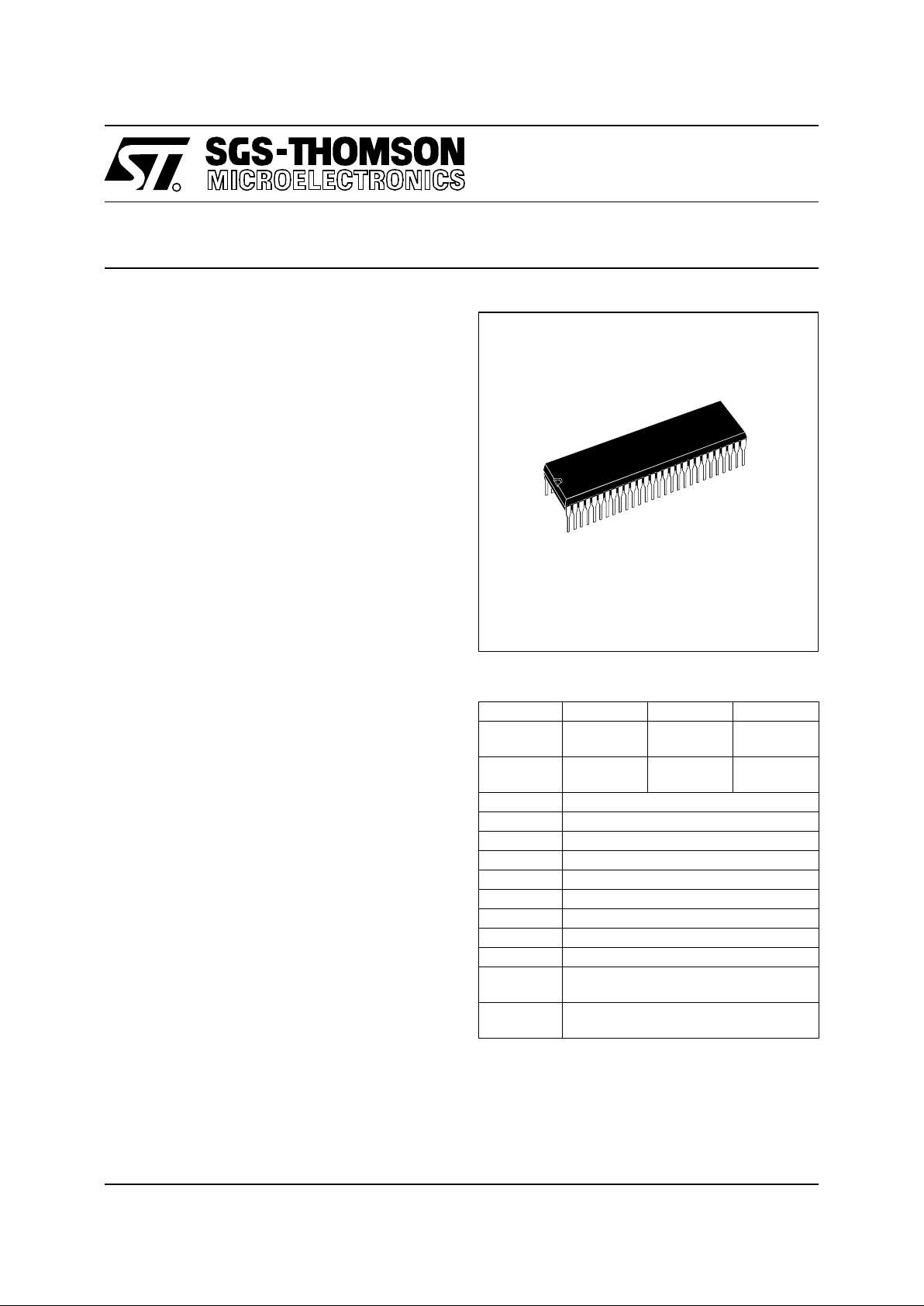
56-pin Shrink Dual In line Plastic package
■
Fully static operation
■
0 to + 70 oC operating temperature range
■
4.0V to 5.5V supply operating range
■
24 MHz Quartz Oscillator
■
63 basic instructions/17 main address modes
■
8x8 unsigned multiply instruction
■
True bit manipulation
■
Versatile Development Tools (DOS and
Windows) including assembler, linker, Ccompiler, archiver, source level debugger,
EPROM programme r and hardware emula tor
Device Summary
Note 1
: Power On/Off reset not implemented in
this revision.
Features ST72751N9 ST72751N7 ST72751N6
ROM
(bytes)
60K 48K 32K
RAM
(bytes)
2K 1.5 1
ADC 8 channels
Timer 1
I
2
C Bus one multimaster
DDC/DMA yes
Sync yes
PWM 9
I/O 32
SCI yes
IR yes
EPROM
Device
ST72E751N9D1
OTP
Device
ST72T751N9B1
PSDIP56
See Ordering Information at the end of the Document
1
Page 2
2/3
ST7275-1
1 GENERAL DESCRIPTION
1.1 INTRODUCTION
The ST7275 is a HCMOS microcontroller unit
(MCU) from the ST7 family with dedicated peripherals for Monitor applications.
It is based around an indu stry standard 8-bi t core
and offers an enhanced i nstruction set. The processor runs with an external clock at 24 MHz with
a 5V supply. Due to the fully static de sign of this
device, operation down to DC is possible. Under
software control the ST7275 can be placed in
WAIT or HALT mode thus reducing power consumption. The enhanced instruction set and addressing modes afford real programming potential.
In addition to standard 8-bit data management the
ST7 features true bit manipulation, 8x8 unsigned
multiplication and indirect addressing modes.
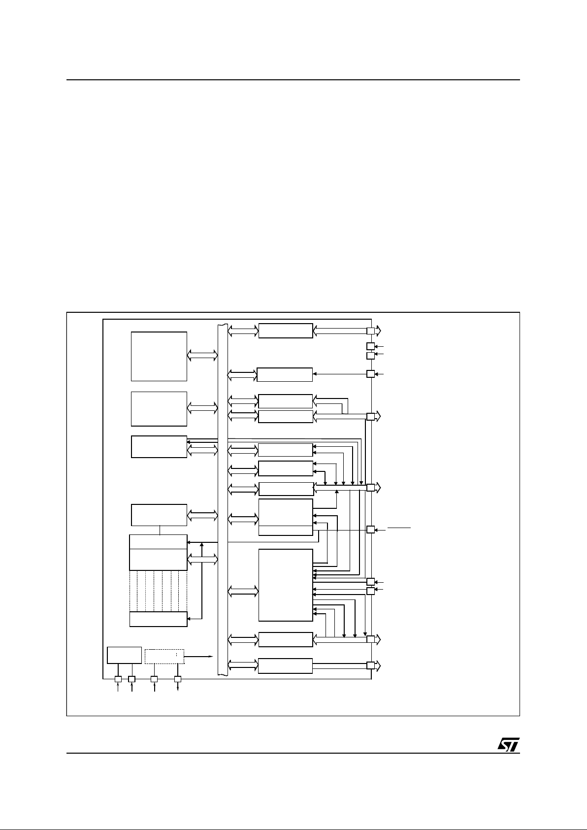
The device includes an on-chip oscillator, CPU,
Sync Processor for video timing & Vfbac k analysis, up to 60K ROM, up to 2K RAM, I/O, a timer
with 2 input captures and 2 output compares, an 8channel Analog to Digital Converter, DDC/DMA,
I
2
C multi Master, SCI Serial Comm unications Interface, Watchdog Reset, an Infra Red Control
preprocessor, and one 12-bit and eight 10-bit
PWM/BRM outputs for analog DC control of external functions.
Figure 1. ST7275-1 Block Diagram
SYNC
PROCES SO R
POWER
SUPPLY
OSC /3 or 6
V
DD
PORT A
PORT C
P
C
L
A
D
D
R
E
S
S
/
D
A
T
A
B
U
S
E
S
DDC
TIMER
WATCHDOG
PORT D
C
S
Y
N
C
I
H
S
Y
N
C
O
V
S
Y
N
C
O
H
/
C
S
Y
N
C
V
S
Y
N
C
OCMP
C
L
A
M
P
O
U
T
PWM/BRM
PORT B
ADC
AIN 0-AIN7
DA0
60K Bytes
RAM
2K Bytes
CONTROL
8-BIT CORE
ALU
P
C
H
S
P
X
Y
A
C
C
INTERNAL
CLOCK
V
SS
OSCOUTOSCIN
DA1,DA8
H
S
Y
N
C
I
2
V
S
Y
N
C
I
2
DDC DMA
H
F
B
A
C
K
PORT C
SCLD
SDAD
I²C
INF R A R E D
S
C
L
I
S
D
A
I
SCI
(UAR T)
VR017 35Q
PA0..6
PA7/BLANKOUT
V
DDA
V
SSA
PC3/SDAD
PC2/RX/SCLD
PC0/OCMP/HFBACK
RESET
HSYNCI1
VSYNCI1
PB1..7/ AIN1..7
VFBACK/AIN0
PC1/HSYNCI2
PC4/SCLI
PC5/SDAI
PC6/RDI
PC7/TDO
IRIN
POWER ON/OFF
TDO
RDI
ROM/
Up to
Up to
PB0/
PD0/CSYNCI
PD1/HSYNCO
PD2/VSYNCO
PD3/ITC
PD4/ITB
PD5/ITA
PD6/CLAMPOUT
PD7/VSYNCI2/ITD
OTP/EPROM
V
F
B
A
C
K
Page 3

Information furnish ed is believed to be accurate and relia ble. Howeve r, SGS-THOM SON Microel ectronics assu mes no
responsibility for the consequences of use of such information nor for any infringement of patents or other rights of third
parties which may result from its use. No license is granted by implication or otherwise under any patent or patent rights
of SGS-THOMSON Microelectroni cs. Specificati ons mentioned in this publication are sub ject to change witho ut notice.
This publication supersedes and replaces all information previously supplied. SGS-THOMSON Microelectronics products
are not authorized for use as critical components in life support devices or systems without the express written approval
of SGS-THOMSON Microelectronics.
1998 SG S-THOMSON Microelectronics - All Rights Reserved.
Purchas e of I
2
C Components by SGS-THOMSON Microelectronics conveys a license under t he Philips I2C Pate n t. Rig hts to use these
components in an I
2
C system is granted provided that the system conforms to the I2C Standard Specification as defined by Philips.
SGS-THOMSON Microelectronics GROUP OF COMPANIES
Australi a - Brazil - C anada - China - F rance - Ger m any - Italy - Japan - Korea - M alaysia - Ma l t a - Morocco - Th e Netherl ands - Singapore
Spain - Sweden - Switzerland - Tai wan - Thailand - United Kingdom - U.S. A.
 Loading...