

Page 1

查询ASCOT供应商
ST70134 - ST70135A
ASCOT ADSL MODEM CHIP SET FOR CPE
PRODUCT PREVIEW
■ COMPLETE CHIP SET FOR ADSL CPE
MODEM
■ COMPLIANCE WITH ANSI T1.413 ISSUE
1 & ISSUE 2
■ COMPLIANCE WITH G.992.1 (FULL RATE)
& G.992.2 (G. LITE)
■ IMPLEMENTS DISCRETE MULTITONE
(DMT) MODULATION AND DEMODULATION ON C P E S I DE
■ DATA RATES UP TO 8Mbps DOWNSTREAM
AND TO 1Mbps UPSTREAM WITH 32Kbps
GRANULARITY
■ BUILT-IN ATM TRANSPORT
■ SUPPORT ADAPTIVE RATE MODE IN
32Mbps INCREMENTS
■ 255/128 CARRIERS WITH 4.3125KHz
SPACING
■
DEDICATED SOFTWARE DRIVER A VAILABLE
■
PROCESSOR I NDE PENDEN T C++ S OURC E
COMPILATION
■ FREQUENCY DIVISION MULTIPLEXING
(FDM) FOR HIGH ROBUSTNESS IN PRESENCE OF CROSSTALK
■ REED-SOLOMON FORWARD ERROR
CORRECTION
■ TRELLIS CODER AND DECODER
■ PROGRAMMABLE SIMULTANEOUS SUP-
PORT OF INTERLEAVED AND NON-INTERLEAVED CHANNELS (DUAL LATENCY)
■ FULL, REDUCED AND MINIMAL ATM
OVERHEAD FRAMI N G MOD ES
■ BIT STREAM MODE CAPABLITY FOR STM
TRANSPORT
■ DIRECT CONNECTION TO ATM SYSTEMS
VIA UTOPIA IN TERFACE (LEVEL 1 OR 2)
■ MICROCONTROLLER INTERFACE WITH
16 BITS MULTIPLEXED ADDRESS/DATA
BUS
■ LOW POWER TECHNOLOGY: 1.3w TOTAL
■ SINGLE 3.3V POWER SUPPLY
■ 0 TO +70°C OPERATING TEMPERATURE
RANGE
APPLICATIONS
■ HIGH SPEED INTERNET ACCESS
■ REMOTE ACCESS TO CORPORATE NET-
WORK FOR TELECOMMUTERS AND
BRANCH OFFICES
■ VIDEO-ON-DEMAND OVER TWISTED PAIR
■ CPE ADSL MODEMS, AND ROUTERS
■ ADSL PC NIC's
■ G. LITE CPE SPLITTERLESS APPLICA-
TIONS
TQFP64 PQFP144
ORDERING NUMBERS:
ST70134 (TQFP64)
ST70135A (PQFP144)
This is advance information on a new product now in development or undergoing evaluation. Details are subject to change without noti ce.
1/8April 2000
Page 2

ST70134 - ST70135A
GENERAL DESCRIPTION
The ADSL modem chip set with ATM interface
provides all the active functions required to build a
complete ATM-based ADSL modem from line
interface to ATM UTOPIA bus. The chip set
employs Discrete MultiTone modulation as
specified in ANSI T1.413.
The chip set operates at CPE end of the loop
(ATU-R mode). Reed-Solomon forward error
correction plus Trellis coding with or without
interleaving in internal interleaving RAM p rovides
maximum noise immunity (see Figure 3).
Interleaving is optional and can be used
simultaneously on a slow channel (e.g., for data or
control info) while a fast channel (e.g., video)
operates without interleaving. ICs include rate
adaptation capabilities during show time.
In transmit direction the chip set allows to select
an attenuation of the signal in case of short loops
or large echo (politeness). In rec eive d irection t he
chip set can optionally control an external
multiplexer to select an external attenuation of the
signal in case o f short loops, and provide a 2-bit
output ex ternal gain control.
ASCOT chip set
ASCOT is a two-chip ADSL modem transcei ver.
STMicroelectronics provides the necessary
software for transceiver’s external controller.
ASCOT can easily be hooked up with ATM
systems through the built-in UTOPIA level 2/1
interface. That allows ATM traffic to be carried at
up to 8Mbit/s downstream and 1Mbit/s upstrea m,
over a very plain and widespread twisted pair.
ASCOT is intended for use at ATU-R end.
The modem control sof tware can be compiled as
C++ code, independently on the processor used.
The driver can be interfaced to any external real
time operating system.
These pages block diagrams show the main
functions built-in in ST70134 and ST70135A.
ASCOT chip set supports three different rate
adaptation modes: fixed rate adaptation mode,
fixed with capability to boost within fixed range,
dynamic rate adaptation during show time.
Modem’s performances are set by the following
parameters: Rate adapta tion mode, Downstream
and Upstream bit rate for both latency paths,
Noise margins (min, max and target typically at
10E-7 BER without RS, interleaving and trellis),
Maximum power spectral density for downstream,
Maximum power for both up and downstream,
Carrier mask (which tones are disabled),
maximum interleaving delay.
Tones from number 8 to number 255 can be used:
from 8 to 3 1 for upsteam s ignals and from 32 to
255 for downstream signals. Num bers 16 and 64
(96 for ADSL over ISDN) are dedicated to pilot
tones which are employed for synchronisation
purposes with ATU-C end. The software sets the
use of tones for optimisation of performances.
Time recovery is carried out by the chip-set
through the pilot tones. This activity is undertaken
in two steps in order to achieve no more than
2ppm with AT U-C.
The transceiver controller sof tware monitors line
and channel. As far as line is concerned noise
margin, attenuation, power, carrier load, relative
capacity occupation are checked.
Channel’s monitoring deals with cell-delineation,
actual ATM (fast and interleaved) up and
downstream rates.
Figure 1 : ADSL modem block configuration
UTOPIA
2/8
DMT MODEM ST70135A
µ CONTROL
MEMORY
AFE
ST70134
χ
UTP
χ
Page 3

ST70134 - ST70135A
ASCOT ICs
ASCOT consists of an Analog Front End
(ST70134) and a Discrete Multitone Modem
(ST70135A) integrated circuits which are
produced by STMicroelectronics.
Here below we will briefly go through the main
topics of both the ICs (see Figure 2 and Figure 3).
Analog Front End (ST70134)
HCMOS5A (0.5µm) mixed digital and analog
technology has been chosen to produce this
component that embodies the analog functions of
the ASCOT.
Automatic gain control amplifiers, placed at the
analog interface of transmit and receive paths,
allow to keep acceptable level of the signal ADC’s
and DAC’s resolution, that is 12-bit wide with
8.8MHz sampling rate.
A built-in driver allows for external clock
generation using a VCXO.
Figure 2 : Analog Front End block diagram
TRANSMIT-SI D E
ST70134 Analog Front End’s main features:
– Rx low noise amplifier (0-31dB in 1dB steps
– Tx pre-driver amplifier (-15dB -0)
– Two input ports allow selection of RX signals,
e.g. with or without external attenuation
– Program m able low pass and band pass filters
– 12 -bit DAC and ADC, sampling at 8.832MHz
– Xtal: 35.328MHz, ±50ppm, the accuracy of t he
frequency is determined by the External XTAL
– Direct connection to ST701 35A DMT modem
– Error correction on ADC output
– Anal og and digital loop back mo des
– Single 3.3V supply, or 3.3V analog and 3.0V
digital supplies
– Power dissipation 0.4W
– Power-down mode 0.1W
– TQFP64 (10 x 10mm body, 0.5mm pitch)
VCODAC XTAL DRIVER
4
MUX
RECEIVE- SIDE
4
MUX
12 Bits / 8.8MHz
DAC
12 Bits / 8.8MHz
DAC
G = -15...0dB
STEP 1dB
LPF
138KHz
G = 0...31dB
STEP 1dB
LNA
LPF
1.1MHz
3/8
Page 4
ST70134 - ST70135A
Discrete MultiTone Digital Modem (ST70135A)
The DMT modem has been developed in
HCMOS6 (0.35µm) technology. It performs PMD
(Physycal Medium Dep endant) sub-layer and TC
(Transmission Convergence) sub -layer functions.
In other words we can split the chip into two
separate blocks: the first one which carries out
modem functions (PMD sub layer) and a second
one in charge of ATM framing. The chip is
controlled and programmed by an external
processor and is seen as a memory mapped
device.
MODEM Functions
The modem part of the chip includes all the
necessary blocks needed for digitally DMT
mapping and demapping. A 14-bit code for every
carrier allows constellations with up to 16383
points. Internally, digital filters carry out Time
Equalization to reduce the effects of the inter
symbol interference. That is followed by Fast
Fourier Transform (in transmit direction an Inverse
FFT is performed) in order to change from time
domain to frequency domain. Afterwards a
Frequency Equalization cuts down carrier by
carrier the channel distortion, signal’s amplitude
attenuation and phase rotation. By efficient
algorithms, this block drives, through the
ST70134’s integrated VCXO controller, the NT
crystal oscillator wh ich comes up in an excel lent
synchronisation (less than 2ppm) with ATU-C.
FRAMING Functions
ST70135A performs framing functions for generic
and ATM TC sub layers.
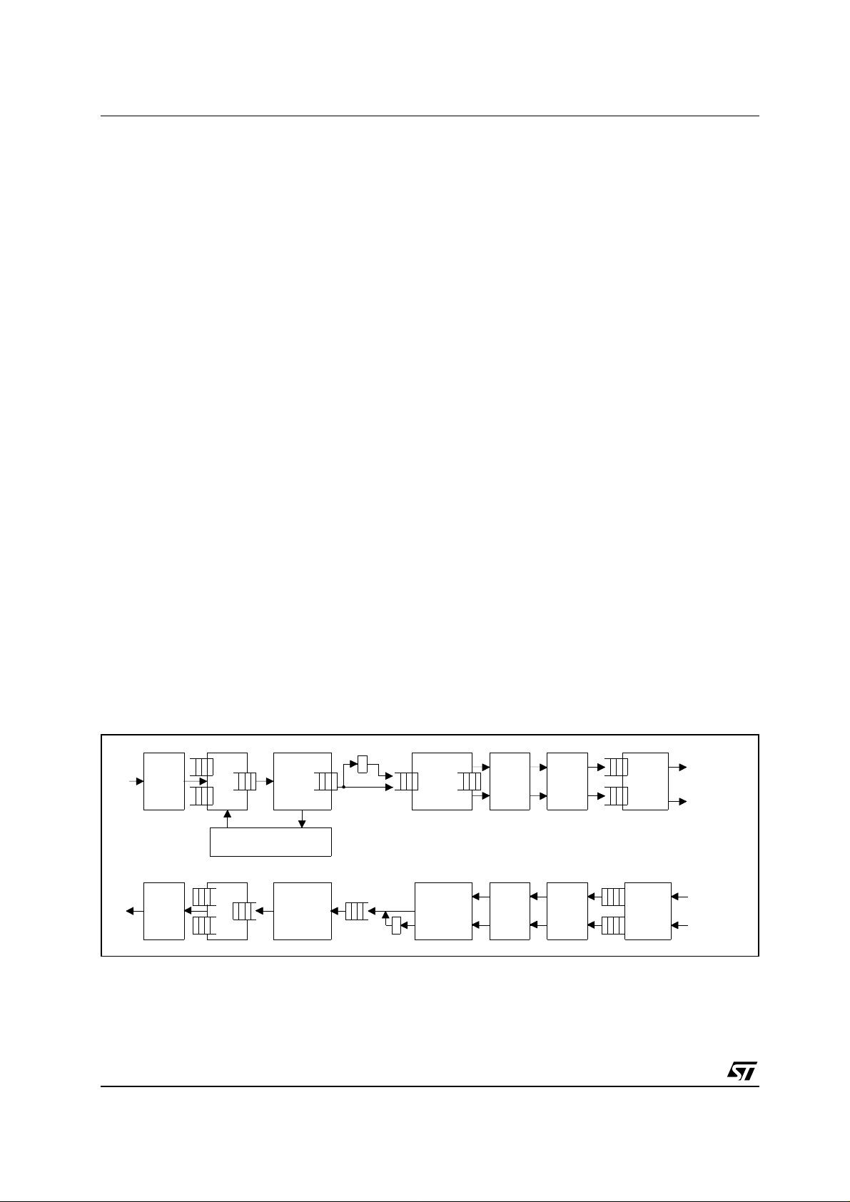
Figure 3 : DMT Modem block diagram
ATM TC sub layer performs cell level functions:
delineation, idle cells or unassigned cells
insertion/extraction, payload scrambling, Header
Error Correction (HEC) check and data frame
generation.
ST70135A DMT modem main features:
– Time-domain equalisation
– Ro tor and frequency-dom ain equal isation
– De cimation, interpolation
– FFT and IFFT
– Mappi ng/ dem apping over 256 carriers
– Trellis codin g and decoding u sing Viterbi algor ithm
– Error and noise monitoring on individual tones
– Reed-Solomon encoding and decoding
– (De) framing and (de) interleaving
– Ce ll HEC generation/verification
– Payload (de) scrambling
– AT M cell insertion/extraction
– Idle &/or Unassign ed cell insertion/filtering
– V P I/ V C I filt e r ing
– UTOP I A interface (Level 1 or 2)
– Microcontroller interface with 16-bit multipl exed
address/data bus and big/little endian format
supported
– JTAG test port
– Sing le 3.3V supply, 1.0W
– PQF P 144 (28 x 28mm body, 0.65mm pitch )
4/8
ADSL
AFE
Rx
DSP FE
Tx
DSP FE
FFT
SIGNAL MONITORING
& FEQ UPDATE & DPLL
IFFT
DEMAPPER
VITERBI
PMD SUBLAYER
MAPPER
VITERBI
R/S
DECODER
TC SUBLAYER ATM (UTOPIA)
R/S
CODER
DE-
FRAMER
FRAMER
CELL
BASED
FUNCT.
CELL
BASED
FUNCT.
Rx
INTERF.
Tx
INTERF.
INTERLEAVED
FAST
FAST
INTERLEAVED
Page 5
ST70134 - ST70135A
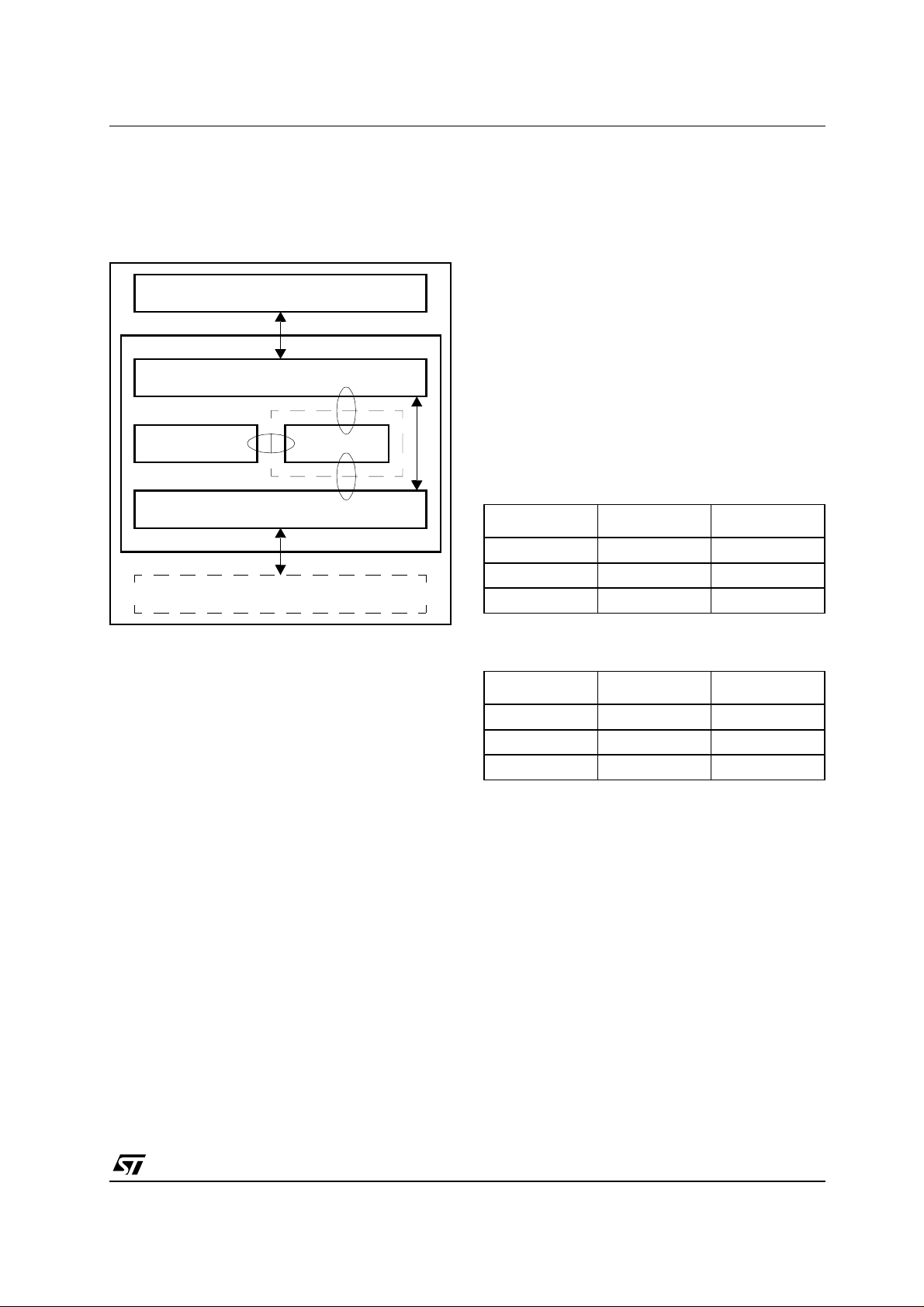
ADSL Modem control software
The ADSL transceiver is based on a
programmable DMT modem (ST70135A) whose
configuration is loaded by an external controller.
Figure 4 : Software Architecture
USER HIGH LEVEL SOFTWARE
ADSL MANAGEMENT APPLICATION SW
OS INTERFACE MODEM SW
BOARD SUPPORT PACK AGE
ADSL HARDWARE
The modem Software core comes with two
software modules: Board Support Package (BSP )
and Application Programming Interface (API).
BSP manages the hardw are dependent features
(i.e. interrupts, peripheral mapping).
APIs interface to the higher level application
software and to the OS.
ADSL Loop perf ormances
The hereafter tab les show the pe rformances that
a system, which houses ASCOT, can achieve for
ANSI and ETSI loops. The following result s refer
to an end-to end ADSL equipment with no
external disturbance.
ANSI Loop (26awg)
Length Downstream Upstream
9Kft 7.47 E +0.6 1.05 E +06
12Kft 3.69 E +0.6 9.37 E +05
15Kft 1.56 E +0.6 7.25 E +05
Additionally to the control functions, STMicroelectronics provides the DMT modem software.
The software is written in C++ language, and is
designed to be portable to any processor.
The driver has to be interfaced with a real time OS
kernel, it is compatible with any standard product
available on the m arket. The k ernel manag es the
tasks dedicated to modem soft wa re.
ETSI Loo p (Loop 2, noise model A)
Length Downstream Upstream
2Km 8.00 E +0.6 8.32 E +05
4Km 4.07 E +0.6 6.72 E +05
5Km 1.70 E +0.6 4.72 E +05
5/8
Page 6
ST70134 - ST70135A
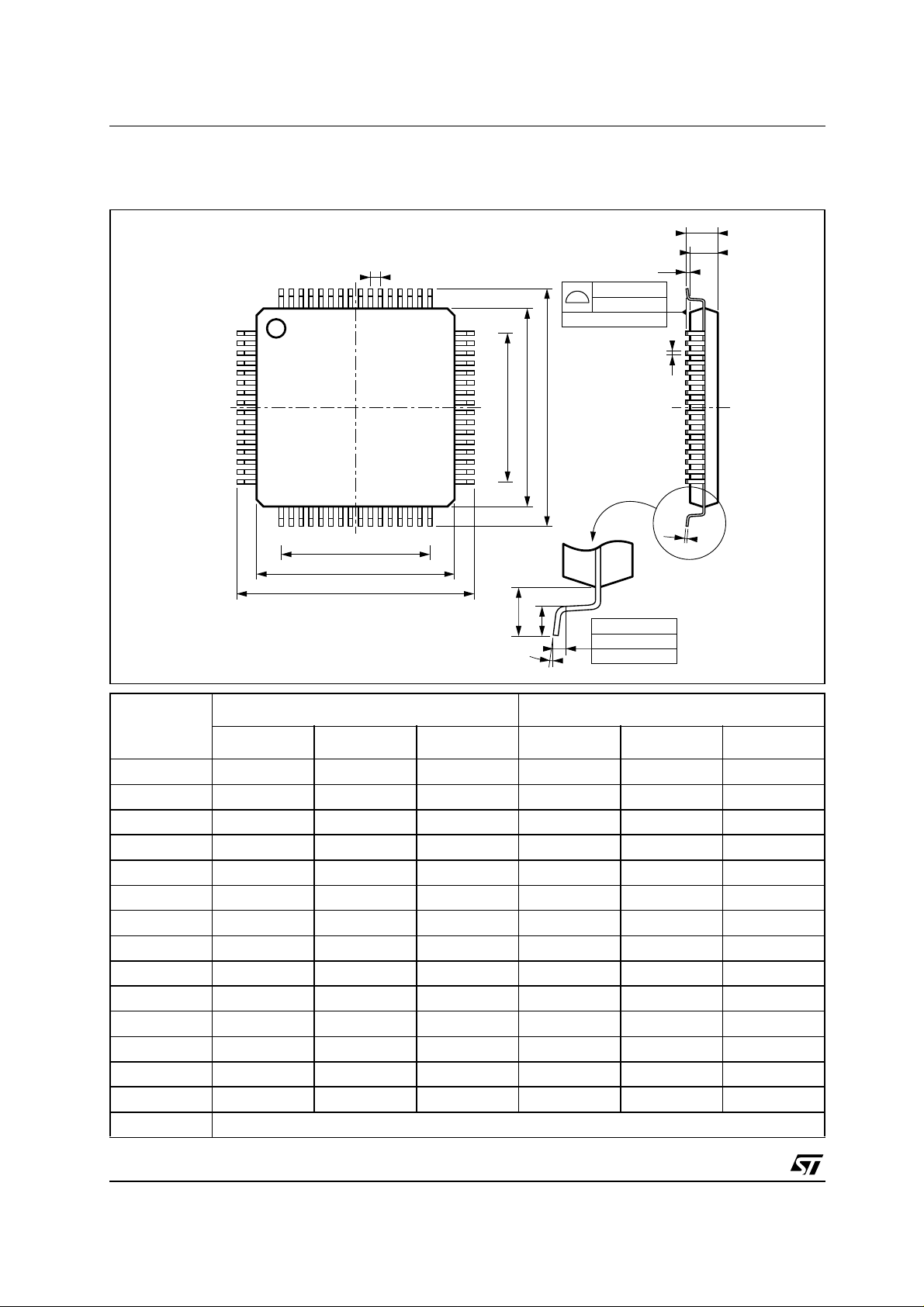
PACKAGE MECHANICAL DATA
Figure 5 : Package Outline TQFP64
A
A2
64 49
e
0,10 mm
.004 inch
SEATING PLANE
1
48
E3
E1
E
A1
B
16
17 32
D3
33
c
D1
D
L1
L
0,25 mm
.010 inch
K
Millimeter Inch
Dimension
Minimum Typical Maximum Minimum Typical Maximum
A 1.60 0.063
A1 0.05 0.15 0.002 0.006
A2 1.35 1.40 1.45 0.053 0.055 0.057
B 0.18 0.23 0.28 0.007 0.009 0.011
C 0.12 0.16 0.20 0.0047 0.0063 0.0079
D 12.00 0.472
D1 1 0.00 0.394
D3 7.50 0.295
e 0.50 0.0197
E 12.00 0.472
E1 10.00 0.394
E3 7.50 0.295
L 0 .40 0.60 0.75 0.0157 0.0236 0.0 295
L1 1.00 0.0393
K 0° (minimum), 7° (maximum)
GAGE PLANE
6/8
Page 7
ST70134 - ST70135A
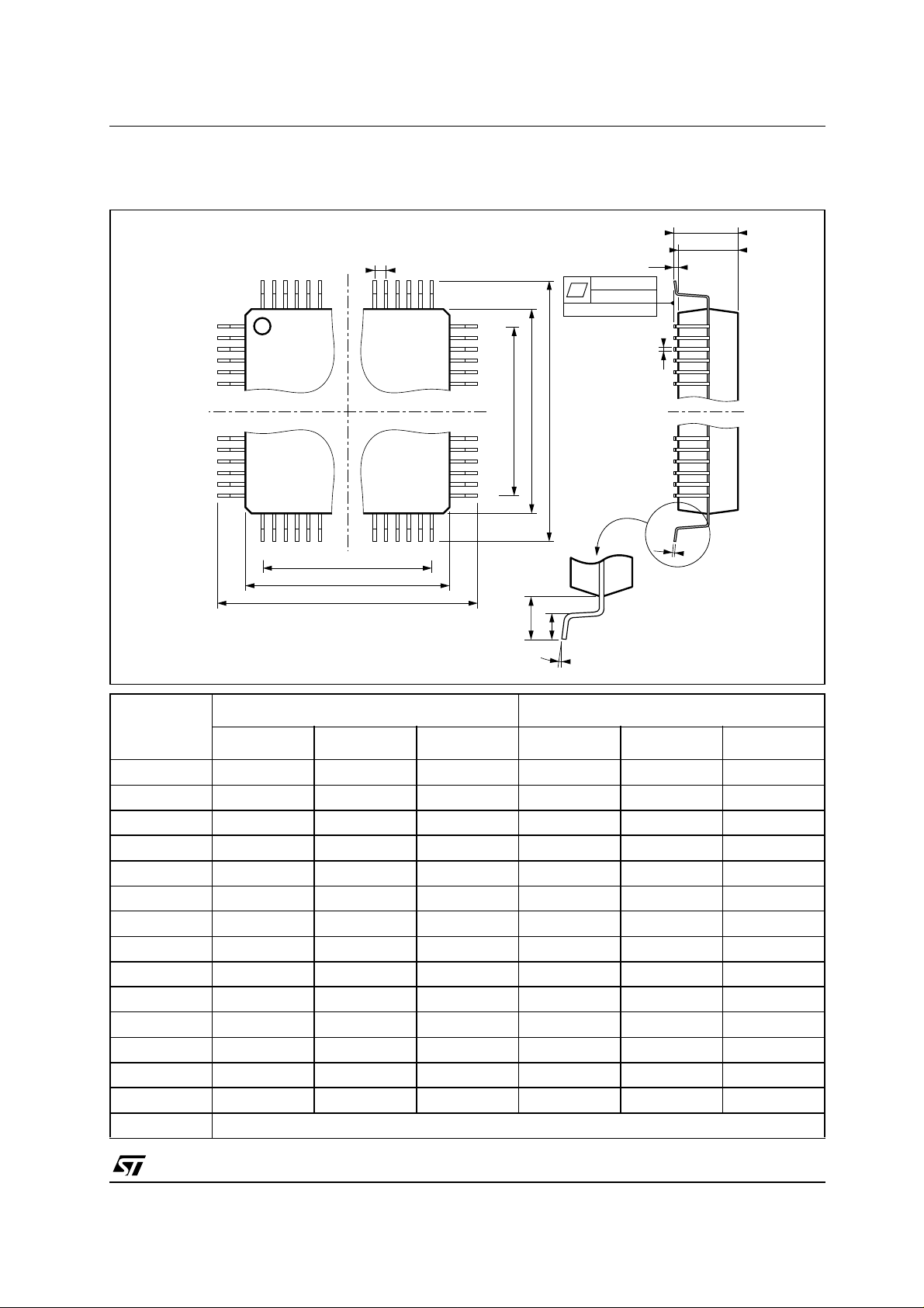
PACKAGE MECHANICAL DATA
Figure 6 : Package Outline PQFP144
A
A2
144 109
1
e
0,10 mm
.004 inch
SEATING PLANE
108
E
E3
E1
A1
B
36
37 72
D3
D1
D
73
L1
c
L
K
Millimeter Inch
Dimension
Minimum Typical Maximum Minimum Typical Maximum
A 4.07 0.160
A1 0.25 0.010
A2 3.17 3.42 3.67 0.125 0.135 0.144
B 0.22 0.38 0.009 0.015
C 0.13 0.23 0.005 0.009
D 30.95 31.20 31.45 1.219 1.228 1.238
D1 27 .90 28.00 28.10 1.098 1.102 1.106
D3 2 2.75 0.896
e 0.65 0.026
E 30.95 31.20 31.45 1.21 9 1.228 1.238
E1 27.90 28.00 28.10 1.09 8 1.102 1.106
E3 22.75 0.896
L 0 .65 0.80 0.95 0.026 0.031 0.037
L1 1.60 0.063
K 0° (minimum), 7° (maximum)
7/8
Page 8

ST70134 - ST70135A
Information furnished is bel ieved to be accurate and reliable. However, STMicroe lectronics assumes no responsibility for the
consequences of use of such information nor for any infringement of patents or other rights of third parties which may result from
its use. No li cense is granted by implication or otherwise under any patent or patent righ ts of S TMic roelec tronics. Specifications
mentioned in this publication ar e subject to change without notice. This publication supersedes and replaces all information
previously supplied. S TMicroelectronics products are not authorized for use as critica l components in life suppo rt devices or
systems without express written approval of STMicroelectronics.
The ST logo is a registered trademark of STMicroelectronics
© 2000 STMicroelectronics - All Rights Reserved
STMicroele ct ronics GROUP OF COMP A NI ES
Australi a - Brazil - China - Finland - France - Germany - Hong Kong - Indi a - Italy - Japan - Malaysia - Ma l ta - Morocco
Singapo re - Spain - Swe den - Switzerland - United K i ngdom - U.S.A.
http://www.st.com
8/8
 Loading...