

Page 1

查询ST20-JPI供应商
ST20-JPI
PC PARALLEL PORT TO JTAG INTERFACE
PRODUCT INFORMATION
FEATURES
• Desktop mounted parallel port to JTAG interface
• Standard 25 way D-type parallel port connection
• Standard 26 way D-type differential OS-Link
port for connection to a B300.
• Standard 20 way IDC cable for JTAG connection.
• Plug top power supply
• Supports nibble, byte and EPP mode parallel
port standards
DESCRIPTION
The ST20-JPI parallel port to JTAG interface is
a host interface to allow connection from a PC
parallel port to any JTAG diagnostic controller
based ST20 development board. The interface
plugs into any standard PC 25 way D-type
parallel port. Supported parallel port modes
are:
• Nibble mode
• Byte mode
• EPP mode
depending on which mode the host PC can
support. Connection to the development target
is via a 20 way IDC JTAG connector. Once
connected, the development target can be
accessed using the MS Windows drivers
supplied with the standard ST20 toolset.
September 1996
1/10
42 1685 00
Page 2

Contents
1 Introduction . . . . . . . . . . . . . . . . . . . . . . . . . . . . . . . . . . . . . . . . . . . . . . . . . . . . . . . . . . . . . 3
2 Installation . . . . . . . . . . . . . . . . . . . . . . . . . . . . . . . . . . . . . . . . . . . . . . . . . . . . . . . . . . . . . . 4
2.1 Hardware Installation - PC ..................................................................................................................... 4
2.2 Hardware Installation - B300 ................................................................................................................. 5
2.3 Software Installation .............................................................................................................................. 5
3 Connectors . . . . . . . . . . . . . . . . . . . . . . . . . . . . . . . . . . . . . . . . . . . . . . . . . . . . . . . . . . . . . 6
3.1 The ST20-JPI front panel ....................................................................................................................... 6
3.2 The ST20-JPI rear panel ....................................................................................................................... 6
3.3 Differential Link Connection ................................................................................................................... 7
3.4 JTAG Connection .................................................................................................................................. 7
3.5 TrigIn/TrigOut SMB Coaxial Connectors ............................................................................................... 8
3.6 Power Supply Connector ....................................................................................................................... 8
4 Recommended Target Circuitry . . . . . . . . . . . . . . . . . . . . . . . . . . . . . . . . . . . . . . . . . . . . 8
5 Field Support . . . . . . . . . . . . . . . . . . . . . . . . . . . . . . . . . . . . . . . . . . . . . . . . . . . . . . . . . . . . 9
6 Ordering information . . . . . . . . . . . . . . . . . . . . . . . . . . . . . . . . . . . . . . . . . . . . . . . . . . . . . 9
2/10
Page 3

ST20-JPI
1 Introduction
The ST20-JPI parallel port to JTAG interface is a host interface to allow connection from a PC
parallel port to any JTAG based ST20 development board. The interface plugs into any standard
PC 25 way D-type parallel port. Supported parallel port modes are:
• Nibble mode
• Byte mode
• EPP mode
depending on which mode the host PC can support. Connection to the development target is via a
JTAG connector.
drivers supplied with the standard ST20 toolset.
Once connected, the development target can be accessed using the MS Windows
3/10
Page 4
ST20-JPI
2 Installation
2.1 Hardware Installation - PC
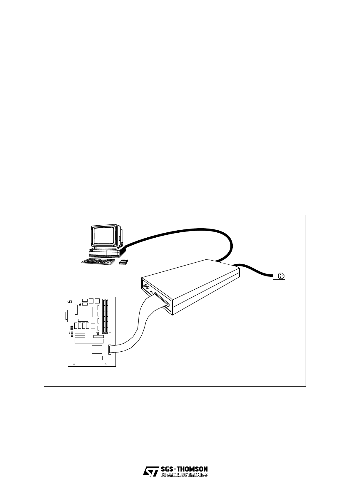
The ST20-JPI has six connections: Parallel port; Differential OS-Link, JTAG, TrigIn, TrigOut and
Power supply. To install the hardware connecting to a PC, the following steps should be followed:
• Plug the 25-way D-type of the par allel port cable built into the interf ace , into the par allel port
of the PC.
• Plug the target development system into the 20-way IDC connector using a 20 way IDC
cable.
• Plug power supply cable into PSU socket of the interface.
• Plug the power supply into the mains socket.
• Switch on the PC.
• Switch on the power supply. The LEDs on the interface should illuminate once the software
is running. For a description of the meaning of the LEDs, see the ST20 toolset documentation.
Host
Target development board
ST20
Figure 2.1 ST20-JPI connections basic configuration
Mains PSU
ST20-JPI
Parallel port to JTAG interface
4/10
Page 5

ST20-JPI
2.2 Hardware Installation - B300
The ST20-JPI can also be attached to the Ethernet via a B300. To install the hardware connecting
to a B300, the following steps should be followed:
• Connect the B300 to the ST20-JPI using a Differential OS-Link cable supplied with the
B300.
• Plug the target development system into the 20-way IDC connector using a 20 way IDC
cable.
• Plug power supply cable into PSU socket of the interface.
• Plug the power supply into the mains socket.
• Switch on the B300.
• Switch on the power supply to the ST20-JPI. The LEDs on the interface should illuminate
once the software is running. For a description of the meaning of the LEDs, see the ST20
toolset documentation.
• Switch on the Target power supply.
2.3 Software Installation
For installation of the DLL and VxD drivers, please refer to the ST20 Toolset software installation
documentation.
5/10
Page 6
ST20-JPI
3 Connectors
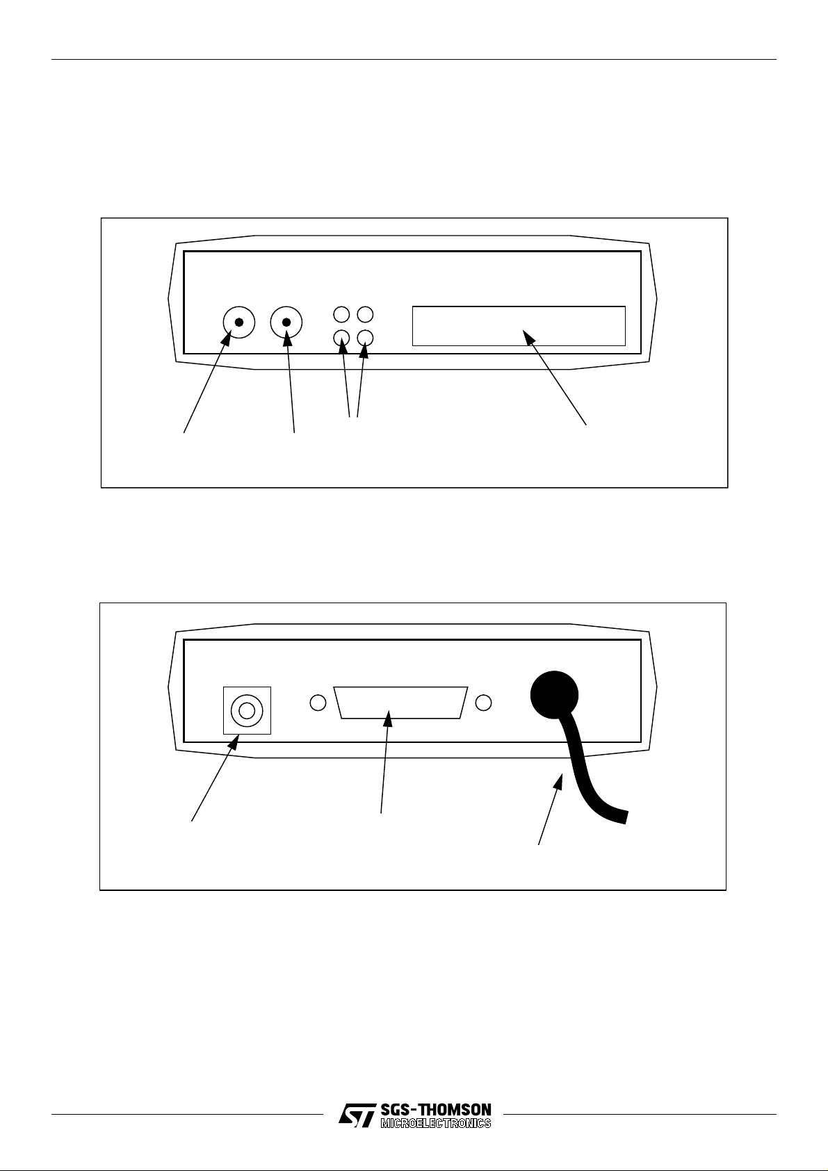
3.1 The ST20-JPI front panel
SMB
TrigOut
SMB
TrigIn
3.2 The ST20-JPI rear panel
PSU Connector
LEDs
Differential OS-Link
Parallel Port Connector
20 Pin IDC Header
JTAG Connection
6/10
Page 7

ST20-JPI
3.3 Differential Link Connection
The Differential OS-Link connector is used to connect the ST20-JPI to a B300 instead of a Parallel
port.
Pin Description Pin Description
1 +notSSDownReset 14 GND
2 +notSSDownAnalyse 15 GND
3 +notSSDownError 16 GND
4 +notSSUpReset 17 GND
5 +notSSUpAnalyse 18 GND
6 +notSSUpError 19 -notSSDownReset
7 +LinkOut 20 -notSSDownAnalyse
8 +LinkIn 21 -notSSDownError
9 GND 22 -notSSUpReset
10 GND 23 -notSSUpAnalyse
11 GND 24 -notSSUpError
12 GND 25 -LinkOut
13 GND 26 -LinkIn
Table 3.1 26 way D-type connector
3.4 JTAG Connection
The JTAG connector is a 20 pin male IDC header. The following table shows the pinout of the
ST20-JPI and the pinout required for the target board:
Pin Number Host Connection Target Connection
Even Numbers GROUND GROUND
1 Reserved Do Not Wire
3 TrigIn TrigOut
5 TrigOut TrigIn
7 Reserved Do Not Wire
9 TMS (Out) TMS (In)
11 TCK (Out) TCK (In)
13 TDO TDI
15 TDI TDO
17 notRST (Out) notRST (In)
19 notTRST (Out) notTRST (In)
Table 3.2 JTAG connector pinout
7/10
Page 8
ST20-JPI
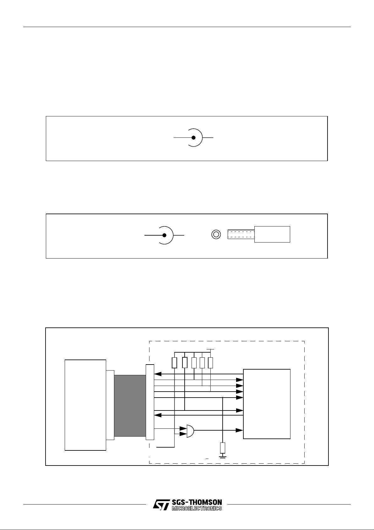
3.5 TrigIn/TrigOut SMB Coaxial Connectors
The two coaxial SMB connectors to the left of the LEDs are used to connect the ST20-JPI to a
Logic Analyser. They are used to signal between the Host, Target and Logical Analyser when an
event occurs. If, for instance, an event occurs on the Target processor, the TrigOut signal is
triggered which could start the Logic Analyser tracing an external event, so aiding software/
hardware debugging.
TrigIn/Out
GND
3.6 Power Supply Connector
The ST20-JPI uses a 2.5mm power connector. The voltage range is 8-13V dc.
GND+V
4 Recommended Target Circuitry
To ensure correct connection to the target processor, the following circuit should be used:
VCC
ST20-JPI
10K
Board PowerOnReset
ST20
TDO
TDI
TMS
TCK
notTRST
TrigIn
TrigOut
notRST
Target Board
8/10
Page 9
ST20-JPI
5 Field Support
SGS-THOMSON Microelectronics Limited products are supported worldwide through Sales
Offices and authorized distributors.
6 Ordering information
Description Order Number
ST20-JPI Parallel Port to JTAG Interface (US) ST20-JPI/110
ST20-JPI Parallel Port to JTAG Interface (European) ST20-JPI/220
ST20-JPI Parallel Port to JTAG Interface (UK) ST20-JPI/UK
Table 6.1 Ordering information
9/10
Page 10

ST20-JPI
10
Information furnished is believed to be accurate and reliable. However, SGS-THOMSON Microelectronics assumes no responsibility for the consequences of use of such information nor for any infringement of patents or other rights of third parties which may result from its use. No license is
granted by implication or otherwise under any patent or patent rights of SGS-THOMSON Microelectronics. Specifications mentioned in this publication
are subject to change without notice. This publication supersedes and replaces all information previously supplied. SGS-THOMSON Microelectronics
products are not authorized for use as critical components in life support devices or systems without express written approval of SGS-THOMSON
Microelectronics.
© 1996 SGS-THOMSON Microelectronics - All Rights Reserved
IMS and DS-Link are trademarks of SGS-THOMSON Microelectronics Limited.
is a registered trademark of the SGS-THOMSON Microelectronics Group.
Australia - Brazil - Canada - China - France - Germany - Hong Kong - Italy - Japan - Korea - Malaysia - Malta - Morocco -
The Netherlands - Singapore - Spain - Sweden - Switzerland - Taiwan - Thailand - United Kingdom - U.S.A.
SGS-THOMSON Microelectronics GROUP OF COMPANIES
10/10
 Loading...