

Datasheet ST2-L2-DC9V, ST2-L2-DC6V, ST2-L2-DC5V, ST2-L2-DC48V, ST2-L2-DC3V Datasheet (NAIS)
...Page 1
VDE
2 ×
3 ×
×
IC DRIVABLE PC BOARD
RELAY FOR FIELD LOAD
ST-RELAYS
SWITCHING
31
1.220
14
.551
11.3
.445
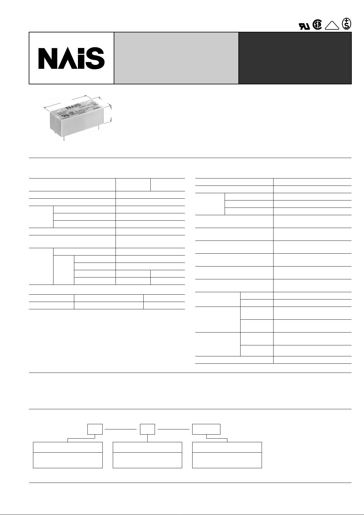
FEATURES
• Sealed to meet the combination process of automatic wave soldering
and cleaning needs
• Latching types available
mm inch
SPECIFICATIONS
Contacts
Arrangement
Contact material Gold flash over silver alloy
Initial contact resistance, max. 30 m Ω
Rating
(resistive)
Max. switching power 2,000 VA, 150 W
Max. switching voltage 380 V AC, 30 V DC
Max. switching current 8 A
HP rating 1/4 HP 125, 250 V AC
Inrush current capability
Mechanical (at 180 cpm) 10
Expected
life (min.
operations)
Electrical
8 A 250 V AC (resistive)
5 A 30 V DC (resistive)
3 A 100 V AC (lamp)
1 A 100 V AC (lamp)
Coil (polarized) (at 25 ° C 77 ° F)
Single side stable Nominal operating power Approx. 240 mW
Latching Nominal set and reset power Approx. 240 mW
Remarks
* Specifications will vary with foreign standards certification ratings.
1
Measurement at same location as "Initial breakdown voltage" section
*
2
*
Detection current: 10 mA
3
Wave is standard shock voltage of ± 1.2 × 50 µ s according to JEC-212-1981
*
4
*
Excluding contact bounce time
5
Half-wave pulse of sine wave: 11ms; detection time: 10 µ s
*
6
*
Half-wave pulse of sine wave: 6ms
7
*
Detection time: 10 µ s
8
Refer to 5. Conditions for operation, transport and storage mentioned in
*
AMBIENT ENVIRONMENT (Page 61).
1 Form A
1 Form B
2 Form A
51 A (TV-3 equivalence) for 1a1b
35 A (TV-1 equivalence) for 2a
7
5
10
5
10
4
10
—3
—
10
4
• High switching capacity and high
sensitivity in subminiature size
150 mW pick-up, 8 A inrush capacity:
51 A for 1a1b, 35 A for 2a
• High shock and vibration resistance
Shock: 20 G, Vibration: 10 to 55 Hz at
double amplitude of 2 mm
Characteristics (at 25 ° C 77 ° F 50% Relative humidity)
Max. operating speed
Initial insulation resistance*
Initial
breakdown
voltage*
Surge voltage between coil and
contact*
Operate time*
Between contact sets
Between open contacts
2
Between contacts and coil
3
4
1
(at nominal voltage)
Release time (without diode)*
4
(at nominal voltage)
Set time*
4
(latching)
(at nominal voltage)
Reset time*
4
(latching)
(at nominal voltage)
Temperature rise
(at 60 ° C)
Shock
resistance
Vibration
resistance
Conditions for operation,
transport and storage*
(Not freezing and condensing at low temperature)
Functional*
Destructive*
Functional*
Destructive
Ambient
8
temp.
Humidity 5 to 85% R.H.
5
6
7
Unit weight Approx. 10g .353 oz
20 cpm (at rated load)
1,000 M Ω (at 500 V DC)
2,000 Vrms
1,200 Vrms
3,750 Vrms
Min. 6,000 V
Max. 15 ms (Approx. 10 ms)
Max. 10 ms (Approx. 8 ms)
Max. 10 ms (Approx. 8 ms)
Max. 10 ms (Approx. 8 ms)
Max. 55 ° C with nominal coil voltage
and at 8 A switching current
Min. 196 m/s
Min. 980 m/s
117.6 m/s
2
{20 G}
2
{100 G}
2
{12 G}, 10 to 55 Hz
at double amplitude of 2 mm
176.4 m/s
2
{18 G}, 10 to 55 Hz
at double amplitude of 3 mm
–40 ° C to +60 ° C
–40 ° Fto +140 ° F
TYPICAL APPLICATIONS
Sequence controllers, facsimiles, telephone controls, remote
control security devices and security equipment.
ORDERING INFORMATION
Ex. ST
Contact arrangement
1: 1 Form A 1 Form B
2: 2 Form A
1 L2 DC48V
Operating function Coil voltage
Nil: Single side stable
L2: 2 coil latching
(Note) Standard packing: Carton; 50 pcs., Case; 500 pcs.
DC 3, 5, 6, 9, 12,
24, 48 V
249
Page 2
Ω ( ±
Ω ( ±
ST
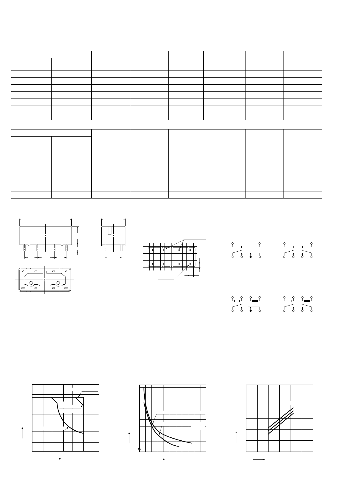
TYPES AND COIL DATA (at 20 ° C 68 ° F)
Single side stable
1 Form A
1 Form B
Part No.
2 Form A
Nominal
voltage,
V DC
Pick-up voltage,
V DC (max.)
Drop-out
voltage,
V DC (min.)
ST1-DC3V ST2-DC3V 3 2.4 0.3 4.5 38 75
ST1-DC5V ST2-DC5V 5 4.0 0.5 7.5 105 47
ST1-DC6V ST2-DC6V 6 4.8 0.6 9.0 150 40
ST1-DC9V ST2-DC9V 9 7.2 0.9 13.5 360 25
ST1-DC12V ST2-DC12V 12 9.6 1.2 18.0 600 20
ST1-DC24V ST2-DC24V 24 19.2 2.4 36.0 2,400 10
ST1-DC48V ST2-DC48V 48 38.4 4.8 72.0 9,000 4.7
2 coil latching
Part No.
1 Form A
1 Form B
2 Form A
ST1-L2-DC3V ST2-L2-DC3V 3 2.4 4.5 40 75
ST1-L2-DC5V ST2-L2-DC5V 5 4.0 7.5 110 47
ST1-L2-DC6V ST2-L2-DC6V 6 4.8 9.0 155 37.5
ST1-L2-DC9V ST2-L2-DC9V 9 7.2 13.5 360 25
ST1-L2-DC12V ST2-L2-DC12V 12 9.6 18.0 640 18.8
ST1-L2-DC24V ST2-L2-DC24V 24 19.2 36.0 2,400 9.8
ST1-L2-DC48V ST2-L2-DC48V 48 38.4 72.0 10,200 4.7
Nominal
voltage,
V DC
Set and reset
voltage,
V DC (max.)
Maximum allowable voltage,
V DC (60 ° C
DIMENSIONS
Maximum
allowable voltage,
V DC (60 ° C 140°F)
140°F
)
Coil resistance,
10%)
Coil resistance,
10%)
Nominal
operating
current, mA
Nominal
operating
current, mA
mm inch
31.0
1.220
11.0
.433
0.3
.012
3.5 .138
7.62
.300
85
10.16
.400
76
7.62
.300
4321
General tolerance: ± 0.2 ± .008
14
.551
10.16
.400
PC board pattern
(Copper-side view)
2 coil latching
types only.
8-DIA. 1.4
.055
Tolerance: ± 0.1 ± .004
2.54
.100
2.54
.100
Schematic (Bottom view)
Single side stable
1a1b 2a
14
–+
5678
(Deenergized condition)
2 coil latching
1a1b
12
–+
34
+–
5678
(Reset condition)
Diagram shows the "reset" position when terminals 3 and 4
are energized. Energize terminals 1 and 2 to transfer contacts.
REFERENCE DATA
1. Max. switching power 2. Life curve 3. Coil temperature rise
1,000
500
200
100
50
Life, 10 k operations
20
10
AC 250 V, 125 V resistive load
AC 250 V, 125 V inductive load
12345678910
Current, A
(Pf = 0.4)
10
5
2
1
Current, A
0.5
0.2
0.1
AC resistive load
AC
inductive load
(cosϕ =0.4)
DC resistive load
10 20 50 100 200 300
Voltage, V
Sample: ST1-DC24V
60
50
40
30
Temperature rise, °C
20
10
0
0.1 0.2 0.3 0.4 0.5
Coil operating power, W
14
–+
5678
2a
12–+34
Diagram shows the "reset" position when terminals 3 and 4
are energized. Energize terminals 1 and 2 to transfer contacts.
Contact current
8 A
5 A
0 A
+–
5678
250
Page 3
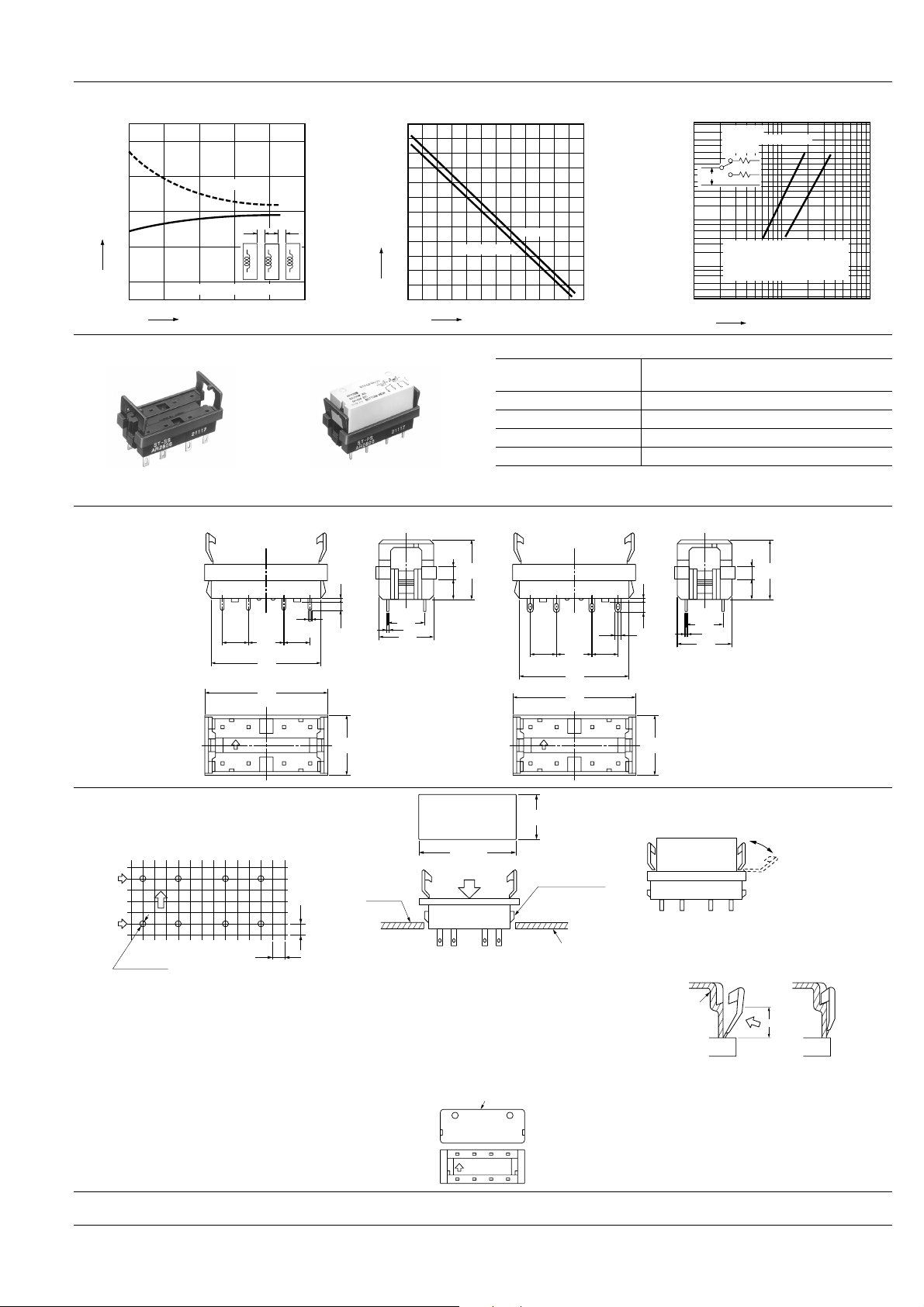
4. Influence of adjacent mounting
250 V AC
0.1 0.2 0.3 0.5 0.70.9
0.40.60.81.0
2.0 3.0 5.07.09.0
10 A
m = 3.9
η = 16.8×10
4
ρ
0.95
= 7.7×10
4
8 A
m = 3.5
η = 3.3×10
5
ρ
0.95
= 1.4×10
5
No. of operations, ×10
5
0.1
0.15
0.3
0.4
0.5
1.0
0.2
2.0
3.0
4.0
5.0
1.5
10.0
15.0
20.0
30.0
40.0
50.0
60.0
70.0
80.0
90.0
95.0
99.0
99.8
99.9
25.0
(%)
ST-Relay
250 V AC cos ϕ = 1.0
0.33 Hz
.
.
Relay case
cross-section
B
(Fastening complete)(Before fastening)
A
Sample: ST1-DC24V
20
10
0
Rated of change, %
–10
–20
Drop-out
Pick-up
(1) & (3) relays are energized.
5 101520
Inter-relay distance, mm
(1) (2) (3)
5. Max. ambient temperature by operating
power
120
110
100
90
80
70
60
50
Max. temperature, °C
40
30
20
10
0 0.20.40.6 0.8 1.0 1.2 1.4 1.6 1.82.02.2 2.4
8 A carrying
Operating power, mW
No load
6. Contact reliability
ST
ST relay socket
ST-SS
Solder terminal socket
DIMENSIONS
Specifications
Breakdown voltage
Insulation resistance More than 1,000 M Ω between terminals
Heat resistance 150 ° C (302 ° F) for 1 hr
Max. continuous current 10 A
Relay insertion life 15 times
ST-PS
PC board terminal socket
ST-PS ST-SS
4
.158
16.4
.646
0.3
7.62
.300
817
10.16
.400
31.6
1.244
35.4
1.394
2
1.05
.041
7.62
.300
635
.012
4.3
.169
16.6
.654
4
0.27
.011
10.16
.400
14.6
.575
5.5
.217
7.62
.300
8172635
10.16
.400
31.6
1.244
35.4
1.394
2.3
.090
7.62
.300
4,000 Vrms Coil/Contacts
2,000 Vrms Contacts/Contacts
mm inch
4
.158
16.4
5.5
.217
.646
0.3
.012
5.3
.209
16.6
.654
4
0.27
.011
10.16
.400
14.6
.575
Precautions for use (socket)
1. PC board mounting method
PC board pattern
Contact
terminal
interval
Coil
terminal
interval
The terminal configuration is symmetrical
on the left and right, so an arrow mark
is stamped on the socket to prevent misinsertion. We recommend printing the
same arrow mark
mounting side (side opposite from pattern) of the PC board. In this case, the terminal configuration becomes the terminal
nos. noted near the drilling holes.
87 65
12 34
8-1.5 DIA.
8-.060 DIA.
on the component
;
2.54
.100
2.54
.100
;
15.0±0.2
.591±.008
32.5±0.1
1.280±.004
Press
A side
Claw for chassis
fastening
Chassis t = 0.6 to 2.2
If the chassis hole is punched with a
press, set so the release R on the front
side (A side).
The range for chassis thickness is 0.6 to
2.2 mm .024 to .087 inch .
3. Relay mounting and removal
(1) Align the directions of the relay and socket.
Relay
.024 to .087
(2) Insert the relay all the way in, so it is securely in place.
Hinge
mechanism
(3) Press the part indicated by A in the B direction, and fasten by placing the hook on the relay.
(4). When removing the relay, completely release the hooks on both sides and pull the relay
out.
2. Chassis cutout
Chassis cutting dimensions
For Cautions for Use, see Relay Technical Information (Page 48 to 76).
9/1/2000 All Rights Reserved, © Copyright Matsushita Electric Works, Ltd.
251
Go To Online Catalog
 Loading...