

Page 1

6121 Baker Road,
Suite 108
Minnetonka, MN 55345
www.chtechnology.com
Phone (952) 933-6190
Fax (952) 933-6223
1-800-274-4284
Thank you for downloading this document from C&H Technology, Inc.
Please contact the C&H Technology team for the following questions -
Technical
Application
Assembly
Availability
Pricing
Phone – 1-800-274-4284
E-Mail – [email protected]
www.chtechnology.com - SPECIALISTS IN POWER ELECTRONIC COMPONENTS AND ASSEMBLIES - www.chtechnology.com
Page 2
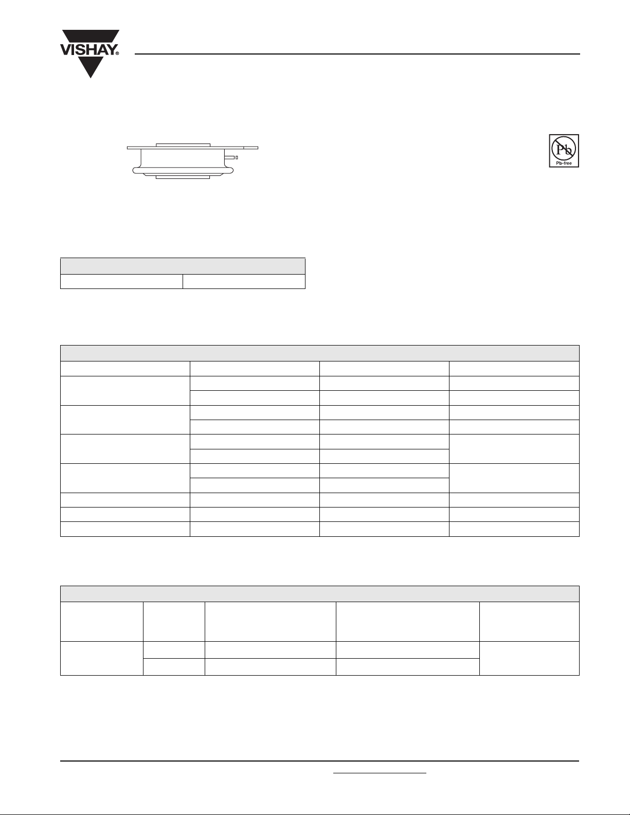
(Hockey PUK Version), 330 A
TO-200AB (A-PUK)
Vishay High Power Products
Inverter Grade Thyristors
FEATURES
• Metal case with ceramic insulator
• All diffused design
• Center amplifying gate
• Guaranteed high dV/dt
• International standard case TO-200AB (A-PUK)
• Guaranteed high dI/dt
• High surge current capability
• Low thermal impedance
• High speed performance
ST173CPBF Series
RoHS
COMPLIANT
PRODUCT SUMMARY
I
T(AV)
330 A
TYPICAL APPLICATIONS
•Inverters
• Choppers
• Induction heating
• All types of force-commutated converters
MAJOR RATINGS AND CHARACTERISTICS
PARAMETER TEST CONDITIONS VALUES UNITS
I
T(AV)
I
T(RMS)
I
TSM
2
I
t
V
DRM/VRRM
Range 15 to 30 µs
t
q
T
J
T
hs
T
hs
50 Hz 4680
60 Hz 4900
50 Hz 110
60 Hz 100
330 A
55 °C
610 A
25 °C
A
kA2s
1000 to 1200 V
- 40 to 125 °C
ELECTRICAL SPECIFICATIONS
VOLTAGE RATINGS
V
TYPE NUMBER
ST173C..C
VOLTAGE
CODE
10 1000 1100
12 1200 1300
DRM/VRRM
REPETITIVE PEAK VOLTAGE
, MAXIMUM
V
V
, MAXIMUM
NON-REPETITIVE PEAK VOLTAGE
RSM
V
I
DRM/IRRM
= TJ MAXIMUM
AT T
J
MAXIMUM
mA
40
www.vishay.com
Page 3
ST173CPBF Series
Vishay High Power Products
Inverter Grade Thyristors
(Hockey PUK Version), 330 A
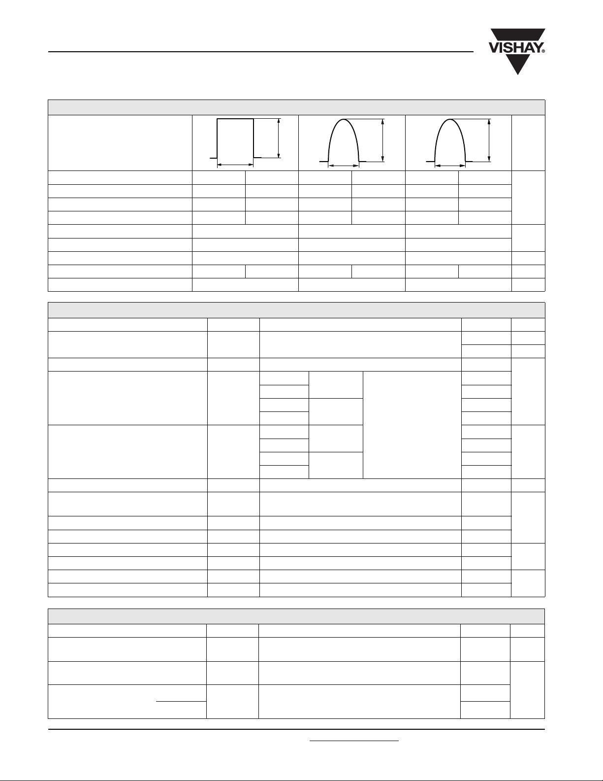
CURRENT CARRYING CAPABILITY
I
FREQUENCY UNITS
180° el
TM
180° el
50 Hz 760 660 1200 1030 5570 4920
400 Hz 730 590 1260 1080 2800 2460
1000 Hz 600 490 1200 1030 1620 1390
2500 Hz 350 270 850 720 800 680
Recovery voltage V
r
Voltage before turn-on V
d
50 50 50
V
DRM
Rise of on-state current dI/dt 50 - - A/µs
Heatsink temperature 40 55 40 55 40 55 °C
Equivalent values for RC circuit 47/0.22 47/0.22 47/0.22 Ω/µF
ON-STATE CONDUCTION
PARAMETER SYMBOL TEST CONDITIONS VALUES UNITS
Maximum average on-state current
at heatsink temperature
Maximum RMS on-state current I
I
T(RMS)
Maximum peak, one half cycle,
non-repetitive surge current
2
Maximum I
Maximum I
t for fusing I2t
2
√t for fusing I2√t t = 0.1 to 10 ms, no voltage reapplied 1100 kA2√s
Maximum peak on-state voltage V
Low level value of threshold voltage V
High level value of threshold voltage V
Low level value of forward slope resistance r
High level value of forward slope resistance r
Maximum holding current I
Typical latching current I
T(AV)
I
TSM
TM
T(TO)1
T(TO)2
t1
t2
H
L
180° conduction, half sine wave
double side (single side) cooled
DC at 25 °C heatsink temperature double side cooled 610
t = 10 ms
t = 8.3 ms 4900
t = 10 ms
t = 8.3 ms 4120
t = 10 ms
t = 8.3 ms 100
t = 10 ms
t = 8.3 ms 71
No voltage
reapplied
100 % V
reapplied
No voltage
reapplied
100 % V
reapplied
ITM = 600 A, TJ = TJ maximum,
= 10 ms sine wave pulse
t
p
(16.7 % x π x I
(I > π x I
T(AV)
(16.7 % x π x I
(I > π x I
T(AV)
< I < π x I
T(AV)
), TJ = TJ maximum 1.61
< I < π x I
T(AV)
), TJ = TJ maximum 0.77
TJ = 25 °C, IT > 30 A 600
TJ = 25 °C, VA = 12 V, Ra = 6 Ω, IG = 1 A 1000
I
TM
V
DRM
RRM
Sinusoidal half wave,
initial T
RRM
T(AV)
T(AV)
I
TM
100 µs
V
DRM
330 (120) A
55 (85) °C
4680
3940
= TJ maximum
J
110
77
2.07
), TJ = TJ maximum 1.55
), TJ = TJ maximum 0.87
kA
mΩ
mA
A
V
A
2
s
V
SWITCHING
PARAMETER SYMBOL TEST CONDITIONS VALUES UNITS
Maximum non-repetitive rate
of rise of turned on current
Typical delay time t
minimum
Maximum turn-off time
maximum 30
dI/dt T
d
t
q
= TJ maximum, V
J
TJ = 25 °C, VDM = Rated V
= Rated V
DRM
, ITM = 2 x dI/dt 1000 A/µs
DRM
, ITM = 50 A DC, tp = 1 µs
DRM
Resistive load, gate pulse: 10 V, 5 Ω source
TJ = TJ maximum,
I
= 300 A, commutating dI/dt = 20 A/µs
TM
V
= 50 V, tp = 500 µs, dV/dt: See table in device code
R
1.1
15
µs
Document Number: 94366
Page 4
ST173CPBF Series
Inverter Grade Thyristors
Vishay High Power Products
(Hockey PUK Version), 330 A
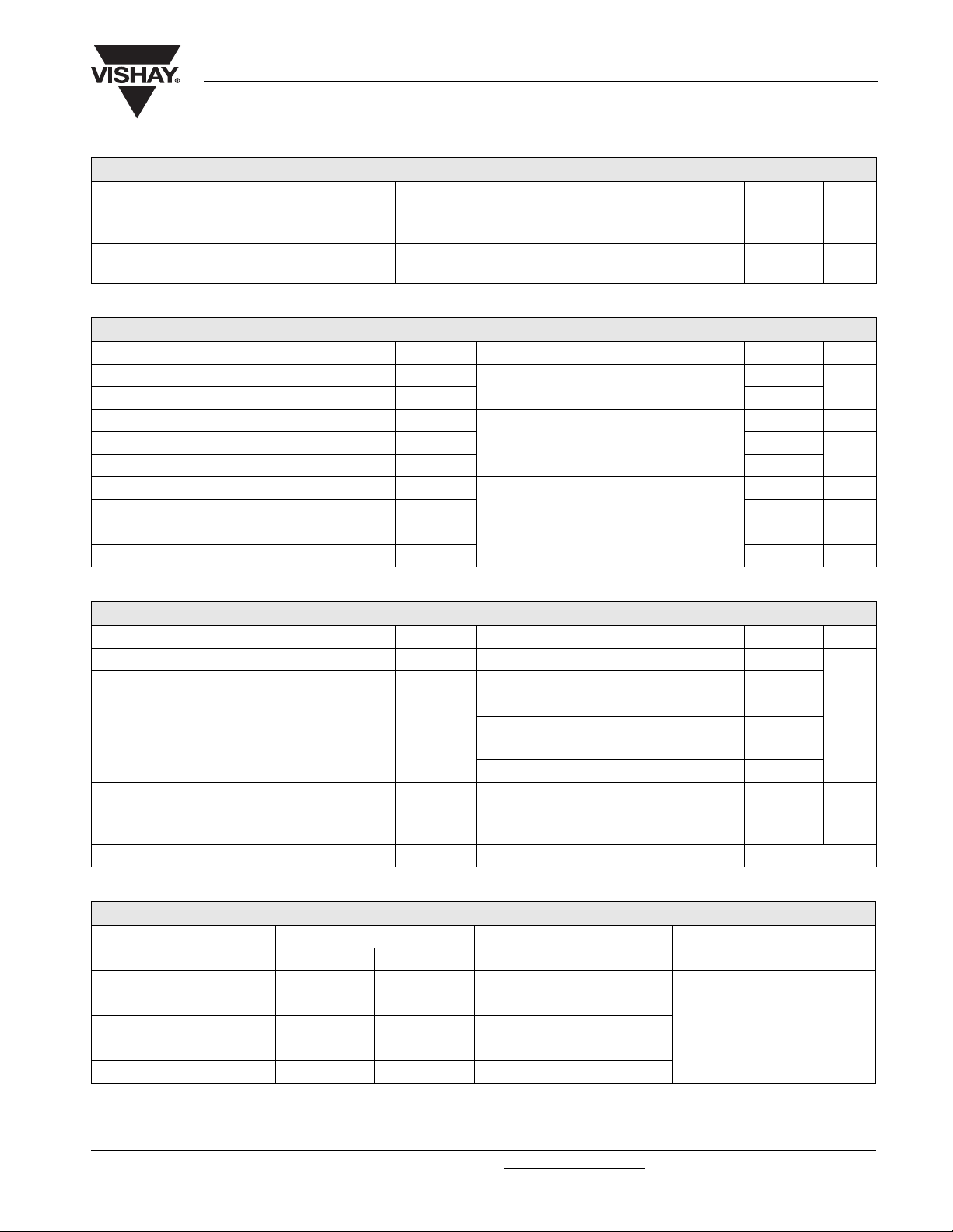
BLOCKING
PARAMETER SYMBOL TEST CONDITIONS VALUES UNITS
= TJ maximum, linear to 80 % V
T
Maximum critical rate of rise of off-state voltage dV/dt
I
Maximum peak reverse and off-state leakage current
RRM
I
DRM
,
J
higher value available on request
TJ = TJ maximum, rated V
DRM/VRRM
TRIGGERING
PARAMETER SYMBOL TEST CONDITIONS VALUES UNITS
Maximum peak gate power P
Maximum average gate power P
Maximum peak positive gate current I
Maximum peak positive gate voltage + V
Maximum peak negative gate voltage - V
Maximum DC gate current required to trigger I
Maximum DC gate voltage required to trigger V
Maximum DC gate current not to trigger I
Maximum DC gate voltage not to trigger V
GM
G(AV)
GM
GM
GM
GT
GT
GD
GD
TJ = TJ maximum, f = 50 Hz, d% = 50
TJ = TJ maximum, tp ≤ 5 ms
TJ = 25 °C, VA = 12 V, Ra = 6 Ω
TJ = TJ maximum, rated V
DRM
applied
,
DRM
500 V/µs
applied 40 mA
60
10
10 A
20
5
200 mA
3V
20 mA
0.25 V
W
V
THERMAL AND MECHANICAL SPECIFICATIONS
PARAMETER SYMBOL TEST CONDITIONS VALUES UNITS
Maximum operating junction temperature range T
Maximum storage temperature range T
Maximum thermal resistance, junction to heatsink R
Maximum thermal resistance, case to heatsink R
J
Stg
thJ-hs
thC-hs
DC operation single side cooled 0.17
DC operation double side cooled 0.08
DC operation single side cooled 0.033
DC operation double side cooled 0.017
Mounting force, ± 10 %
Approximate weight 50 g
Case style See dimensions - link at the end of datasheet TO-200AB (A-PUK)
ΔR
CONDUCTION
thJ-hs
CONDUCTION ANGLE
SINUSOIDAL CONDUCTION RECTANGULAR CONDUCTION
SINGLE SIDE DOUBLE SIDE SINGLE SIDE DOUBLE SIDE
TEST CONDITIONS UNITS
180° 0.015 0.016 0.011 0.011
120° 0.018 0.019 0.019 0.019
90° 0.024 0.024 0.026 0.026
T
60° 0.035 0.035 0.036 0.037
30° 0.060 0.060 0.060 0.061
Note
• The table above shows the increment of thermal resistance R
when devices operate at different conduction angles than DC
thJ-hs
- 40 to 125
- 40 to 150
4900
(500)
= TJ maximum K/W
J
°C
K/W
N
(kg)
Document Number: 94366 For technical questions, contact: [email protected]
www.vishay.com
Revision: 29-Apr-08 3
Page 5
ST173CPBF Series
Vishay High Power Products
130
120
110
100
90
80
70
Maximum Allowable
60
Heatsink Temperature (°C)
50
40
0
40
Average On-State Current (A)
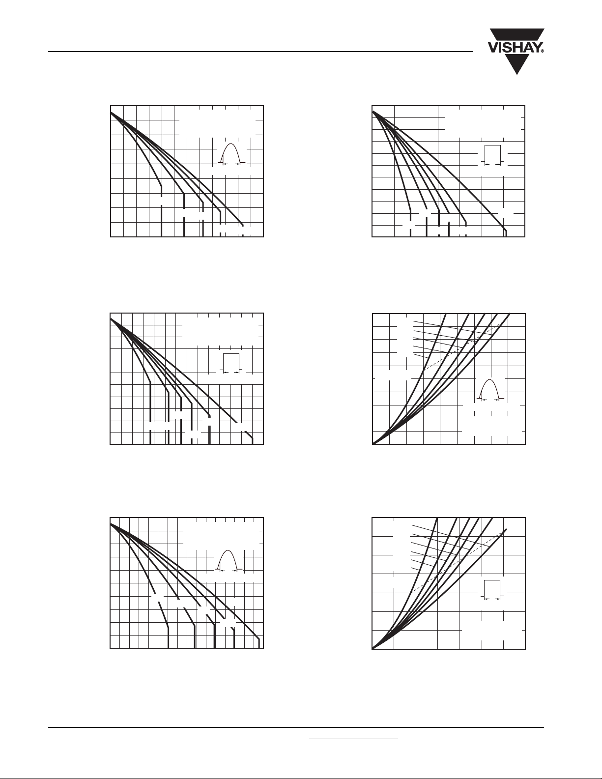
Fig. 1 - Current Ratings Characteristics
130
120
110
100
90
80
70
60
50
Maximum Allowable
40
Heatsink Temperature (°C)
30
20
0
30° 60°
100 200
50 150
Average On-state Current (A)
Fig. 2 - Current Ratings Characteristics
ST173C..C Series
(Single side cooled)
R
30°
60°
80
ST173C..C Series
(Single side cooled)
R
90°
120°
(DC) = 0.17 K/W
thJ-hs
Conduction angle
90°
(DC) = 0.17 K/W
thJ-hs
Conduction period
180°
250 300 350
Inverter Grade Thyristors
(Hockey PUK Version), 330 A
Ø
Maximum Allowable
Heatsink Temperature (°C)
120°
180°
200
240120 160
Ø
Power Loss (W)
DC
Maximum Average On-State
130
120
110
100
90
80
70
60
50
40
30
20
0
30°
200 400
100 300
ST173C..C Series
(Double side cooled)
R
60°
120°
90°
(DC) = 0.08 K/W
thJ-hs
Conduction period
180°
500 600 700
Average On-State Current (A)
Fig. 4 - Current Ratings Characteristics
1000
900
800
700
600
500
400
300
200
100
0
RMS limit
50 150
0
180°
120°
90°
60°
30°
100 200
Conduction angle
ST173C..C Series
T
= 125 °C
J
250 300 350 400 450
Average On-State Current (A)
Fig. 5 - On-State Power Loss Characteristics
Ø
DC
Ø
130
120
110
100
90
80
70
60
Maximum Allowable
50
Heatsink Temperature (°C)
40
30
0
30°
100 200
50 150
ST173C..C Series
(Double side cooled)
(DC) = 0.08 K/W
R
thJ-hs
Conduction angle
60°
90°
120°
250 300 350 400
Ø
180°
Average On-State Current (A)
Fig. 3 - Current Ratings Characteristics
1400
1200
1000
800
600
Power Loss (W)
400
200
Maximum Average On-State
DC
180°
120°
90°
60°
30°
RMS limit
Ø
Conduction period
ST173C..C Series
T
= 125 °C
J
0
100 200
0
300 400 500 600 700
Average On-State Current (A)
Fig. 6 - On-State Power Loss Characteristics
www.vishay.com For technical questions, contact: [email protected]
Document Number: 94366
4 Revision: 29-Apr-08
Page 6
ST173CPBF Series
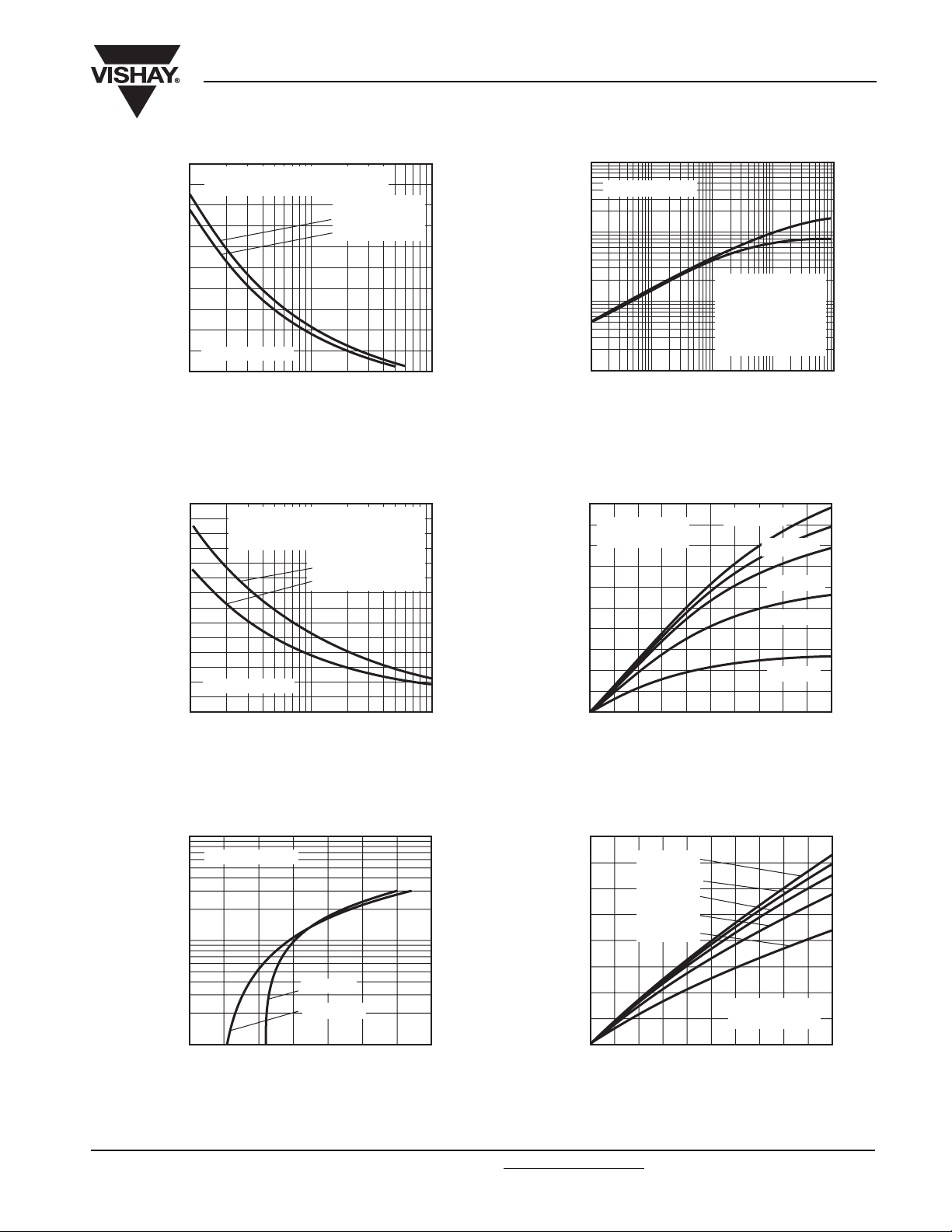
4500
4000
3500
3000
On-State Current (A)
Peak Half Sine Wave
2500
2000
At any rated load condition and with
rated V
ST173C..C Series
1 10 100
Number of Equal Amplitude Half Cycle
Fig. 7 - Maximum Non-Repetitive Surge Current
Single and Double Side Cooled
5000
4500
4000
3500
3000
2500
On-State Current (A)
Peak Half Sine Wave
2000
1500
0.01 0.1 1
Maximum non-repetitive surge current
versus pulse train duration. Control of
conduction may not be maintained.
ST173C..C Series
Fig. 8 - Maximum Non-Repetitive Surge Current
Single and Double Side Cooled
Inverter Grade Thyristors
(Hockey PUK Version), 330 A
applied following surge.
RRM
Current Pulses (N)
Pulse Train Duration (s)
Initial TJ = 125 °C
at 60 Hz 0.0083 s
at 50 Hz 0.0100 s
Initial TJ = 125 °C
No voltage reapplied
Rated V
RRM
reapplied
Vishay High Power Products
1
ST173C..C Series
(K/W)
0.1
thJ-hs
Steady state value
= 0.17 K/W
R
0.01
Transient Thermal
Impedance Z
0.001
0.01 0.1 1 100.001
Square Wave Pulse Duration (s)
Fig. 10 - Thermal Impedance Z
250
ST173C..C Series
= 125 °C
T
J
200
150
100
- Maximum Reverse
rr
50
Recovery Charge (µC)
Q
0
200 40 60 80 100
dI/dt - Rate of Fall of On-State Current (A/µs)
Fig. 11 - Reverse Recovered Charge Characteristics
thJ-hs
(Single side cooled)
= 0.08 K/W
R
thJ-hs
(Double side cooled)
(DC operation)
thJ-hs
ITM = 500 A
Characteristics
ITM = 300 A
ITM = 200 A
ITM = 100 A
ITM = 50 A
10 000
ST173C..C Series
1000
TJ = 25 °C
TJ = 125 °C
Instantaneous On-State Current (A)
100
1.0 1.5 2.0 2.5 3.0 3.5 4.0 4.5
Instantaneous On-State Voltage (V)
Fig. 9 - On-State Voltage Drop Characteristics
160
140
120
100
80
60
40
- Maximum Reverse
rr
Recovery Current (A)
I
20
0
ITM = 500 A
= 300 A
I
TM
= 200 A
I
TM
= 100 A
I
TM
= 50 A
I
TM
ST173C..C Series
= 125 °C
T
J
200 40 60 80 100
dI/dt - Rate of Fall of Forward Current (A/µs)
Fig. 12 - Reverse Recovered Current Characteristics
Document Number: 94366 For technical questions, contact: [email protected]
www.vishay.com
Revision: 29-Apr-08 5
Page 7
ST173CPBF Series
Vishay High Power Products
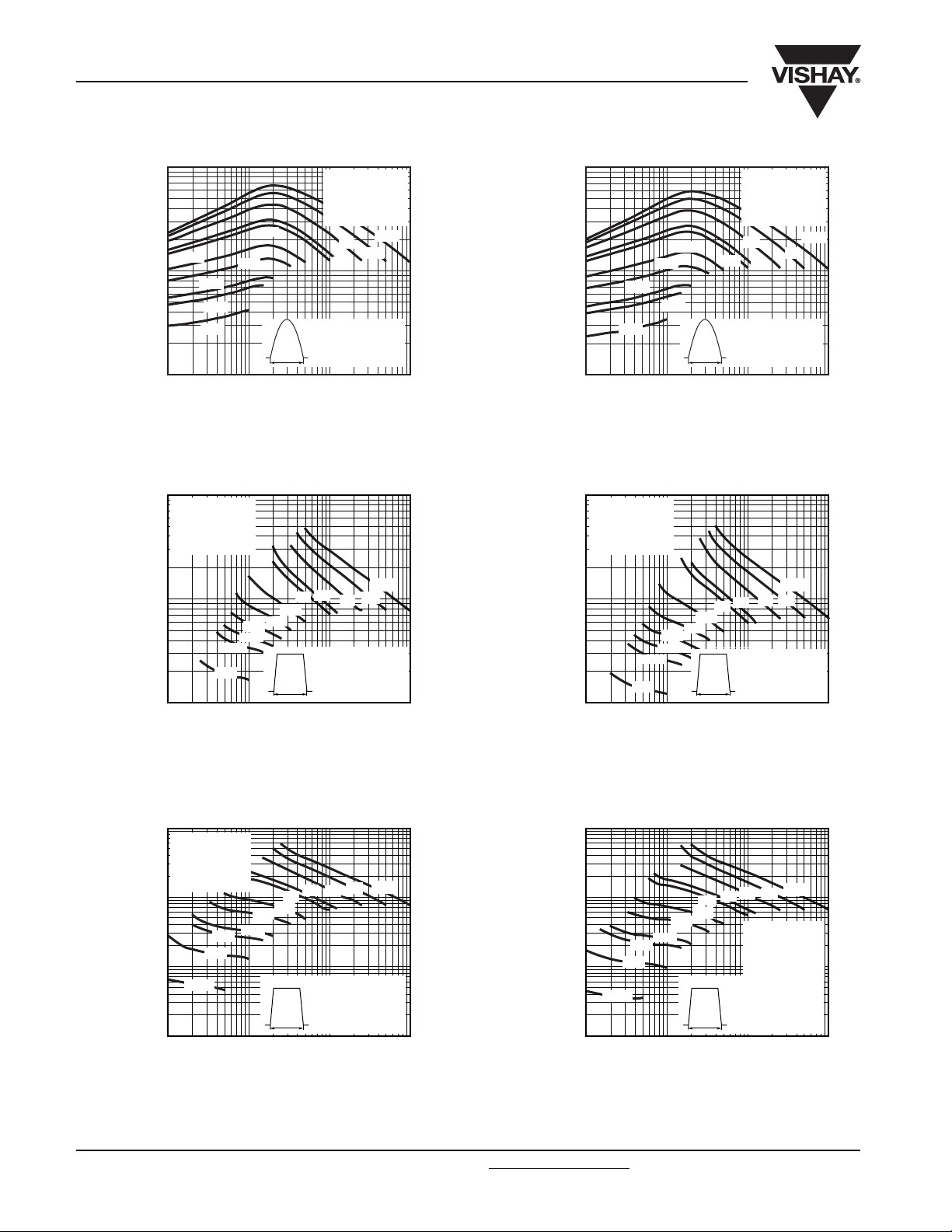
10 000
1000
1000
1500
2500
3000
5000
Peak On-State Current (A)
100
10 100 1000 10 000
Pulse Basewidth (µs)
10 000
Snubber circuit
= 47 Ω
R
s
= 0.22 µF
C
s
= 80 % V
V
D
DRM
500
ST173C..C Series
Sinusoidal pulse
t
p
= 40 °C
T
C
Snubber circuit
R
s
C
s
V
D
200
400
Inverter Grade Thyristors
(Hockey PUK Version), 330 A
10 000
= 47 Ω
= 0.22 µF
= 80 % V
DRM
50 Hz
100
1000
Peak On-State Current (A)
Fig. 13 - Frequency Characteristics
10 000
Snubber circuit
= 47 Ω
R
s
= 0.22 µF
C
s
= 80 % V
V
D
1000
1500
2500
3000
5000
100
10 100 1000 10 000
200
500
ST173C..C Series
Sinusoidal pulse
t
p
= 55 °C
T
C
400
100
Pulse Basewidth (µs)
Snubber circuit
= 47 Ω
R
s
= 0.22 µF
C
s
= 80 % V
V
D
DRM
DRM
50 Hz
1000
2000
2500
3000
Peak On-State Current (A)
5000
100
10 100 1000 10 000
Pulse Basewidth (µs)
10 000
Snubber circuit
= 47 Ω
R
s
= 0.22 µF
C
s
= 80 % V
V
D
DRM
1000
1500
2500
3000
5000
100
10 000
Peak On-State Current (A)
10
10 100 1000 10 000
Pulse Basewidth (µs)
1500
1000
1000
t
t
500
p
500
p
400
200
50 Hz
100
400
ST173C..C Series
Trapezoidal pulse
= 40 °C
T
C
dI/dt = 50 A/µs
50 Hz
100
200
ST173C..C Series
Trapezoidal pulse
= 40 °C
T
C
dI/dt = 100 A/µs
1000
Peak On-State Current (A)
100
Fig. 14 - Frequency Characteristics
10 000
1000
100
Peak On-State Current (A)
10
Fig. 15 - Frequency Characteristics
50 Hz
200
100
400
500
1000
1500
2000
5000
3000
2500
ST173C..C Series
Trapezoidal pulse
= 55 °C
T
C
t
p
dI/dt = 50 A/µs
10 100 1000 10 000
Pulse Basewidth (µs)
50 Hz
200
100
400
500
1000
10 000
3000
5000
1500
2500
ST173C..C Series
Trapezoidal pulse
T
C
t
p
dI/dt = 100 A/µs
Snubber circuit
= 47 Ω
R
s
= 0.22 µF
C
s
= 80 % V
V
D
= 55 °C
DRM
10 100 1000 10 000
Pulse Basewidth (µs)
www.vishay.com For technical questions, contact: [email protected]
Document Number: 94366
6 Revision: 29-Apr-08
Page 8
ST173CPBF Series
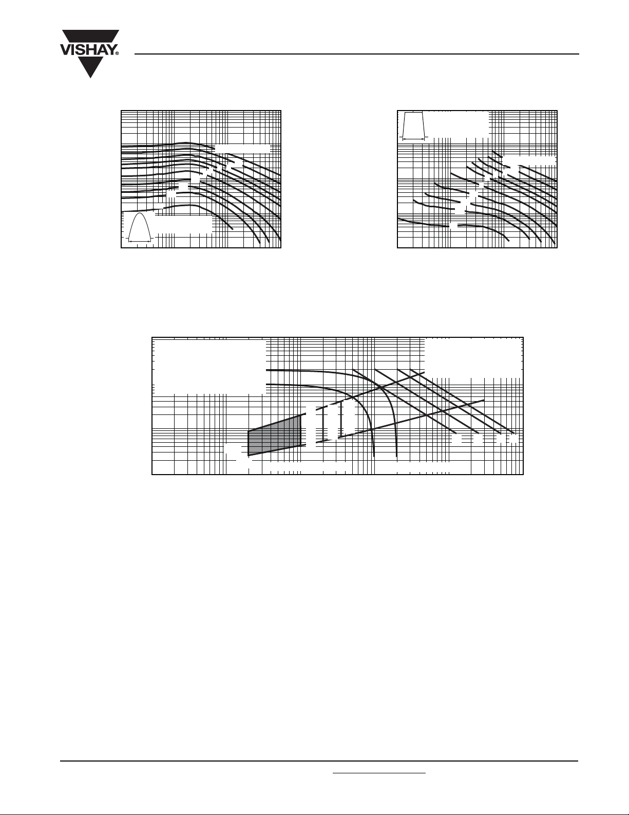
100 000
10 000
1000
100
Peak On-State Current (A)
t
p
10
10 100 1000 10 000
0.3
0.2
0.1
ST173C..C Series
Sinusoidal pulse
Pulse Basewidth (µs)
100
Rectangular gate pulse
a) Recommended load line for
rated dI/dt: 20 V, 10 Ω; t
b) Recommended load line for
≤ 30 % rated dI/dt: 10 V, 10 Ω
10
≤ 1 µs
t
r
1
Instantaneous Gate Voltage (V)
0.1
0.001
Inverter Grade Thyristors
Vishay High Power Products
(Hockey PUK Version), 330 A
100 000
10 000
1000
0.5
1
20 joules per pulse
10
5
3
2
100
Peak On-State Current (A)
10
10 100 1000 10 000
Fig. 16 - Maximum On-State Energy Power Loss Characteristics
≤ 1 µs
r
(a)
(b)
T
J
T
J
= 25 °C
= 40 °C
Frequency limited by P
T
J
= 125 °C
V
GD
I
GD
Device: ST173C..C Series
0.01 0.1 1 10 100
Instantaneous Gate Current (A)
Fig. 17 - Gate Characteristics
ST173C..C Series
Rectangular pulse
t
dI/dt = 50 A/µs
p
0.3
0.2
0.1
Pulse Basewidth (µs)
(1) PGM = 10 W, tp = 20 ms
= 20 W, tp = 10 ms
(2) P
GM
(3) P
= 40 W, tp = 5 ms
GM
(4) P
= 60 W, tp = 3.3 ms
GM
(1) (2)
G(AV)
0.5
3
2
1
(3)
20 joules per pulse
10
5
(4)
Document Number: 94366 For technical questions, contact: [email protected]
www.vishay.com
Revision: 29-Apr-08 7
Page 9
ST173CPBF Series
Vishay High Power Products
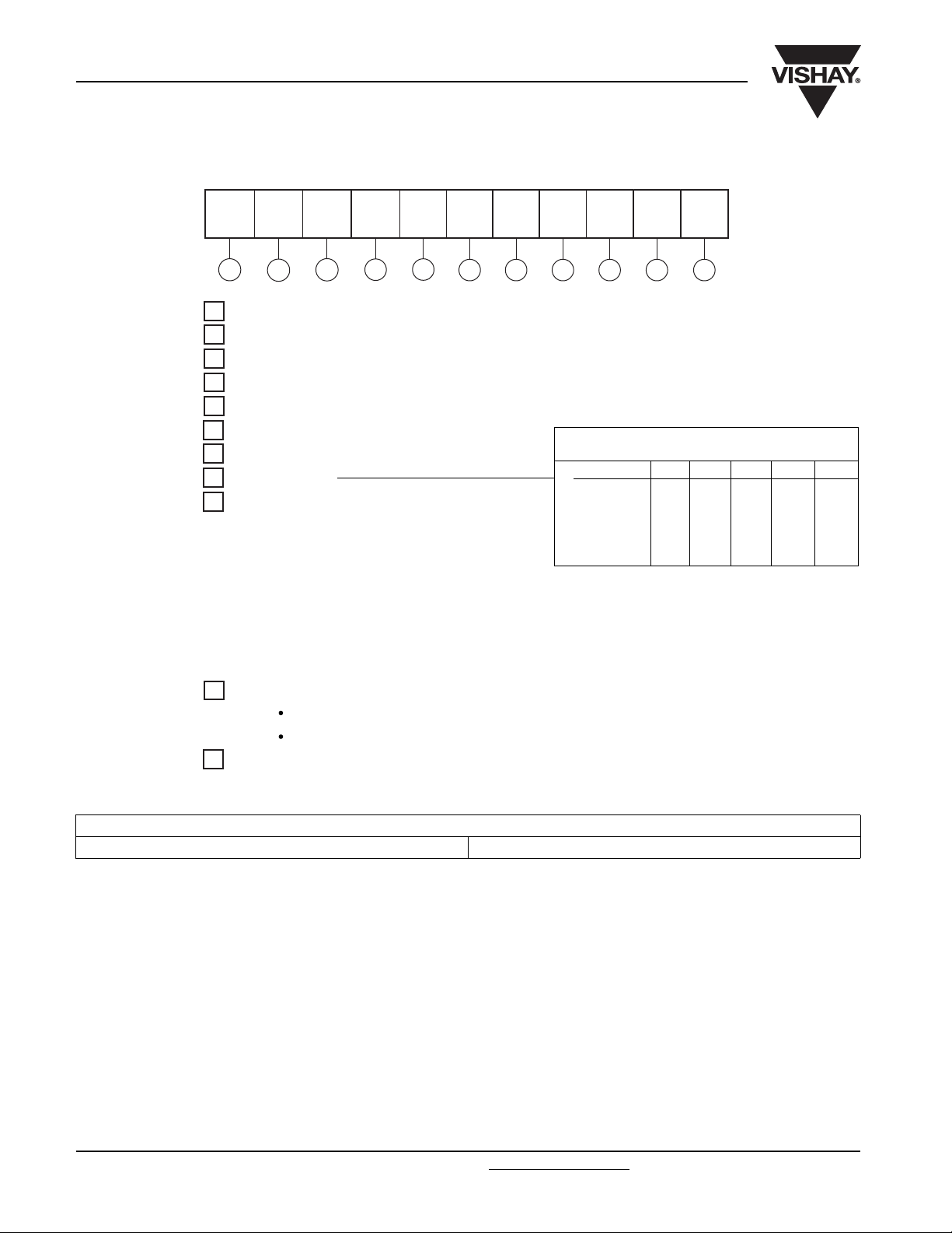
ORDERING INFORMATION TABLE
Device code
ST 17 3 C 12 C H K 1 - P
324
1 - Thyristor
2 - Essential part number
3 - 3 = Fast turn-off
4 - C = Ceramic PUK
5 - Voltage code x 100 = V
6 - C = PUK case TO-200AB (A-PUK)
7 - Reapplied dV/dt code (for t
8 -t
9 - 0 = Eyelet terminals
code
q
(gate and aux. cathode unsoldered leads)
1 = Fast-on terminals
(gate and aux. cathode unsoldered leads)
2 = Eyelet terminals
(gate and aux. cathode soldered leads)
3 = Fast-on terminals
(gate and aux. cathode soldered leads)
Inverter Grade Thyristors
(Hockey PUK Version), 330 A
51
6 7 8 9 10 11
(see Voltage Ratings table)
RRM
test condition)
q
dV/dt (V/µs) 20 50 100 200 400
tq(µs)
* Standard part number.
All other types available only on request.
dV/dt - tq combinations available
15 CL -- -- -- -18 CP DP EP FP * -20 CK DK EK FK * HK
25 CJ DJ EJ FJ HJ
30 -- DH EH FH HH
- Critical dV/dt:
10
None = 500 V/µs (standard value)
L = 1000 V/µs (special selection)
11
- P = Lead (Pb)-free
LINKS TO RELATED DOCUMENTS
Dimensions http://www.vishay.com/doc?95074
Document Number: 94366
 Loading...