

Page 1
查询Q62702-P1631供应商
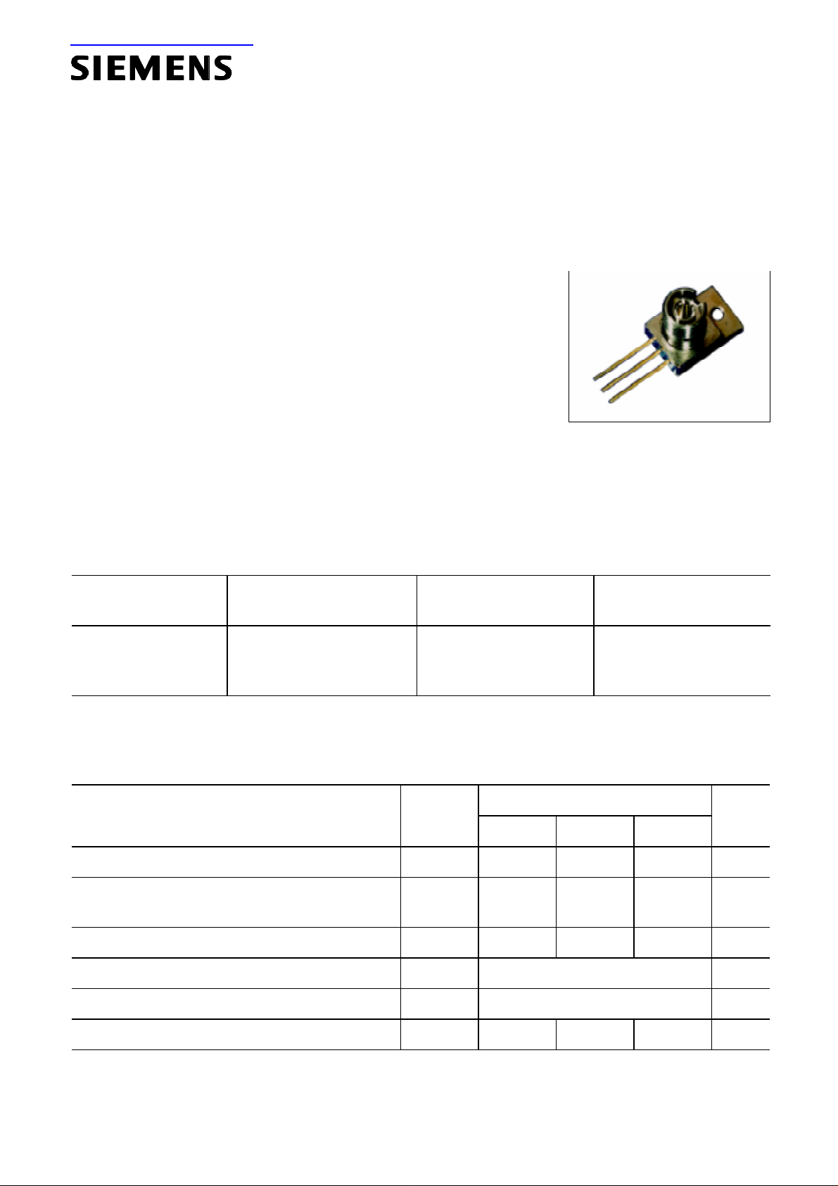
Laser Diode in TO-220 Package with FC-connector SPL 2Fxx
0.75 W cw (Class 4 Laser Product) (SFH 4874x6)
Features
•
Efficient radiation source for pulsed and cw-operation
•
Reliable InGa(Al)As strained quantum-well material
•
Small TO-220 package with efficient thermal coupling
•
Includes thermistor to control temperature/wavelength
•
Single emitting area 200 µm × 1 µm
•
FC-type connector for efficient fiber coupling
Applications
•
Pumping solid state lasers (Nd: YAG, Yb: YAG, …)
•
Medical applications
•
Laser soldering
•
Energy transmission
•
Testing and measuring applications
Type
Old Type
Wavelength
*)
(as of Oct. 1996)
SPL 2F81
SPL 2F85
SPL 2F94
*) Other wavelengths in the range of 780 nm ... 980 nm are available on request.
SFH 487406
SFH 487426
SFH 487446
808 nm
850 nm
940 nm
Maximum Ratings
T
(
= 25 °C)
A
Parameter
Symbol Values Unit
min. typ. max.
Output power (continuous wave)
1)
Output power (quasi-continuous wave)
t
(
≤ 150 µs, duty cycle ≤ 1%)
p
P
opt
1)
P
qcw
– – 0.8 W
– – 1.1 W
Ordering Code
Q62702-P368
Q62702-P1678
Q62702-P1631
Reverse voltage
Operating temperature
Storage temperature
Maximum soldering temperature, max. 5 s
1) Optical data refer to output after a fiber of 5 m length (core ∅ 125 µm, 0.35 NA, attn. 8 db/km)
V
R
T
op
T
stg
T
s
––3V
– 10 … + 60 °C
– 40 … + 70 °C
– – 250 °C
Semiconductor Group 1 02.97
Page 2
Diode Characteristics
(TA = 25 °C)
SPL 2Fxx
(SFH 4874x6)
Parameter
Emission wavelength
Spectral width (FWHM)
Output power
2)
1)
1)
Differential efficiency 2) 808 nm
850 nm
940 nm
Threshold current 808 nm
850 nm
940 nm
Operating current 1) 808 nm
850 nm
940 nm
Operating voltage
1)
Symbol Values Unit
min. typ. max.
λ
peak
803
840
935
808
850
940
813
860
945
nm
∆λ 2nm
P
opt
η 0.60
0.60
0.55
I
th
0.40
0.30
0.30
I
op
1.3
1.3
1.4
V
op
0.75 W
0.70
0.70
0.60
0.45
0.40
0.35
1.5
1.5
1.6
0.85
0.80
0.70
0.55
0.50
0.40
1.8
1.8
1.8
W/A
A
A
2.0 V
Differential series resistance r
Characteristic temperature (threshold)
3)
Temperature coefficient of current
Temperature coefficient of wavelength
4)
Thermal resistance (junction → heat sink) R
1) Standard operating conditions refer to 0.75 W after 5 m of fiber (core ∅ 125 µm, 0.35 NA, attn. 8 db/km)
2) Optical power measurements refer to output from fiber
3) Model for the thermal behavior of threshold current:
4) Depending on emission wavelength
s
T
0
∂
/ ∂
I
T 0.5 %/K
op
∂λ / ∂
T 0.25 0.27 0.30 nm/K
th JA
I
T
I
) =
2
T
(
th
) × exp(
1
(
th
0.2 0.4 Ω
150 K
10 K/W
T
T
T
–
)/
2
1
0
NTC Thermistor
Parameter
Resistance at room temperature (25 °C) R
Symbol Typ. Values Unit
NTC
10 kΩ
Semiconductor Group 2
Page 3
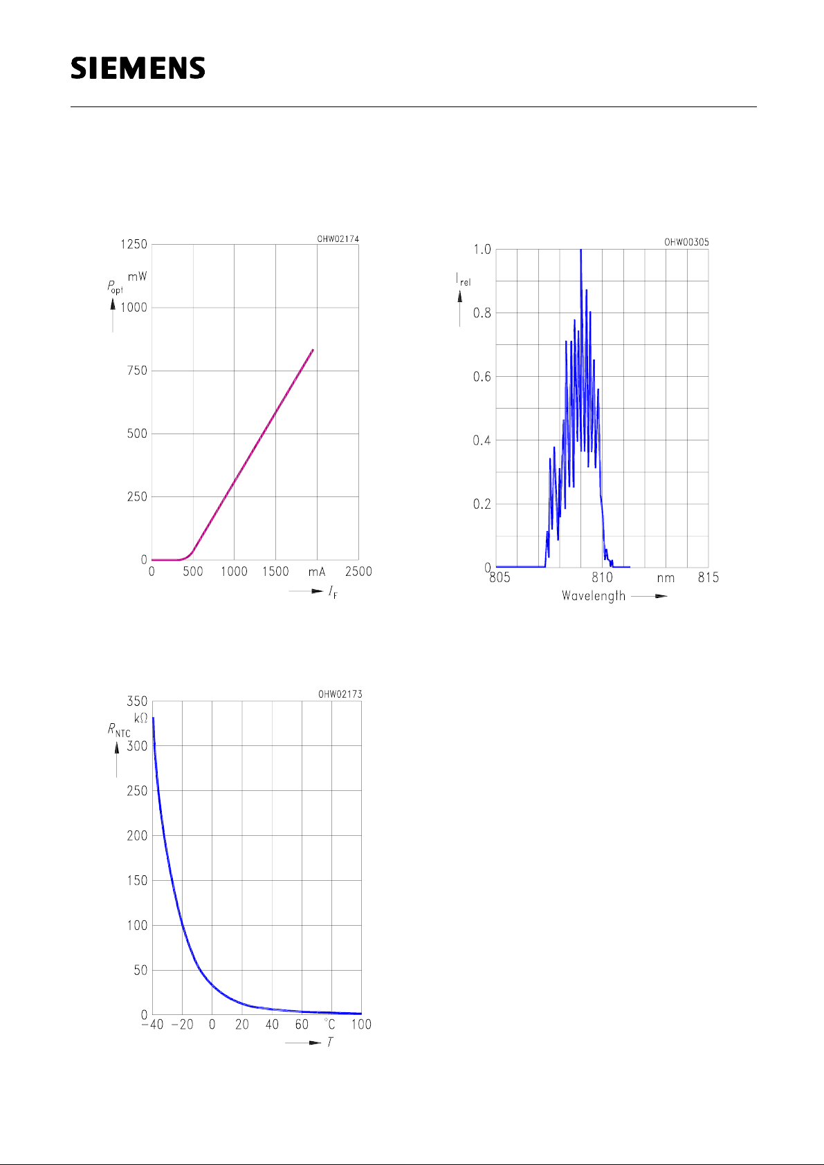
Optical Characteristics (TA = 25 °C)
SPL 2Fxx
(SFH 4874x6)
Radiant Power P
opt
vs I
F
Mode Spectrum I
vs λ (P
rel
= 1.0 W)
opt
NTC Thermistor R
R
= 10 kΩ ± 1%
T 25 °C
= f(T
)
Semiconductor Group 3
Page 4

SPL 2Fxx
(SFH 4874x6)
Notes for Operation
1. Eye Protection
This laser is a Class 4 Laser product.
Refer to the relevant safety regulations for protection during handling and operation.
2. Overload Protection
The specified values are valid as long as the diode has not been not overloaded. Voltage
spikes from the power supply unit, even when applied for nanoseconds only, may cause irreversible damage to the laser diode. Such spikes may occur when the power supply is turned
on or off, or they may reach the laser diode from the line via the coupling capacitance of
electronically controlled devices.
The power supply should therefore be provided with appropriate protection circuits.
Handling Notes
1. Package
To avoid electrostatic damage it is recommended to observe the same rules as for handling
MOS-devices.
2. Mechanical Attachment
2.1 Mounting hole (suitable for M 2.5)
Because of the good thermal conductivity of the TO 220 base plate (copper) the heat
loss is properly dissipated even if the component is attached on one side only. Some
mounting techniques are shown below (Fig. 1 – 3).
2.2 For exact positioning of the TO component and other parts, e.g. lenses, the TO 220
package can be attached with appropriate clamping devices or screws (max. M 2.5).
3. Soldering
When soldering the TO base to a heat sink, do not exceed the following limits:
• max. soldering temperature: 125 °C
• max. soldering time: 1 min.
Semiconductor Group 4
Page 5
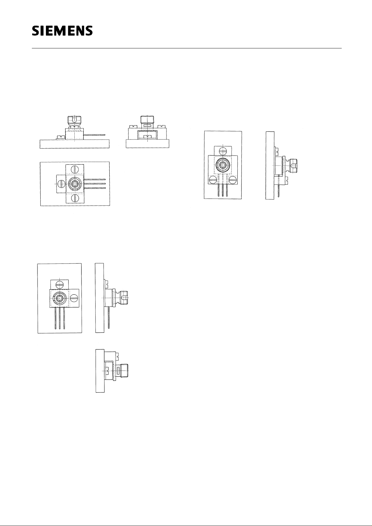
Mounting Techniques
SPL 2Fxx
(SFH 4874x6)
Figure 1
Figure 2
Figure 3
Semiconductor Group 5
Page 6
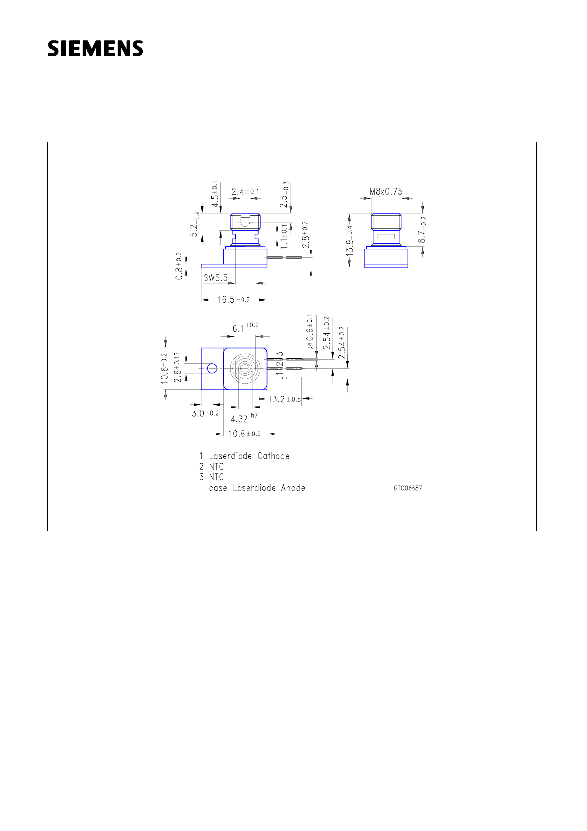
Package Outlines
(Dimensions in mm, unless specified).
SPL 2Fxx
(SFH 4874x6)
Semiconductor Group 6
 Loading...