

Page 1
Corporation
SP682
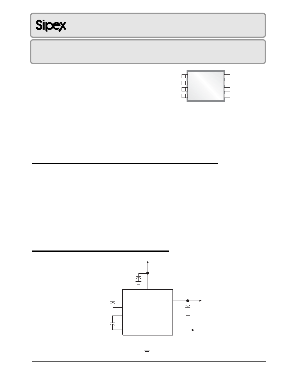
Micro Power Inverting Charge Pump
■ Low Power Voltage Conversion
■ +2.4V to +5.5V Input Range
■ 99% Voltage Conversion Efficiency
■ Typical 60µA Supply Current
1
C1-
C2+
C2-
V
OUT
2
3
4
SP682
8 Pin MSOP
8
SD
7
C1+
V
6
CC
GND
5
■ Requires Only Three External Capacitors
■ Includes Low Power Shutdown Option
Now Available in Lead Free Packaging
■ Ideal in Portable Applications Such As
Handheld Instruments
Cellular Phones
Personal Digital Assistants
Laptops and Notebooks
■ Pin Compatible Upgrade to Microchip's
TC682
APPLICATIONS
■ LCD Display
■ Negative bias supply for op amps
■ Serial interface protocol circuits
DESCRIPTION
The SP682 is a monolithic charge pump voltage converter that produces a doubled, negative
voltage from a single positive supply. The SP682 charge pump outputs a –10V voltage from
a +5V input. Three external charge pump capacitors are required to support the voltage
conversion and voltage doubling process. An internal oscillator generates a 12kHz clock
which cycles the internal switching that charges the storage and transfer capacitors. The
charge pump architecture is fabricated using a low power BiCMOS process technology.
The SP682 charge pump is ideal for low power applications requiring a typical +3V battery
source such as a lithium cell. Typical applications are handheld instruments, notebook and
laptop computers, cellular phones, and data acquisition or GP systems. The SP682 is
packaged in either 8-pin NSOIC, 8-pin MSOP for surface mount applications, and 8 Pin PDIP.
+2.4V to +5V
TYPICAL APPLICATION CIRCUIT
1µF
+
6
V
7
C1
C2
Date: 11/29/04 SP682 Micro Power Inverting Charge Pump © Copyright 2004 Sipex Corporation
C1+
1
C1–
2
C2+
3
C2–
CC
SP682
GND
5
-
V
V
OUT
4
SD
8
OUT
C
OUT
1
Page 2
ABSOLUTE MAXIMUM RATINGS
These are stress ratings only and functional operation
of the device at these ratings or any other above those
indicated in the operation sections of the specifications
below is not implied. Exposure to absolute maximum
rating conditions for extended periods of time may
affect reliability.
VCC...........................................................................+7V
........................................................................–11V
V
OUT
Storage Temperature..........................-65˚C to +150˚C
Power Dissipation:
8-pin NSOIC......................................500mW
8-pin MSOP......................................320mW
8-pin PDIP......................................750mW
Package Derating:
8-pin NSOIC:
..................................................128 °C/W
ø
8-pin MSOP:
JA
øJA..................................................216°C/W
8-pin PDIP:
ø
..................................................97°C/W
JA
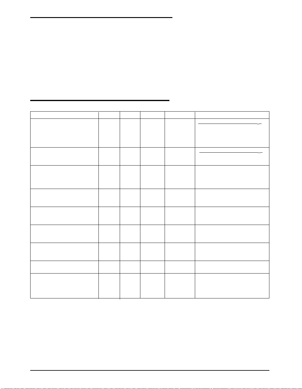
ELECTRICAL CHARACTERISTICS
TA = T
to T
and VCC = +5V. Charge pump cap = 3.3µF, unless otherwise noted.
MIN
MAX
SUPPLY CURRENT CHARGE PUMP CAPACITORS: 3.3µF
I
CC
in shutdown 1 µATA = +25OC, SD = +5V
CHARGE PUMP OUTPUT CHARGE PUMP CAPACITORS: 3.3µF
V
OUT
SOURCE RESISTANCE
R
OUT
OSCILLATOR FREQUENCY
f
OSC
MIN. TYP. MAX. UNITS CONDITIONS
60 120 µARL = ∞, TA = +25°C
200 µARL = ∞
–9.9 –9.99 Volts RL = ∞
–9.0 –9.5 Volts RL = 2kΩ
140 180 Ω IL = 10mA, TA = +25°C
230 Ω IL = 10mA
380 450 Ω IL = 5mA, VCC = +2.8V
12 20 kHz f
= 2 X f
osc
C1+
CONVERSION EFFICIENCY
V
OUT EFF
V
OUT EFF
99 99.9 % RL = ∞
90 95 % RL = 2kΩ
START-UP TIMING
V
Power On Delay 12 ms RL = 2kΩ
OUT
SHUTDOWN TIMING
Shutdown to V
Delay 5 ms RL = 2kΩ
OUT
SUPPLY VOLTAGE
V
CC
Operating Temperature Range
- C 0 +70
- E -40 +85
Date: 11/29/04 SP682 Micro Power Inverting Charge Pump © Copyright 2004 Sipex Corporation
+2.4 +5.5 Volts
o
o
C
C
2
Page 3
THEORY OF OPERATION
The SP682's charge pump design is a simplified version of Sipex's original patented charge
pump design (5,306,954) except that it only
generates a negative output. The charge pump
utilizes external capacitors to store the charge.
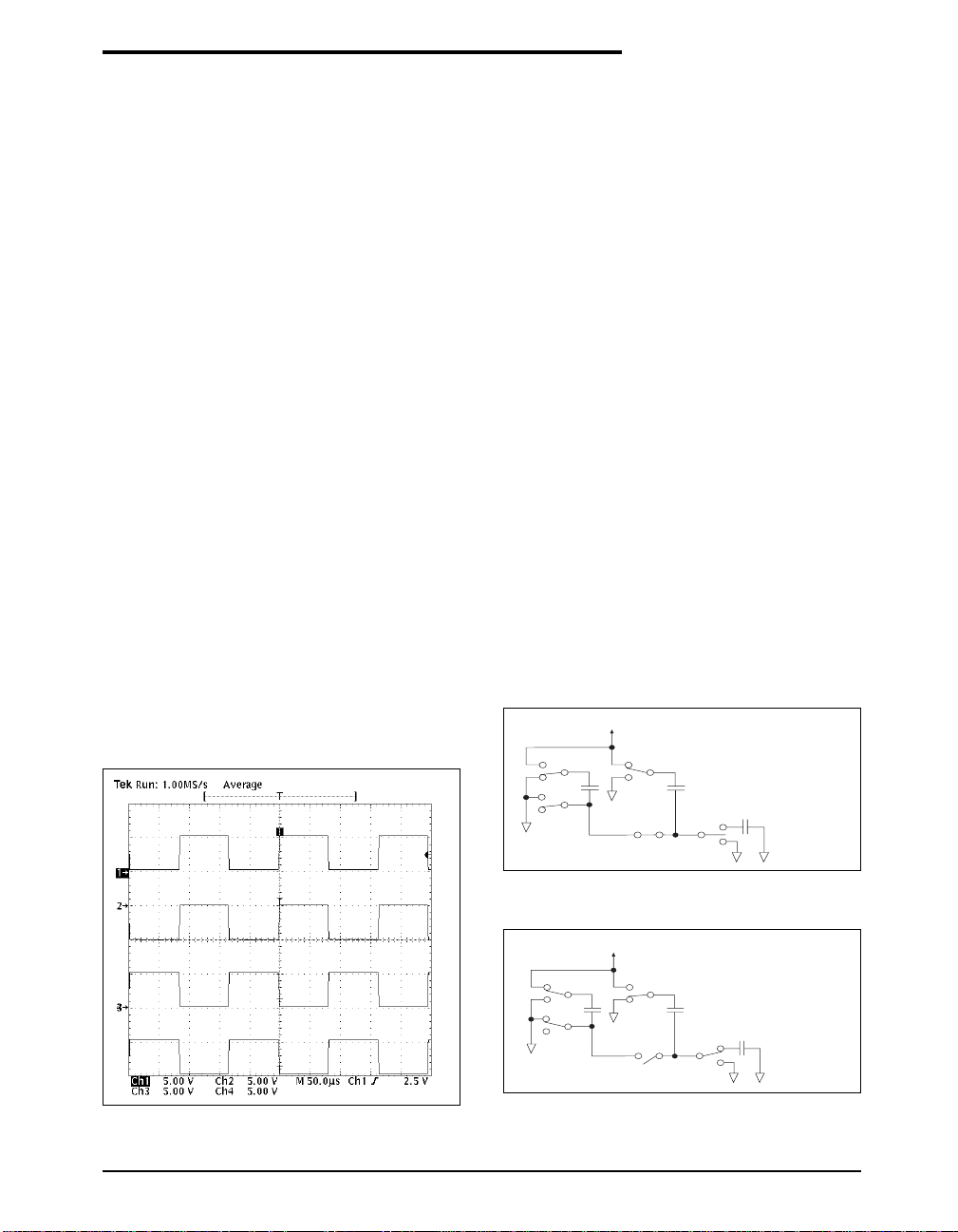
Figure 1 shows the waveform found on the
negative side of capacitor C2. There is a free–
running oscillator, running at 12kHz, that controls the two phases of the voltage shifting. A
description of each phase follows.
Phase 1
V
charge storage — During this phase of
OUT
the clock cycle, the positive side of capacitors
C1 and C2 are initially charged to +5V. C
then switched to ground and the charge on C
is transferred to C
+5V, the voltage potential across capacitor C
–
. Since C
2
+
is connected to
2
+
is
l
is now 10V.
Phase 2
V
transfer — Phase two of the clock con-
OUT
nects the negative terminal of C2 to the V
storage capacitor and the positive terminal of
OUT
C2 to ground, and transfers the generated –l0V
to C3. Simultaneously, the positive side of
capacitor C 1 is switched to +5V and the negative side is connected to ground.
The oscillator frequency or clock rate for the
charge pump is designed for low power operation. The oscillator operates at a frequency of
about 12kHz (20kHz maximum) which conserves power as opposed to higher frequency
which operation typically draws more power
from VCC. The external charge pump capacitors
specified are 3.3µF but the absolute minimum
should be 1µF.
EFFICIENCY INFORMATION
A charge pump theoretically produces a doubled
voltage at 100% efficiency. However in the real
world, there is a small voltage drop on the output
which reduces the output efficiency. The SP682
can usually run 99.9% efficient without driving
a load. While driving a 1kΩ load, the SP682
remains over 90% efficiency.
–
1
2
Output Voltage Efficiency = V
V
= –2*VCC + V
OUT
V
= (I
OUT
)*(R
OUT
OUT
*(V
DROP
Power Loss = I
OUT
DROP
)
DROP
The efficiency changes as the external charge
pump capacitors are varied. Larger capacitor
values will strengthen the output and reduce
output ripple. Although smaller capacitors will
cost less and save board space, lower values will
reduce the output drive capability and also increase the output ripple.
VCC = +5V
++
C
1
–5V
+5V
C
2
––
–5V
/ (–2*VCC);
)
V
Storage Capacitor
OUT
+
–
C
3
Figure 2. Charge Pump Phase 1
VCC = +5V
++
C
1
Figure 1. Charge Pump Waveform
Date: 11/29/04 SP682 Micro Power Inverting Charge Pump © Copyright 2004 Sipex Corporation
Figure 3. Charge Pump Phase 2
C
2
––
–10V
V
Storage Capacitor
OUT
+
–
C
3
3
Page 4
THEORY OF OPERATION
The ESR of the charge pump capacitors also
determine the output resistance. Assuming that
switch resistances are approximately equal, the
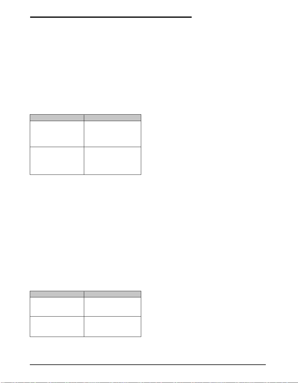
output resistance can be derived as shown below:
R
= 16*(R
OUT
+ 1 / (f
R
is typically 140Ω at +25°C with VCC at
OUT
+5V using 3.3µF capacitors. The total internal
) + 4*( ESRC1+ ESRC2) + ESR
SW1-4
* C1) + 1 / (f
OSC
OSC
* C2)
C3
switch resistance (16*RSW) is approximately
90Ω. The table below shows the comparison of
R
versus C1&C2.
OUT
C1, C2 (µF) ROUT (Ω)
0.05 4085
0.10 2084
0.47 510
1.00 285
3.30 140
4.70 125
10.00 105
22.00 94
Table 1. R
.vs. C1, C2
OUT
The output voltage ripple is also affected by the
capacitors, specifically C
will reduce the output ripple for a given output
. Larger values
OUT
current load of current. The formula representation is:
SHUTDOWN FEATURE
The SP682 charge pump includes a shutdown
feature (pin 8) which disables the charge pump
when the V
activate the shutdown mode. If shutdown is not
is not needed. A logic "1" will
OUT
needed, it can be left open where an internal
pull-down resistor will always keep the charge
pump active. Typical input current for the
shutdown pin is 3µA. The shutdown feature is
another option for conserving power in portable
applications, reducing current to only 1µA.
PARALLEL DEVICES
Multiple SP682 charge pumps can be connected
in parallel. However, the effective output resistance now is the output resistance of a single
device divided by the number of devices. Connecting multiple pumps allows the user to save
on the storage capacitor. The charge pump
capacitors still must be separate for each device.
APPLICATIONS INFORMATION
The SP682 charge pump produces a doubled,
inverted voltage from the VCC input. As such, it
can serve in many applications where a negative
–5V to –10V output is needed. Typical applications include powering analog switches, and
biasing LCD displays and panels.
V
= {1 / [2 * (f
RIPPLE
To minimize the output ripple, the C
capacitor can be increased to over 10µF whereas
* C3)] + 2 * (ESRC3)} * I
OSC
OUT
OUT
storage
the pump capacitors can range from 1µF to 5µF.
Table 2 shows the typical V
C
values.
OUT
C
(µF) V
OUT
0.50 1020
1.00 520
3.30 172
4.70 120
10.00 70
22.00 43
Table 2. C3 .vs. V
Date: 11/29/04 SP682 Micro Power Inverting Charge Pump © Copyright 2004 Sipex Corporation
RIPPLE
RIPPLE
RIPPLE
for given
(mV)
4
Page 5
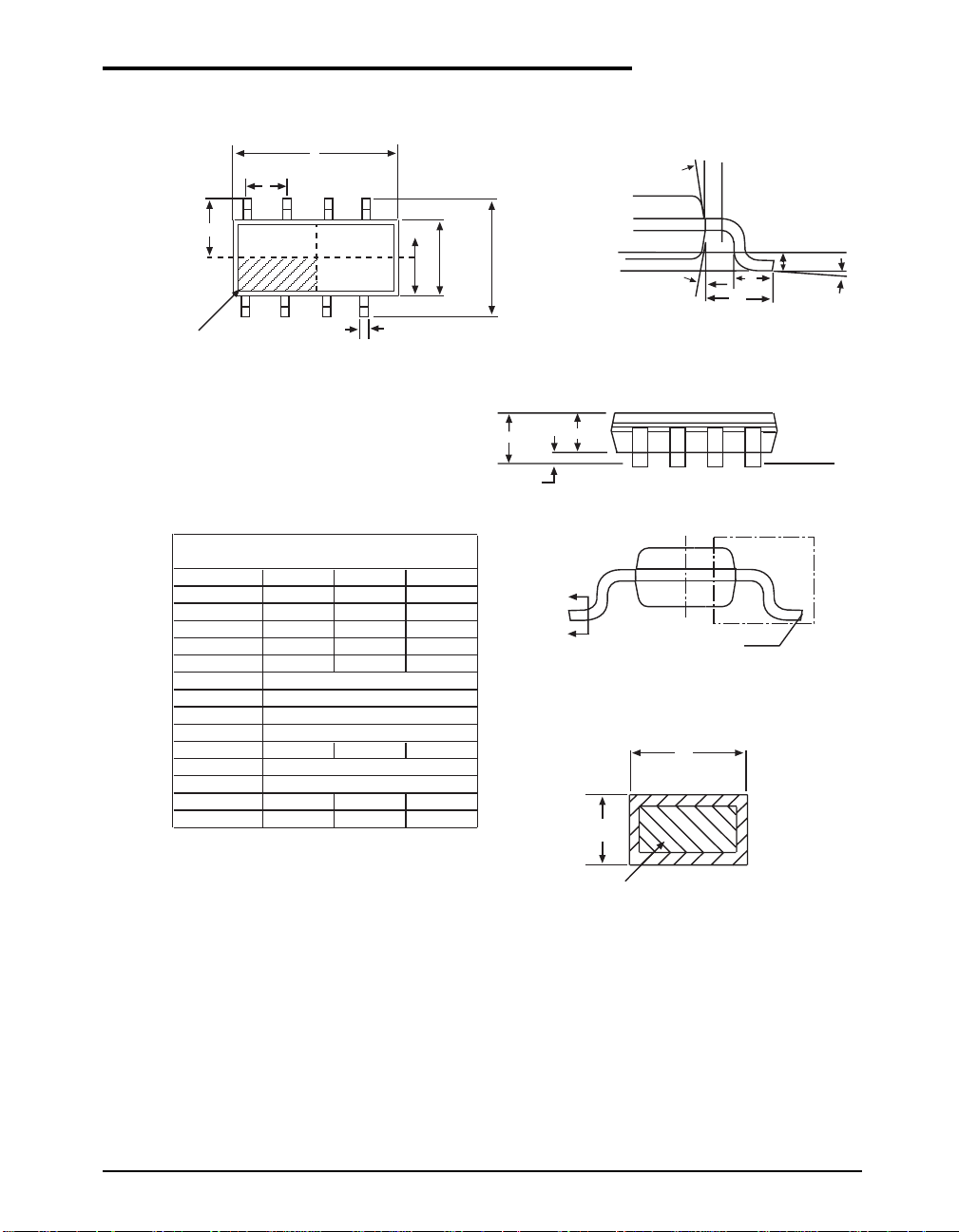
E/2
PACKAGE: 8 PIN NSOIC
D
e
Ø
INDEX AREA
(D/2 X E1/2)
1
TOP VIEW
8 Pin NSOIC JEDEC MO-012 (AA) Variation
SYMBOL
MIN NOM MAX
A1.35-1.75
A1 0.1 - 0.25
A2 1.25 - 1.65
b0.31-0.51
c0.17-0.24
D
E
E1
e
4.90 BSC
6.00 BSC
3.90 BSC
1.27 BSC
L0.4-1.27
L1
L2
1.04 REF
0.25 BSC
ø0º-8º
ø1 5º - 15º
Note: Dimensions in (mm)
E1
E1/2
b
E
Seating Plane
Ø1
L1
VIEW C
A
A1
A2
B
B
SIDE VIEW
SEE VIEW C
b
c
L
L2
Gauge Plane
Seating Plane
Ø
BASE METAL
SECTION B-B
WITH PLATING
Date: 11/29/04 SP682 Micro Power Inverting Charge Pump © Copyright 2004 Sipex Corporation
5
Page 6
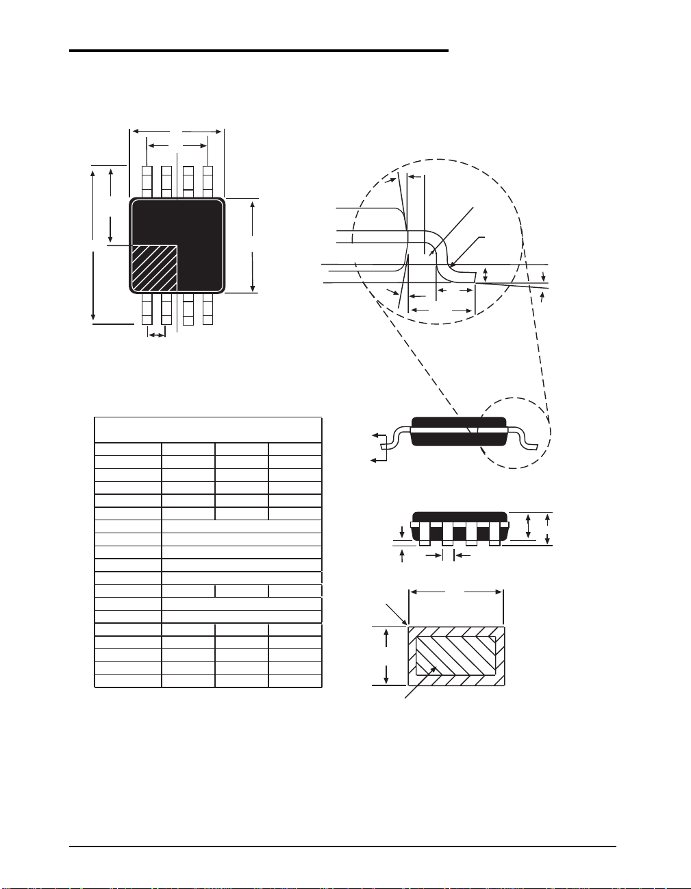
E/2
PACKAGE: 8 PIN MSOP
D
e1
Ø1
R1
E
E1
Seating Plane
2
1
Pin #1 indentifier must be indicated within this shaded area (D/2 * E1/2)
e
8 Pin MSOP JEDEC MO-187 (AA) Variation
SYMBOL
MIN NOM MAX
A--1.1
A1 0 - 0.15
A2 0.75 0.85 0.95
b 0.22 - 0.38
c 0.08 - 0.23
D
E
E1
e
e1
3.00 BSC
4.90 BSC
3.00 BSC
0.65 BSC
1.95 BSC
L 0.4 0.6 0.8
L1
L2
0.95 REF
0.25 BSC
N-8R 0.07 - -
R1 0.07 - -
ø0º-8º
ø1 0º - 15º
Note: Dimensions in (mm)
B
B
WITH PLATING
BASE METAL
R
A2
Gauge Plane
Ø
A
L2
Ø1
A1
c
L
L1
b
b
Section B-B
Date: 11/29/04 SP682 Micro Power Inverting Charge Pump © Copyright 2004 Sipex Corporation
6
Page 7
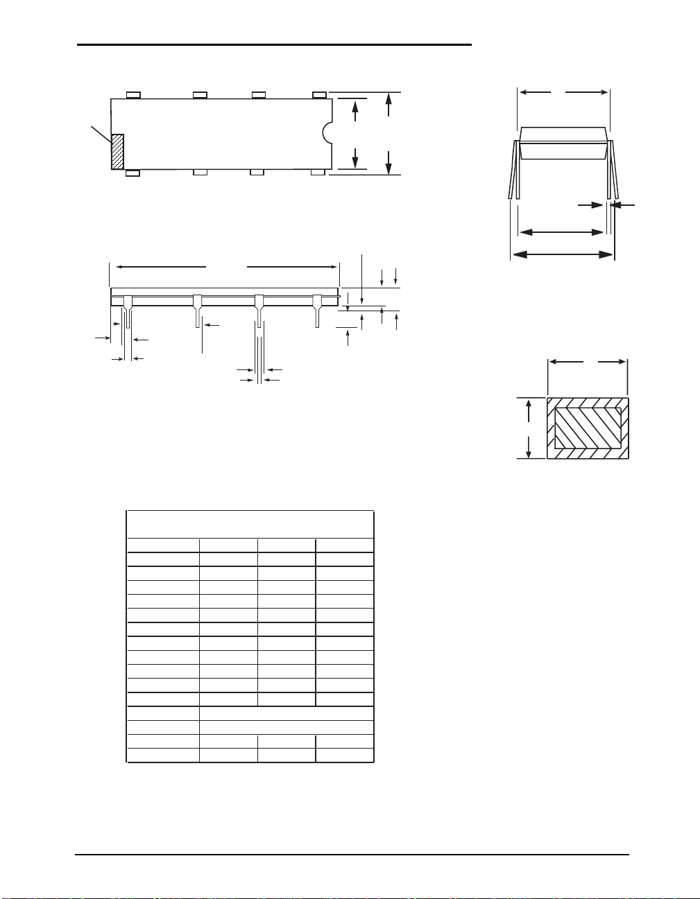
PACKAGE: 8 PIN PDIP
INDEX
AREA
D1
N
E
E1
1
b3
23
D
e
N/2
A1
A
A2
L
b2
E
c
eA
eB
b
b
c
8 PIN PDIP JEDEC MS-001 (BA) Variation
SYMBOL MIN NOM MAX
A--0.21
A1 0.15 - A2 0.115 0.13 0.195
b 0.014 0.018 0.022
b2 0.045 0.06 0.07
b3 0.3 0.039 0.045
c 0.008 0.01 0.014
D 0.355 0.365 0.4
D1 0.005 - -
E 0.3 0.31 0.325
E1 0.24 0.25 0.28
e
eA
.100 BSC
.300 BSC
eB - - 0.43
L 0.115 0.13 0.15
Note: Dimensions in (mm)
Date: 11/29/04 SP682 Micro Power Inverting Charge Pump © Copyright 2004 Sipex Corporation
7
Page 8
ORDERING IFORMATION
Part Number Temperature Range Package Types
SP682CN............................................. -0°C to +70°C ................................................................. 8-pin NSOIC
SP682CN/TR....................................... -0°C to +70°C .................................................................8-pin NSOIC
SP682CP............................................. -0°C to +70°C .................................................................... 8-pin PDIP
SP682CU............................................. -0°C to +70°C .................................................................. 8-pin MSOP
SP682CU/TR....................................... -0°C to +70°C ..................................................................8-pin MSOP
SP682EN........................................... -40°C to +85°C ................................................................. 8-pin NSOIC
SP682EN/TR ..................................... -40°C to +85°C ................................................................. 8-pin NSOIC
SP682EP ........................................... -40°C to +85°C .................................................................... 8-pin PDIP
SP682EU........................................... -40°C to +85°C .................................................................. 8-pin MSOP
SP682EU/TR ..................................... -40°C to +85°C ..................................................................8-pin MSOP
/TR = Tape and Reel
Pack quantity is 2,500 for NSOIC and MSOP.
CLICK HERE TO ORDER SAMPLES
Corporation
ANALOG EXCELLENCE
Sipex Corporation
Headquarters and
Sales Office
233 South Hillview Drive
Milpitas, CA 95035
TEL: (408) 934-7500
FAX: (408) 935-7600
Sipex Corporation reserves the right to make changes to any products described herein. Sipex does not assume any liability arising out of the
application or use of any product or circuit described hereing; neither does it convey any license under its patent rights nor the rights of others.
Date: 11/29/04 SP682 Micro Power Inverting Charge Pump © Copyright 2004 Sipex Corporation
8
 Loading...