

Page 1

®
High Efficiency Charge Pump Regulator
FEATURES
■ Ideal For White LED Driver
■ Low Profile, Inductorless Regulator
■ X1.5 and X2 Modes for Highest Efficiency
■ +2.7V to +5.5V Input Voltage Range
■ Fast Turn-On Time, 175µS
■ 1mA Quiescent Current
■ <1.5µA Shutdown Current
■ Built-in 600kHz Oscillator
■ Programmable Output Current or Voltage
■ PWM Dimming Control with Enable Pin
■ Shutdown to Disconnect Output from Input
■ Soft Start to Eliminate In-Rush Current
■ Industry Standard 10-pin MSOP Package
and Small 10-pin DFN Package
SP6682
for White LEDs
V
1
OUT
C1P
2
FB
IN
SP6682
3
10 Pin DFN
4
5
V
MODE
V
Now Available in Lead Free Packaging
APPLICATIONS
■ Next Generation Mobile Phones
■ PDAs
■ 3.3V to 5.0V Conversion
■ Digital Still Cameras
■ Digital Camcorders
■ Palmtop Computers
■ Color LCD Modules
10
9
8
7
6
C2P
C1N
GND
C2N
EN/PWM
DESCRIPTION
The SP6682 is a current regulated charge pump ideal for converting a Li-Ion battery input for
driving white LED used in backlighting color displays. The charge pump automatically switches
between X1.5 and X2 modes based on the input voltage, providing improved efficiency over
traditional methods using charge pump doubler followed by LDO. This input voltage threshold
can be externally programmed for optimized efficiency at specific output voltages and currents.
The SP6682 operates with an internal 600kHz clock, enabling the use of small external
components. Output current or voltage can be accurately regulated by modulating the switcher
between the charge pump and output capacitor. In shutdown mode, the IC disconnects the output
from the input and draws less than 1.5µA current. The SP6682 is offered in a 10-pin MSOP
package, and a small 10-Pin DFN Package.
TYPICAL APPLICATION SCHEMATIC
SP6682
®
C2P
C1N
GND
C2N
EN/PWM
10
9
8
7
6
C2
2.7 - 4.2V
Lithium-Ion
ENABLE/PWM DIMMING
Date: 03/04/05 SP6682, High Efficiency Charge Pump Regulator for White LEDs © Copyright 2005 Sipex Corporation
2.2µF
C1
2.2µF
R1
R2
R3
1M
1
2
3
4
5
C3
0.1µF
V
C1P
V
V
FB
OUT
IN
MODE
C4
2.2µF
C6
0.1µF
C5
2.2µF
White
LED
R6
20
20
20
20
1
Page 2
ABSOLUTE MAXIMUM RATINGS
VIN, V
VIN - V
Output Current (I
Power Dissipation per Package - 10-pin MSOP
(derate 8.84mW/°C above +70°C) ................. 720mW
Junction Temperature .................................... +125°C
Storage Temperature ...................... -65°C to +150°C
ESD Rating. ................................................ 2kV HBM
, V
MODE
OUT
and EN/PWM................. -0.3V to 6V
OUT
........................................................... 0.7V
) ...................................... 300mA
OUT
These are stress ratings only and functional operation of
the device at these ratings or any other above those
indicated in the operation sections of the specifications
below is not implied. Exposure to absolute maximum
rating conditions for extended periods of time may affect
reliability.
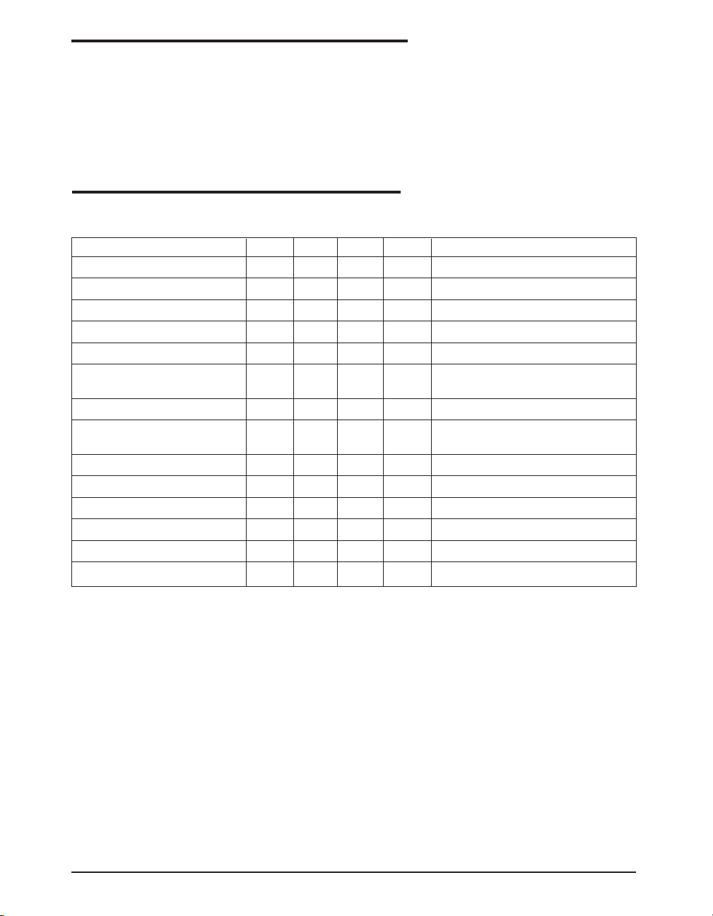
ELECTRICAL CHARACTERISTICS
Unless otherwise specified: VIN =+2.7V to +5.0V, C1=C2=C4=C5=2.2µF (ceramic, ESR=0.03Ω), C3=0.1µF
(ceramic) and T
PARAMETER MIN TYP MAX UNITS CONDITIONS
Input Voltage 2.7 5.5 V
Quiescent Current 1.2 3 mA V
Shutdown Current 1.5 µA EN/PWM = 0V, VIN = 5.5V
Oscillator Frequency 0.42 0.60 0.78 MHz VIN = 3.6V
V
Reference Voltage 0.275 0.306 0.337 V
FB
Charge Pump Output 11 18 Ω FB = 0V, VIN = 3.6V,
Resistance I
V
Threshold Voltage 1.15 1.25 1.35 V VIN Falling @ 25°C
MODE
Hysteresis for Mode Transition 30 mVPPVIN = 3.6V @ 25°C
Voltage
V
Pin Current 0.01 0.5 µAV
MODE
EN/PWM Logic Low 0.4 V
EN/PWM Logic High 1.6 V
EN/PWM Pin Current 0.01 0.5 µAV
FB Pin Current 0.5 µAVFB = 1V
V
Turn-On Time 175 500 µsVIN = 3.6V, FB within 90% regulation
OUT
=-40°C to +85°C unless otherwise noted.
AMB
= 4.2V, V
IN
= 20mA, V
OUT
= 1.25
MODE
EN/PWM
OUT
= 4.2V
= 3.6V, I
= High
MODE
= 100µA
OUT
Date: 03/04/05 SP6682, High Efficiency Charge Pump Regulator for White LEDs © Copyright 2005 Sipex Corporation
2
Page 3

PIN DESCRIPTION
PIN NUMBER PIN NAME DESCRIPTION
1V
OUT
Regulated charge pump output.
2 C1P Positive terminal to the charge pump flying capacitor C2.
3VINInput pin for the 2.7V to 5.5V supply voltage.
4V
MODE
Charge pump mode program pin. When V
is greater than 1.25V,
MODE
X1.5 charge pump is used. Otherwise, charge pump switches to X2
mode. A voltage divider shown in typical application circuit programs
the VIN threshold for charge pump mode switching.
5FBThis is the feedback pin for output current or voltage regulation. The
voltage of this pin is compared with an internal 306mV reference.
6 EN/PWM Enable and PWM dimming control input. Pull this pin low to discon-
nect V
from VIN and shutdown the SP6682.
OUT
7 C2N Negative terminal to the charge pump flying capacitor, C4.
8 GND Ground reference.
9 C1N Negative terminal to the charge pump flying capacitor, C2.
10 C2P Positive terminal to the charge pump flying capacitor C4.
FUNCTIONAL DIAGRAM
V
IN
C1P
C1N
C2P
C2N
V
OUT
V
OUT
COMP
600 kHz
Clock
Manager
Mode Control
GND
Start-up
and
Charge
Pump
Switches
MODE
COMP
Voltage
Referenc
306m
EN/PW
1.25V
V
MODE
FB
Date: 03/04/05 SP6682, High Efficiency Charge Pump Regulator for White LEDs © Copyright 2005 Sipex Corporation
3
Page 4
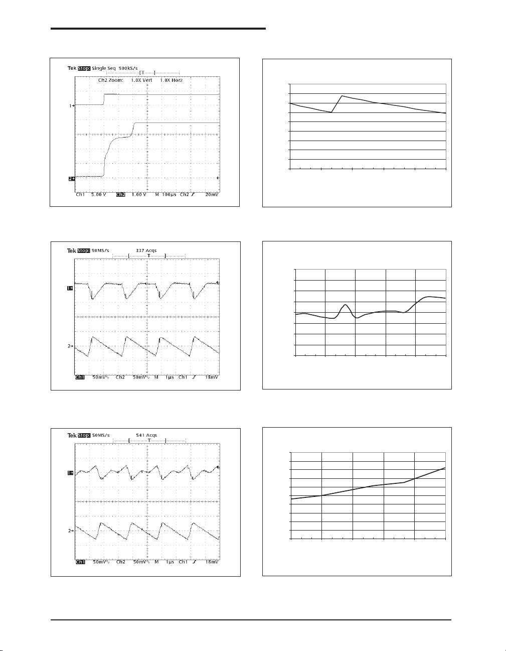
Refer to the typical application circuit, T
PERFORMANCE CHARACTERISTICS
= 25°C, IO = 60mA unless otherwise specified.
AMB
EN/PWM
V
OUT
Figure 1. Output voltage turn-on time
V
IN
V
OUT
5V/DIV
1V/DIV
50mV/DIV
50mV/DIV
90
80
70
60
50
40
Efficiency (%)
30
20
10
0
2.7 3 3.3 3.6 3.9 4.2
Input Voltage(V)
Figure 2. Power efficiency vs. input voltage
0.34
0.33
0.32
0.31
(V)
0.3
FB
V
0.29
0.28
0.27
0.26
2.7 3 3.3 3.6 3.9 4.2
V
(V)
Figure 3. X2 mode voltage ripple when VIN = 2.7V
V
IN
V
OUT
50mV/DIV
50mV/DIV
Figure 4. Feedback pin voltage vs. input voltage
1
0.9
0.8
0.7
0.6
(mA)
0.5
0.4
SUPPLY
I
0.3
0.2
0.1
0
2.7 3 3.3 3.6 3.9 4.2
V
(V)
Figure 5. X1.5 mode voltage ripple when VIN = 3.3V Figure 6. Quiescent current vs. input voltage
Date: 03/04/05 SP6682, High Efficiency Charge Pump Regulator for White LEDs © Copyright 2005 Sipex Corporation
4
Page 5
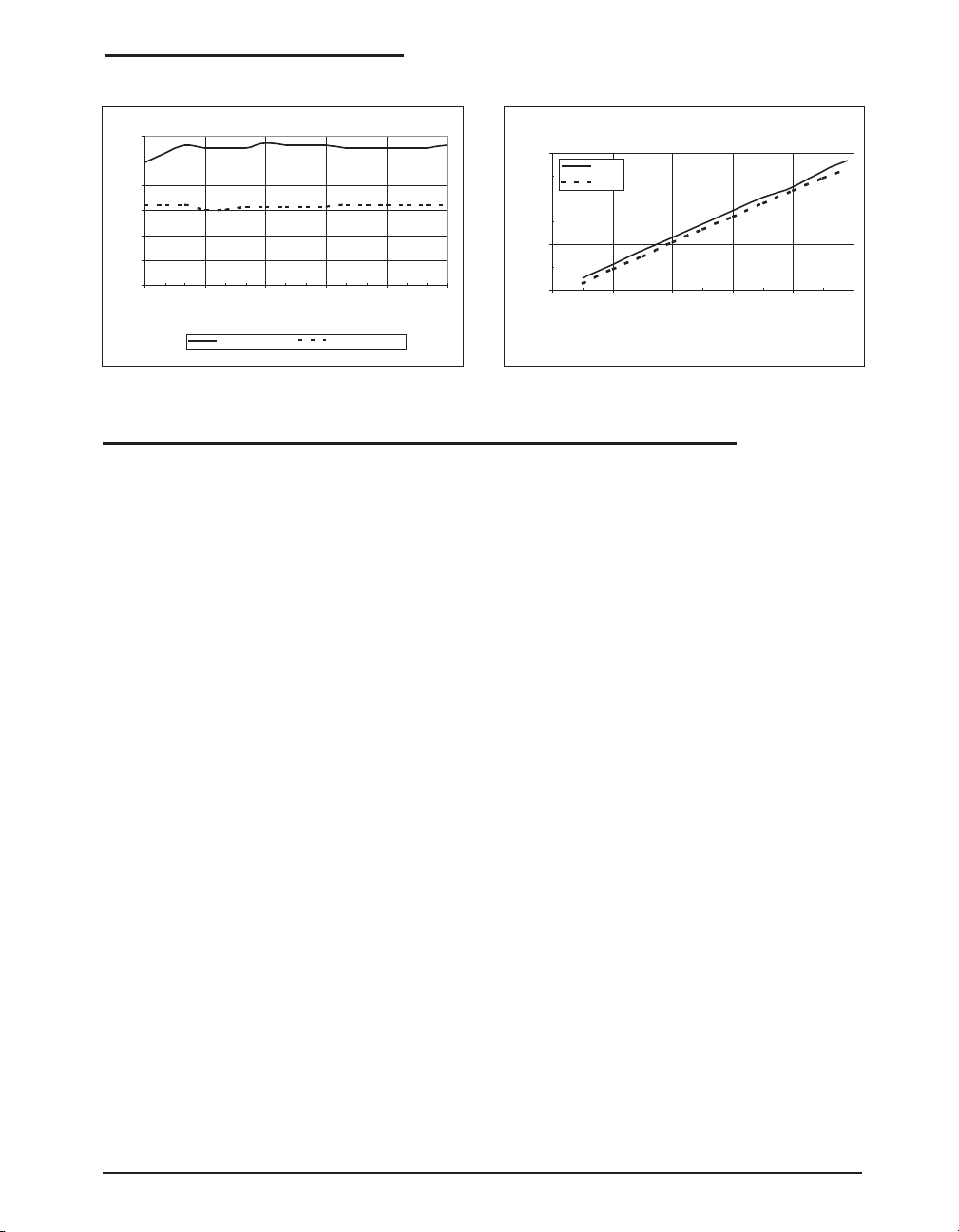
Refer to the typical application circuit, T
PERFORMANCE CHARACTERISTICS: Continued
= 25°C, IO = 60mA unless otherwise specified.
AMB
6
5
4
3
2
1
Brightness (kcd/m2)
0
2.7 3 3.3 3.6 3.9 4.2
Figure 7. Brightness vs. input voltage
Input Voltage (V)
4 LED's @ 30mA 4 LED's @ 15mA
General Overview
The SP6682 is a current regulated charge pump
ideal for converting a Li-Ion battery input for
driving white LEDs used in backlighting color
displays in cellular phones, PDAs, digital cameras and MP3 players. The SP6682’s proprietary AutoBoost feature enables the IC to automatically transition from X1.5 boost mode to
X2 boost mode based on battery input voltage
for optimal efficiency and performance. The
SP6682 is able to efficiently drive up to six
20mA white LEDs in parallel and maintain a
constant brightness over a very wide operating
voltage range (2.7V to 5.5V). The SP6682 operates with an internal 600kHz clock, enabling the
use of small external components. Other features of SP6682 include PWM dimming control
as well as complete input/out disconnect in
shutdown. In shut down mode the IC draws less
than 1.5µA current. The output regulation is
achieved by sensing the voltage at the feedback
pin and modulating the switcher between the
charge pump and output capacitor.
Theory of Operation
The SP6682 regulated charge pump block diagram consists of four main blocks (Voltage
Reference, Mode Control, Clock Manager, Startup and Charge-Pump Switches) and two com-
3
100 Hz
500 Hz
2
1
Brigtness, kCd/m2
0
020406080100
Figure 8. Brightness vs duty cycle
Duty Cycle,%
OPERATION
parators (V
Comparator and V
MODE
OUT
Com-
parator).
1) Voltage Reference. This block provides the
306mV and 1.25V reference voltages needed
for the two comparators.
2) Mode Control. An external voltage divider
connected to the V
pin will define an input
MODE
voltage to the mode comparator which sets the
logic state of the mode selection outputs to the
X2 or X1.5 modes. V
is compared to a
MODE
1.25V bandgap voltage. For example, if one
makes a 158K/100K divider, the mode will
change at 2.58 x 1.25 V =3.23V. A comparatorbased cycle by cycle regulation ensures that no
mode change occurs during cycles.
3) Clock Manager. An internal 600 kHz clock
is generated in this block. Depending on the
mode control, the appropriate clock phasing is
generated here and sent to the start-up and
charge-pump switches block.
4) Start-up and Charge Pump Switches. During start-up, until the reference is established,
this block keeps the charge pump inactive. During this period the output stays floating, by
consequence the charge pump drivers are now
referenced to V
occur (e.g. when VIN is ramped up to 4.2V, V
. Charging of the output will
OUT
OUT
ramps only up to about 3V), but not to the value
of VIN, protecting the White LED from experi-
Date: 03/04/05 SP6682, High Efficiency Charge Pump Regulator for White LEDs © Copyright 2005 Sipex Corporation
5
Page 6
OPERATION: Continued
encing high input voltages. Another important
operation of this block is the PWM/EN dimming control, which is implemented in the delay
of each pump driver, so that the enable high
pulse width is proportional to the delay of the
individual pump switches.
5) V
Comparator and Output Control. A
OUT
306mV reference voltage is compared to feed-
Configuring the SP6682 as Voltage or
Current Source
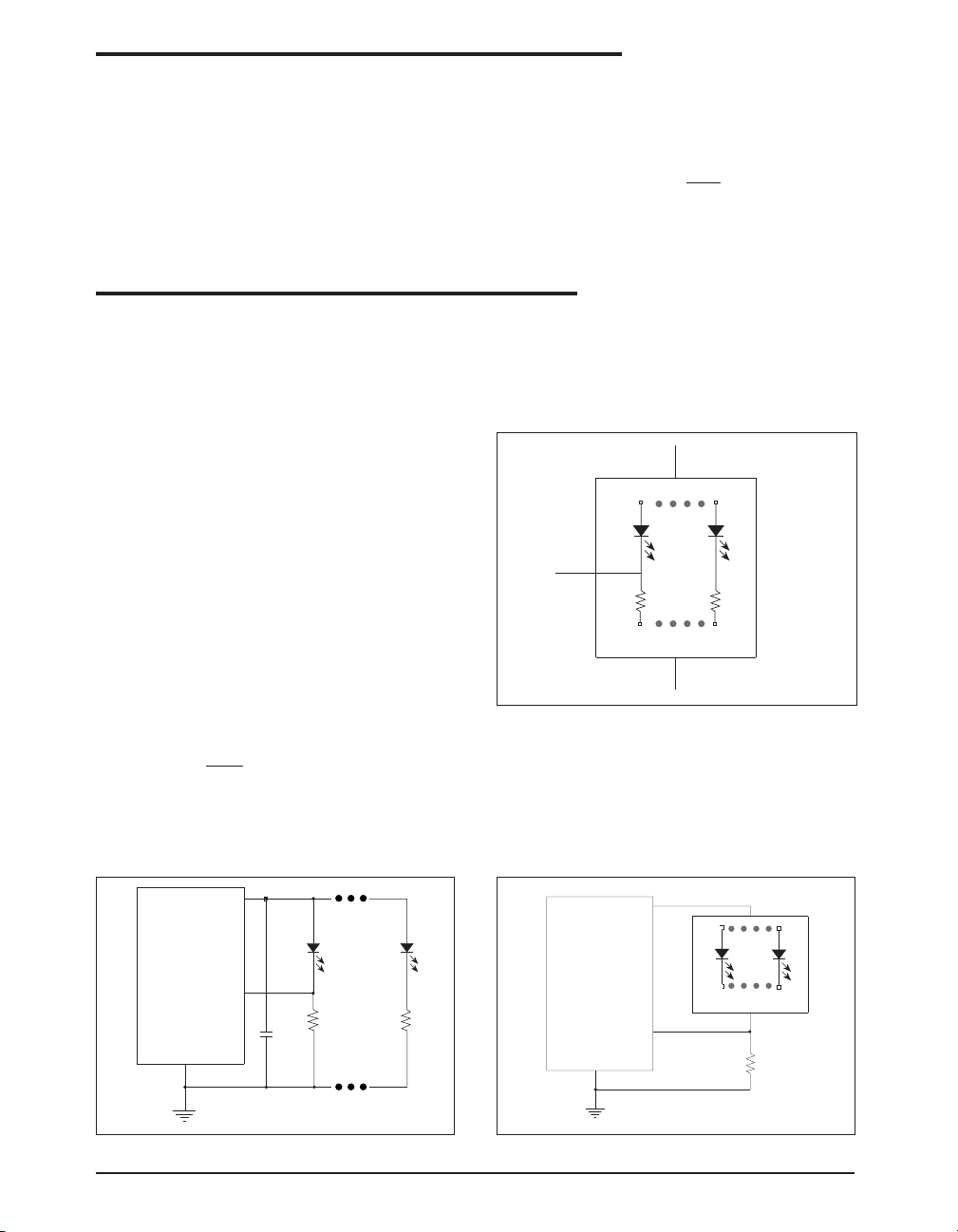
The white LED load configuration used by
customers can be discrete white LEDs or a white
LED module. Inside the white LED module,
there may or may not be resistors in series with
the white LEDs. According to the different
application requirements, the SP6682 can be
configured as either a voltage source or a current
source to provide solutions for these different
applications, as shown in figure 9~12. Figure 9
shows using the SP6682 to drive discrete white
LEDs as a current source.
The current in one white LED current is set by
the ratio of the feedback pin voltage (306mV)
and the bias resistor RB. To set the operating
current, RB can be selected by:
V
RB =
I
FB
LED
back output voltage to control the Vout needed
for the application. Output current is set by a
bias resistor from FB pin to GND pin chosen by
the relationship:
V
=
R
FB
FB
I
OUT
where VFB = 306mV.
APPLICATION INFORMATION
The current of the remaining white LEDs is set
according to the similarity of the white LEDs. 3wire white LED module with internal series
resistors as shown in figure 10 can also be driven
in this way.
Anode
FB
3-wire W-LED module
GND
Fig 10. 3-wire white LED module
In figure 11, SP6682 was used to drive a 2-wire
white LED module without internal series resistors as a current source. The bias resistor RB is
selected to regulate the total current of the white
LED module instead of the current of single
LED as in figure 9.
V
OUT
1
SP6682
5
FB
Rb
GND
8
Figure 9. Driving discrete white LEDs as current source
Date: 03/04/05 SP6682, High Efficiency Charge Pump Regulator for White LEDs © Copyright 2005 Sipex Corporation
2.2uF
Rb
Figure 11. Driving 2-wire white LED module as current
source
SP6682
GND
8
V
OUT
1
5
V
FB
Anode
2-wire W-LED module
Cathode
Rb
6
Page 7
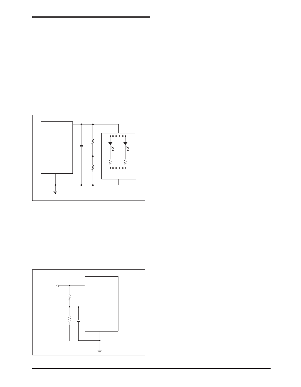
In this application, the bias resistor can be selected by:
V
FB
LED (TOTAL)
is the total operating current
where I
RB =
I
LED(TOTAL)
of all the white LEDs.
To use SP6682 as a voltage source for fixed
voltage applications, a voltage divider is need to
program the ouput voltage, as shown in figure 12.
The output voltage is set by the ratio of the two
APPLICATION INFORMATION: Continued
Programming the Operating Mode
SP6682 can automatically change from X1.5
mode to X2 mode for highest efficiency. To use
this feature, divider resistors should be chosen
according to the specific application, as shown
in figure 13.
The guideline for divider resistor selections is as
follows. For high input voltage, the SP6682 will
work in X1.5 mode. When the input voltage
drops to Vth threshold voltage, it will switch to
X2 mode automatically. The Vth threshold voltage for mode change can be calculated by:
V
OUT
1
R5
SP6682
V
FB
GND
8
Figure 12. Driving 2-wire white LED module as voltage
source
2.2uF
5
R6
Anode
2-wire W-LED
module
Cathode
resistors and the feedback control voltage as
shown by:
R
V
V
R
IN
SP6682
MODE
5
) • V
6
GND
FB
8
V
= ( 1 +
OUT
V
IN
Figure 13. Programming the Vmode Resistors
3
R1
4
R2
C2
VTH = (VF + 0.306 + m • I
LED
• R
OUT
)/1.5
Where VF and m are the forward voltage and
number of the white LEDs, Rout is the output
resistance of the SP6682.
The equation for the voltage divider R1 and R
with V
MODE
= 1.25V is:
VTH = 1.25V • (1+R1/R2)
which can be expressed as R1:
R1 = (V
/ 1.25 -1) • R
TH
2
For the typical SP6682 application, Using
VF=3.6V, m=4, I
=15mA, R
LED
=16Ω, the
OUT
VTH will be 3.24V. Select R2=100kΩ, then
R1=158kΩ.
Capacitor Selection
Ceramic capacitors are recommended for their
inherently low ESR, which will help produce
low peak to peak output ripple, and reduce high
frequency spikes.
The fly capacitor controls the strength of the
charge pump. Selection of the fly capacitor is a
trade-off between the output voltage ripple and
the output current capability. Decreasing the fly
capacitor will reduce the output voltage ripple
because less charge will be delivered to the
output capacitor. However, smaller fly capaci-
2
Date: 03/04/05 SP6682, High Efficiency Charge Pump Regulator for White LEDs © Copyright 2005 Sipex Corporation
7
Page 8

APPLICATION INFORMATION
tor leads to larger output resistance, thus decreasing the output current capability and the
circuit efficiency. Place all the capacitors as
close to the SP6682 as possible for layout.
Increasing the value of the input and output
Table: 1
SUGGESTED LOW ESR CAPACITORS
MANUFACTURERS/ PART NUMBER CAPACITANCE/ CAPACITOR/ ESR
TELEPHONE# VOLTAGE SIZE/TYPE AT 100kHz
TDK/847-803-6100 C2012X5R1A225K 2.2µF/10V 0805/X5R 0.030Ω
TDK/847-803-6100 C2012X5R0J475K 4.7µF/6.3V 0805/X5R 0.020Ω
MURATA/770-436-1300 GRM188R60J225KE01D 2.2µF/6.3V 0603/X5R 0.030Ω
MURATA/770-436-1300 GRM219R60J475KE01D 4.7µF/6.3V 0805/X5R 0.020Ω
Brightness Control Using PWM
capacitors could further reduce the input and
output ripple.
Refer to Table 1 for some suggested low ESR
capacitors.
Dimming control can be achieved by applying a
PWM control signal to the EN/PWM pin. The
brightness of the white LEDs is controlled by
increasing and decreasing the duty cycle of the
PWM signal. While the operating frequency
range of the PWM control is from 60Hz to
700Hz, the recommended maximum brightness
frequency range of the PWM signal is from
60Hz to 200Hz. A repetition rate of at least 60Hz
is required to prevent flicker.
Brightness Matching
For white LEDs, the forward voltage drop is a
function of the operating current. However, for
a given current, the forward voltage drops do not
always match due to normal manufacturing tolerance, thus causing uneven brightness of the
white LEDs.
In figure 14, assume high-precision bias resistors were used, the operating current ratio of two
different branches can be easily derived as shown
by:
I
1
V
- V
OUT
=
I2 V
OUT
- V
F1
F2
where I1 I2 are the operating current of the white
LEDs,VF1,VF2 are the forward voltage of the
white LEDs.
Since the brightness of the white LED is propor-
tional to the operating current, for better brightness matching, a higher output voltage could be
used. This could be done by using larger resistor, as shown in figure 14. Rb2 is used to bias the
operating current of the white LED, Rb1 is use
to increase the output voltage. Better brightness
matching was achived at the cost of the power
wasted on the bias resistor.
V
OUT
1
SP6682
5
V
FB
GND
8
Figure 14. Increasing brightness matching
Power Efficiency
I
I
2
1
D1
Rb1
Rb2
Rb
I
n
D2
VF2
Rb
Dn
VFnVF1
Rb
The efficiency of driving the white LEDs can be
calculated by:
η
=
VF • IF
Vi •Ii
=
VF • IF
≈
V
F
Vi • (n • IF + IQ)Vi • n
Date: 03/04/05 SP6682, High Efficiency Charge Pump Regulator for White LEDs © Copyright 2005 Sipex Corporation
8
Page 9

Where Vi, Ii are input voltage and current VF, I
are the forward voltage and operating current of
White LEDs IQ is quiescent current, which is
considered small compared with IF.
n is the boost ratio (X1.5 or X2)
SP6682 High Voltage White LED Driver
APPLICATION INFORMATION
F
this application as well as actual data showing
efficiency of > 85%. By using an external inductor, MOSFET and diode, high output voltage
can be generated to drive 12 white LEDs (2
branches, each branch has 6 white LEDs in
series). The current through the white LEDs is
determined by:
The SP6682 can also be configured as a high
voltage boost converter to drive more than 10
white LEDs. Figure 15 shows the schematic of
L1 LQH32CN4R7M11
4.7uH
SP6682
1
V
OUT
2
Vin: 2.7-4.2V
10uF
X5R Ceramic
EN/PWM
C1
C1P
3 8
VINGND
4
V
MODE
R3
1M
Figure 15. Using SP6682 as a High Voltage White LED Driver
C2P
C1N
C2N
EN/PWMFB
DS SCHOTTKY MBR0530
10
9
Q1 Ceramic
7
SI1304
SOT23
65
25V
ILED = VFB/R1 = 20mA
D1
D2
D3
2.2uF 25V
C3 X5R
D4
D5
D6
R1
15
D7
D8
D9
D10
D11
D12
R2
15
V
=
FB
1
I
LED
R
100
95
90
85
80
Efficiency (%)
75
70
2.7 3.0 3.3 3.6 3.9 4.2
V
(V)
PINOUTS
V
1
OUT
C1P
2
SP6682
V
3
IN
V
MODE
FB
Date: 03/04/05 SP6682, High Efficiency Charge Pump Regulator for White LEDs © Copyright 2005 Sipex Corporation
10 Pin DFN
4
5
10
9
8
7
6
C2P
C1N
GND
C2N
EN/PWM
V
V
MODE
OUT
C1P
V
FB
1
2
3
IN
4
SP6682
10 Pin MSOP
5
10
9
8
7
6
C2P
C1N
GND
C2N
EN
9
Page 10

PACKAGE: 10 PIN MSOP
D
e1
Ø1
R1
E/2
E
1
2
E1
Seating Plane
e
Pin #1 indentifier must be indicated within this shaded area (D/2 * E1/2)
10 Pin MSOP JEDEC MO-187 (BA) Variation
SYMBOL
MIN NOM MAX
A--1.1
A1 0 - 0.15
A2 0.75 0.85 0.95
b 0.17 - 0.27
c 0.08 - 0.23
D
E
E1
e
e1
3.00 BSC
4.90 BSC
3.00 BSC
0.50 BSC
2.00 BSC
L 0.4 0.6 0.8
L1
L2
0.95 REF
0.25 BSC
N-10R 0.07 - -
R1 0.07 - -
ø0º-8º
ø1 0º - 15º
Note: Dimensions in (mm)
Ø1
B
B
WITH PLATING
R
A2
Gauge Plane
Ø
A
L2
L
L1
b
A1
b
c
1
Date: 03/04/05 SP6682, High Efficiency Charge Pump Regulator for White LEDs © Copyright 2005 Sipex Corporation
BASE METAL
Section B-B
10
Page 11

D
Top View
D/2
PACKAGE: 10 PIN DFN
A3
E/2
E
A1
A
Side View
3x3 10 Pin DFN JEDEC MO-229 (VEED-5)
VARIATION
SYMBOL
MIN NOM MAX
A 0.8 0.9 1
A1 0 0.02 0.05
A2 0.55 0.65 0.8
A3
0.20 REF
b 0.18 0.25 0.3
D
3.00 BSC
D2 2.2 2.7
e
E
0.5 PITCH
3.00 BSC
E2 1.4 - 1.75
K 0.2 - -
L 0.3 0.4 0.5
Note: Dimensions in (mm)
D2
2
1
E2
K
L
e
b
Bottom View
Date: 03/04/05 SP6682, High Efficiency Charge Pump Regulator for White LEDs © Copyright 2005 Sipex Corporation
11
Page 12
ORDERING INFORMATION
Part Number Top Mark Operating Temperature Range Package Type
SP6682EU .......................SP6682EU....................................-40°C to +85°C ............................ 10 Pin MSOP
SP6682EU/TR .................SP6682EU....................................-40°C to +85°C ............................ 10 Pin MSOP
SP6682ER ...................... SP6682EURYWW.........................-40°C to +85°C ............................... 10 Pin DFN
SP6682ER/TR ................. SP6682ERYWW...........................-40°C to +85°C ............................... 10 Pin DFN
Available in lead free packaging. To order add "-L" suffix to part number.
Example: SP6682ER/TR = standard; SP6682ER-L/TR = lead free
/TR = Tape and Reel
Pack quantity is 2,500 for MSOP and 3,000 for DFN.
CLICK HERE TO ORDER SAMPLES
Corporation
ANALOG EXCELLENCE
Sipex Corporation
Headquarters and
Sales Office
233 South Hillview Drive
Milpitas, CA 95035
TEL: (408) 934-7500
FAX: (408) 935-7600
Sipex Corporation reserves the right to make changes to any products described herein. Sipex does not assume any liability arising out of the
application or use of any product or circuit described herein; neither does it convey any license under its patent rights nor the rights of others.
Date: 03/04/05 SP6682, High Efficiency Charge Pump Regulator for White LEDs © Copyright 2005 Sipex Corporation
12
 Loading...