

Page 1
®
1
2
3
4
5
6
7
8
SP6121
8 Pin nSOIC
COMP
V
FB
GND
PDRV
NDRV
I
SET
I
SENSE
V
CC
SP6121
Low Voltage, Synchronous Step Down PWM Controller
Ideal for 2A to 10A, Small Footprint, DC-DC Power Converters
FEATURES
■ Optimized for Single Input Voltage - 3V to 5.5V
■ High Efficiency: Greater than 95% possible
■ Accurate, 500kHz Fixed Frequency Operation
■ Fast Transient Response
■ 500µA, I
■ Internal, 0.4 V/ms, Soft Start Circuit
■ Precision 1% Reference
■ Resistor Programmable Output Voltage
■ Lossless Adjustable Current Limit with
■ High Side R
■ 0% to 100% Duty Cycle Range
■ High Side PMOS Switch Negates Need for
■ External Charge Pump
■ Output Over Voltage Protection
■ Hiccup Mode Current Limit Protection
The SP6121 is a fixed frequency, voltage mode, synchronous PWM controller designed to work
from a single 5V or 3.3V input supply, providing excellent AC and DC regulation for high efficiency
power conversion. The operating frequency is internally set at 500kHz, permitting the use of
small, surface mount inductors and capacitors. Requiring only few external components, the
SP6121 packaged in an 8-pin SOIC, is especially suited for low voltage applications where cost,
small size and high efficiency are critical. With its low voltage capability and inherent 100% duty
cycle operation, the SP6121 allows low dropout operation in the event of a low input supply
voltage condition.
(25µA in Shutdown)
Q
Sensing
DS(ON)
RV
CC
5
V
RZ
10k
CZ
3.7nF
CC
GND
V
FB
COMP
CB
3.3µF
CP
50pF
SP6121
U1
®
®
PDRV
NDRV
I
I
SENSE
SET
Now Available in Lead Free Packaging
APPLICATIONS
■ Supply Bias for
- DSP
- Microprocessor Core
- I/O & Logic
■ Video Cards
■ Board Level Supply in
Distributed Power Systems
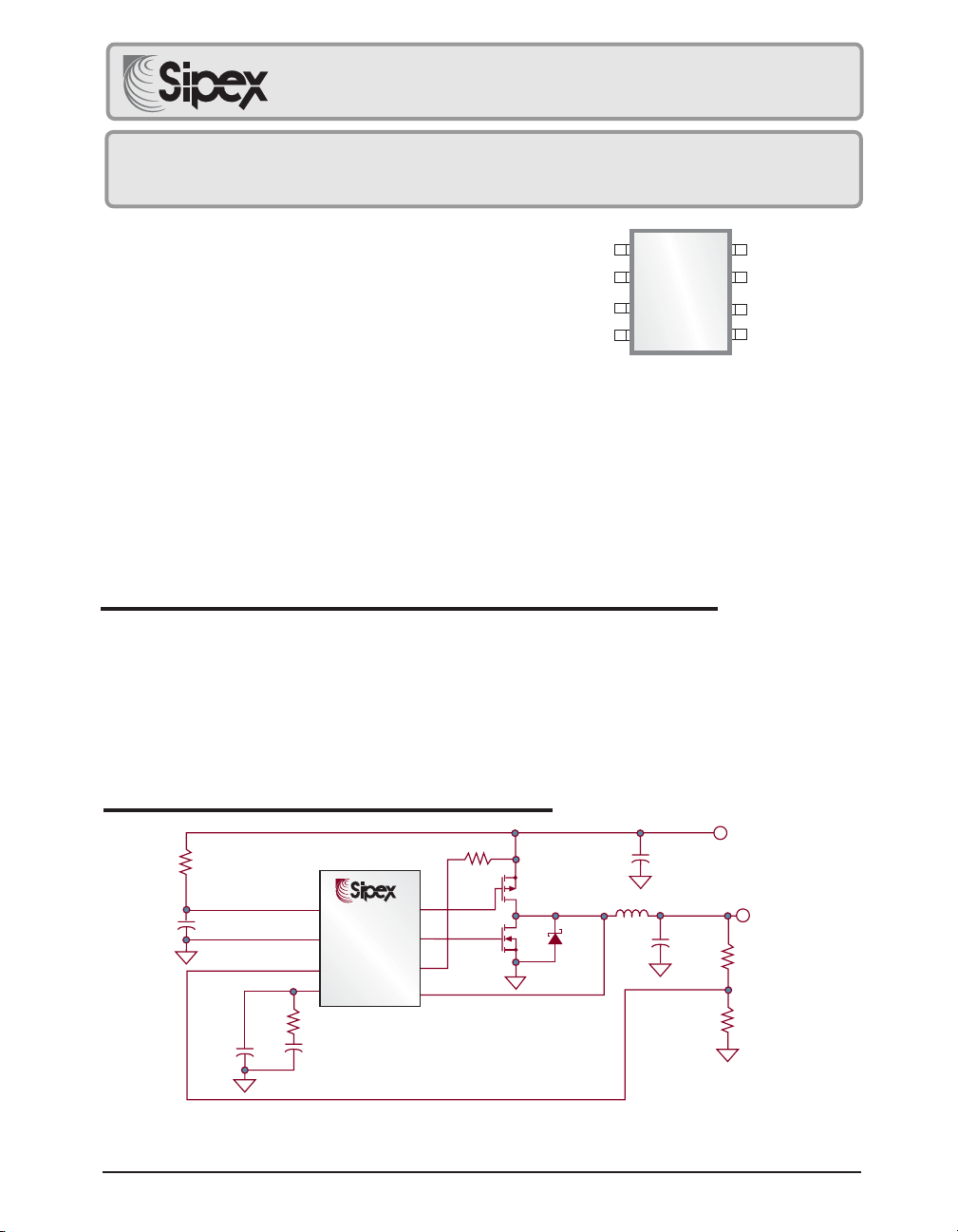
TYPICAL APPLICATION CIRCUIT
RSET
2.3k
Q1
Q2
DS
1.8µH
L1
C
IN
47µF
Ceramic 6.3V
C
OUT
470µF x 2
DESCRIPTION
3.3V
V
IN
1.9V 8A
V
OUT
R1
5.2k
R2
10k
Q1 = FAIRCHILD FDS6375
Q2 = FAIRCHILD FDS6690A
DS = STMICROELECTRONICS STPS2L25BU
Date: 11/29/04 SP6121 Low Voltage, Synchronous Step Down PWM Controller © Copyright 2004 Sipex Corporation
L1 = PANASONIC ETQ-P6F1R6SFA
= SANYO 4TPB470M
C
OUT
1
Page 2
ABSOLUTE MAXIMUM RATINGS
......................................................................................................
V
CC
All other pins ............................... -0.3V to VCC+0.3V
Peak Output Current < 10µs
PDRV, NDRV....................................................... 2A
Storage Temperature ...................... -65°C to 150°C
Lead Temperature (Soldering, 10 sec) ..........300°C
7V
These are stress ratings only and functional
operation of the device at these ratings or any other
above those indicated in the operation sections of
the specifications below is not implied. Exposure to
absolute maximum rating conditions for extended
periods of time may affect reliability.
ESD Rating ............................................... 2kV HBM
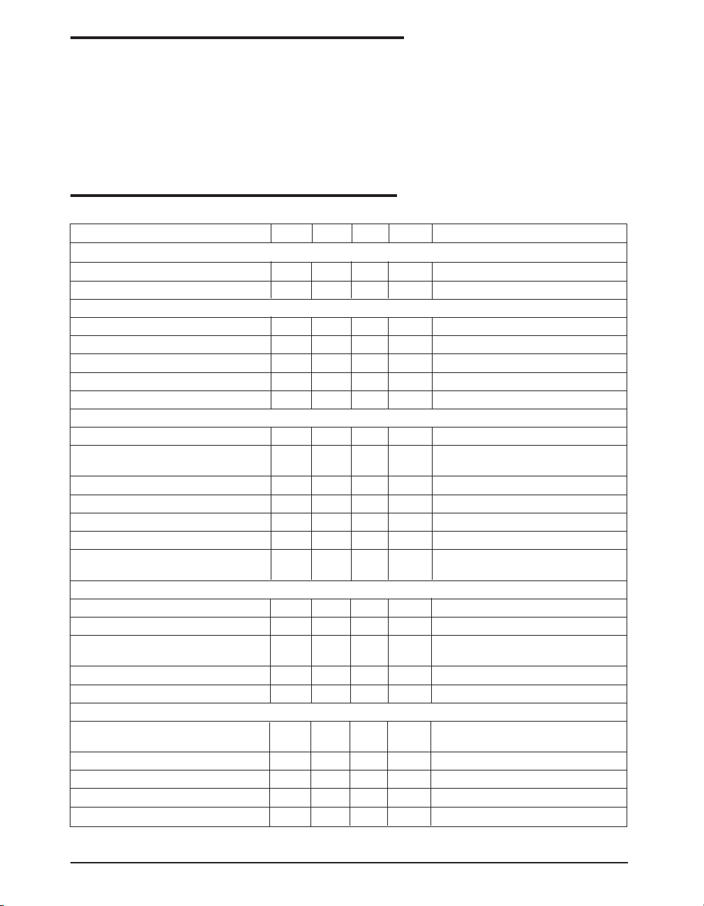
ELECTRICAL CHARACTERISTICS
Unless otherwise specified: 0°C < TA < 70°C, 3.0V < VCC < 5.5V, C
PARAMETER MIN TYP MAX UNITS CONDITIONS
QUIESCENT CURRENT
VCC Supply Current - 0.5 1.0 mA No Switching
VCC Supply Current (Disabled) - 25 60 µA COMP = 0V
ERROR AMPLIFIER
Error Amplifier Transconductance 600 µs
COMP Sink Current 15 35 65 µAV
COMP Source Current 15 35 65 µAVFB =1.15V, COMP=1.8V
COMP Output Impedance 3 MΩ
VFB Input Bias Current 100 nA
ERROR AMPLIFIER REFERENCE
Initial Accuracy 1.238 1.250 1.262 V Trimmed with Error Amp in Unity Gain
Error Amplifier Reference over 1.225 1.250 1.275 V
Line, Load and Temperature
OSCILLATOR & DELAY PATH
Internal Oscillator Frequency 440 500 560 kHz
Maximum Duty Cycle 100 - - % COMP = 2V
Minimum Duty Cycle - - 0 % COMP = 0.8V
Minimum PDRV Pulse Width 100 ns V
CURRENT LIMIT
Internal Current Limit Threshold 125 160 195 mV V
ISET Sink Current 25 30 35 µAV
Current Limit Threshold and 0.33 %/C
ISET Temperature Coefficient
Current Limit Time Constant 15 µs
ISENSE Input Bias Current - - 100 nA
SOFT START, SHUTDOWN, UVLO
Internal Soft Start Slew Rate 0.4 V/ms Measured at COMP pin on the
Internal Soft Start Delay Time 1.5 ms COMP charging to PDRV switching
COMP Discharge Current 150 300 µA COMP = 0.5V, Fault Initiated
COMP Clamp Voltage 0.6 0.7 0.8 V V
COMP Clamp Current 100 µA COMP = 0.5V, VFB =1.15V
COMP
= 22nF, C
PDRV
= C
= 3.3nF, VFB = 1.25V, I
NDRV
= I
SET
= 1.35V, COMP=0.8V, No Faults
FB
> 4.5V, Ramp up COMP voltage
CC
until PDRV starts switching
- V
ISET
ISENSE
=5V, TA = 25°C
ISET
= VCC, GND=0V
SENSE
, TA = 25°C
transition from shutdown
= 1.3V
FB
Date: 11/29/04 SP6121 Low Voltage, Synchronous Step Down PWM Controller © Copyright 2004 Sipex Corporation
2
Page 3
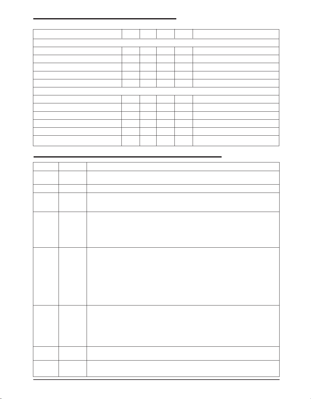
ELECTRICAL CHARACTERISTICS
Unless otherwise specified: 0°C < TA < 70°C, 3.0V < VCC < 5.5V, C
PARAMETER MIN TYP MAX UNITS CONDITIONS
SOFT START, SHUTDOWN, UVLO: continued
Shutdown Threshold Voltage 0.2 0.3 0.4 V Measured at COMP Pin
Shutdown Input Pull-up Current 5 µA COMP = 0.2V, Measured at COMP pin
VCC Start Threshold 2.69 2.79 2.89 V
VCC Stop Threshold 2.59 2.69 2.79 V
VCC Hysteresis - 100 - mV
GATE DRIVERS
PDRV Rise Time - 40 110 ns V
PDRV Fall Time - 40 110 ns V
NDRV Rise Time - 40 110 ns VCC > 4.5V
PDRV Fall Time - 40 110 ns V
PDRV to NDRV Non-Overlap Time 80 ns VCC > 4.5V
NDRV to PDRV Non-Overlap Time 50 ns V
COMP
= 22nF, C
PDRV
= C
= 3.3nF, VFB = 1.25V, I
NDRV
CC
CC
CC
CC
> 4.5V
> 4.5V
> 4.5V
> 4.5V
SET
= I
SENSE
= VCC, GND=0V
PIN DESCRIPTION
PIN NO. PIN NAME DESCRIPTION
1VCCPositive input supply for the control circuitry and gate drivers. Properly bypass this pin
2 GND Ground pin. Both power and control circuitry of the IC is referenced to this pin.
3VFBFeedback Voltage Pin. It is the inverting input of the Error Amplifier and serves as the
4 COMP Output of the Error Amplifier. It is internally connected to the non-inverting input of the
5I
SENSE
6I
7 NDRV High current driver output for the low side MOSFET switch. It is always low if PDRV is
8 PDRV High current driver output for the high side MOSFET switch. It is always high if NDRV
to GND with a low ESL/ESR ceramic capacitor.
output voltage feedback point for the buck converter. The output voltage is sensed and
can be adjusted through an external resistor divider.
PWM comparator. A lead-lag network is typically connected to the COMP pin to
compensate the feedback loop in order to optimize the dynamic performance of the
voltage mode control loop. Sleep mode can be invoked by pulling the COMP pin below
0.2V with an external open-drain or open-collector transistor. Supply current is reduced
to 25µA (typical) in shutdown. An internal 5µA pull-up ensures start-up.
Current Limit Sense pin. Connect this pin to the switching node at the junction between
the two external power MOSFET transistors. This pin monitors the voltage dropped
across the R
this drop exceeds the sum of the voltage programmed through the I
internal 160mV threshold, the overcurrent comparator sets the fault latch and termi-
of the high side P-channel MOSFET while it is conducting. When
DS(ON)
SET
nates the output pulses. The controller stops switching and goes through a hiccup
sequence. This prevents excessive power dissipation in the external power MOSFETs
during an overload condition. An internal delay circuit prevents that very short and mild
overload conditions, that could occur during a load transient, activate the current limit
circuit.
Current Limit Threshold pin. An external resistor connected between this pin and the
SET
source of the high side P-channel MOSFET adds to the internal current limit threshold
of 160mV. If a current limit threshold in excess of 160mV is required, the external
programming resistor can properly be chosen based on the internal 30µA pull down
current available on the I
current limit threshold have a positive temperature coefficient to provide first order
pin. Both this 30µA current source and the 160mV built-in
SET
correction for the temperature coefficient of the external P-channel MOSFET’s R
low or during a fault.
is high or during a fault.
pin plus the
DS(ON)
.
Date: 11/29/04 SP6121 Low Voltage, Synchronous Step Down PWM Controller © Copyright 2004 Sipex Corporation
3
Page 4
FAULT
SOFTSTART
V
3
FB
COMP
4
V
1
CC
ISET
6
30µA
(3300 ppm/°C)
ISENSE
5
Reference
0.4V/ms
2.79V ON
2.69V OFF
1.25V
+
-
PDRV
X 3.3
GM
ERROR
AMP
+
-
UVLO
-
+
530mV
(3300 ppm/°C)
5µA
750mV RAMP
Over Current
(Gated S&H)
+
-
1V
300mV
PWM COMP
-
+
-
+
-
+
SHUTDOWN
DRIVER ENABLE
SHUTDOWN
RESET
Dominant
S
Q
R
F = 500kHz
Reset
Dominant
S
R
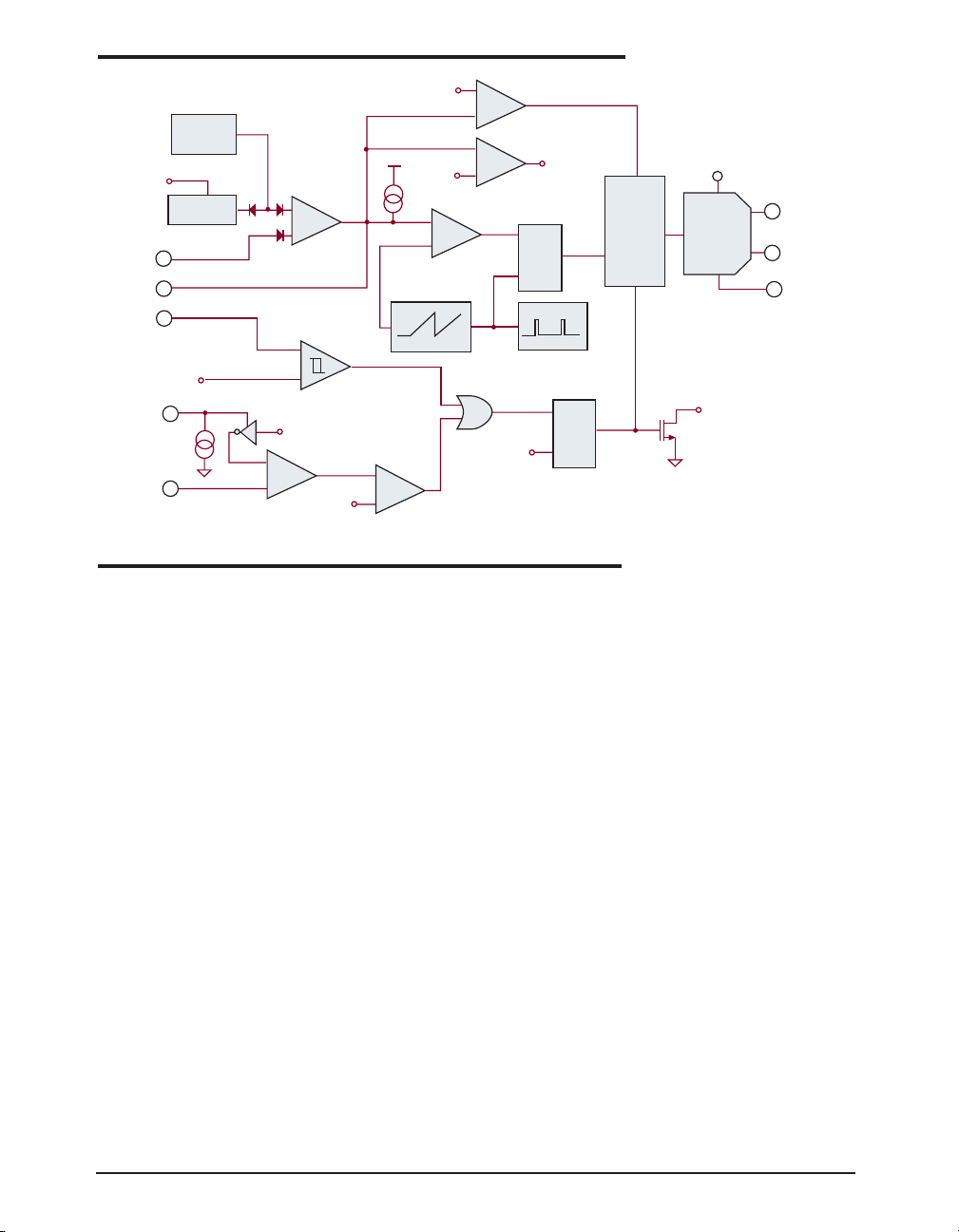
FUNCTIONAL DIAGRAM
V
CC
PWM
Logic
FAULT
Q
Synchronous
Driver
COMP
THEORY OF OPERATION
8
PDRV
7
NDRV
2
GND
General Overview
The SP6121 is a constant frequency, voltage
mode, synchronous PWM controller designed
for low voltage, DC/DC step down converters.
It is intended to provide complete control for a
high power, high efficiency, precisely regulated
output voltage from a highly integrated 8-pin
solution.
The internal free-running oscillator accurately
sets the PWM frequency at 500kHz without
requiring any external elements and allows the
use of physically small, low value external components without compromising performance. A
transconductance amplifier is used for the error
amplifier, which compares an attenuated sample
of the output voltage with a precision reference
voltage. The output of the error amplifier
(COMP), is compared to a 0.75V peak-to-peak
ramp waveform to provide PWM control. The
COMP pin provides access to the output of the
error amplifier and allows the use of external
components to stabilize the voltage loop.
High efficiency is obtained through the use of
synchronous rectification. Synchronous regulators replace the catch diode in the standard buck
converter with a low R
Date: 11/29/04 SP6121 Low Voltage, Synchronous Step Down PWM Controller © Copyright 2004 Sipex Corporation
DS(ON)
N-channel
MOSFET switch allowing for significant efficiency improvements. The SP6121 includes two
fast MOSFET drivers with internal non-overlap
circuitry and drives a complementary pair of
power transistors, P-channel on the high side,
and N-channel on the low side. The use of a Pchannel high side device minimizes complexity
and external component count by eliminating
the need for a charge pump that would otherwise
be required to fully enhance an N-channel device. It also allows inherent 100% duty cycle for
low dropout operation in the event of a low input
supply voltage condition.
The SP6121 includes an internal 0.4V/ms softstart circuit that provides controlled ramp up of
the output voltage, preventing overshoot and
inrush current at power up.
Current limiting is implemented by monitoring
the voltage drop across the R
DS(ON)
of the high
side P-channel MOSFET while it is conducting,
thereby eliminating the need for an external
sense resistor. The over-current comparator has
a built-in threshold of 160mV that can be programmed to higher values using a single external resistor, connected to the I
pin, whose
SET
4
Page 5

THEORY OF OPERATION
value is selected to match the MOSFET characteristics. When the over-current threshold is
exceeded, the over-current comparator sets the
fault latch and terminates the output pulses. The
controller stops switching and goes through a
hiccup sequence. This prevents excessive power
dissipation in the external power MOSFETs
during an overload condition. An internal delay
circuit prevents that very short and mild overload conditions, that could occur during a load
transient, activate the current limit circuit.
A low power sleep mode can be invoked in the
SP6121 by externally forcing the COMP pin
below 0.3V. Quiescent supply current in sleep
mode is typically less than 25µA. An internal
5µA pull-up current at the COMP pin brings the
SP6121 out of shutdown mode.
The SP6121 also includes under-voltage lockout and over-voltage protection. Output overvoltage protection is achieved by turning off the
high side switch, and turning on the low side Nchannel MOSFET full time.
Enable
Low quiescent mode or “Sleep Mode” is initiated by pulling the COMP pin below 0.3V with
an external open-drain or open-collector transistor. Supply current is reduced to 25µA (typical) in shutdown. On power-up, assuming that
VCC has exceeded the UVLO start threshold
(2.79V), an internal 5µA pull-up current at the
COMP pin brings the SP6121 out of shutdown
mode and ensures start-up. During normal operating conditions and in absence of a fault, an
internal clamp prevents the COMP pin from
swinging below 0.6V. This guarantees that during mild transient conditions, due either to line
or load variations, the SP6121 does not enter
shutdown unless it is externally activated.
During Sleep Mode, the high side and low side
MOSFETs are turned off and the internal soft
If no faults are present, the SP6121 will initiate
a soft start when VCC exceeds 2.79V.
Hysteresis (about 100mV) in the UVLO comparator provides noise immunity at start-up.
Soft Start
Soft start is required on step-down controllers to
prevent excess inrush current through the power
train during start-up. Typically this is managed
by sourcing a controlled current into a timing
capacitor and then using the voltage across this
capacitor to slowly ramp up either the error amp
reference or the error amp output (COMP). The
control loop creates narrow width driver pulses
while the output voltage is low and allows these
pulses to increase to their steady-state duty
cycle as the output voltage increases to its regulated value. As a result of controlling the inductor volt*second product during startup, inrush
current is also controlled.
In the SP6121 the duration of the soft-start is
controlled by an internal timing circuit that
provides a 0.4V/ms slew-rate, which is used
during start-up and over-current to set the hiccup time. The SP6121 implements soft-start by
ramping up the error amplifier reference voltage
providing a controlled slew-rate of the output
voltage, thereby preventing overshoot and inrush current at power up.
The presence of the output capacitor creates
extra current draw during startup. Simply stated,
dV
/dt requires an average sustained current
OUT
in the output capacitor and this current must be
considered while calculating peak inrush current and over current thresholds. An approximate expression to determine the excess inrush
current due to the dV
tor C
OUT
IC
OUT
is:
= C
OUT
/dt of the output capaci-
OUT
*(0.4 V/ms) *
V
1.25
OUT
start voltage is held low.
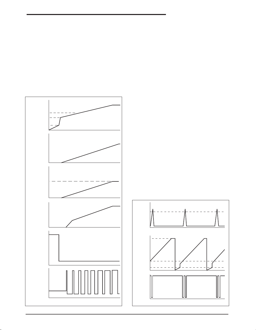
As Figure 1 shows, the SS voltage controls a
UVLO
Assuming that there is not shutdown condition
present, then the voltage on the VCC pin determines operation of the SP6121. As VCC rises,
the UVLO block monitors VCC and keeps the
high side and low side MOSFETS off and the
internal SS voltage low until VCC reaches 2.79V.
Date: 11/29/04 SP6121 Low Voltage, Synchronous Step Down PWM Controller © Copyright 2004 Sipex Corporation
variety of signals. First, provided all the external fault conditions are removed, an internal
5µA pull-up at the COMP pin brings the SP6121
out of shutdown mode. The internal timing
circuit is then activated and controls the rampup of the error amp reference voltage. The
COMP pin is pulled to 0.7V by the internal
5
Page 6
THEORY OF OPERATION
clamp and then gradually charges preventing
the error amplifier from forcing the loop to
maximum duty cycle. As the COMP voltage
crosses about 1V (valley voltage of the PWM
ramp), the driver begins to switch the high side
MOSFET with narrow pulses in an effort to
keep the converter output regulated . The SP6121
operates at low duty cycle as the COMP voltage
increases above 1V. As the error amp reference
ramps upward, the driver pulses widen until a
steady state value is reached and the output
voltage is regulated to the final value ending the
soft start charge cycle.
COMP
1 V
0.7 V
0.3 V
0 V
Internal SS
Voltage
Error Amp
Reference
Voltage
1.25V
0 V
I(L)
Inductor
Current
0 A
V(V
CC
FAULT
dVss/dt = 0.4V/ms
V
OUT
)
= V
* (1+R1/R2)
(REF)
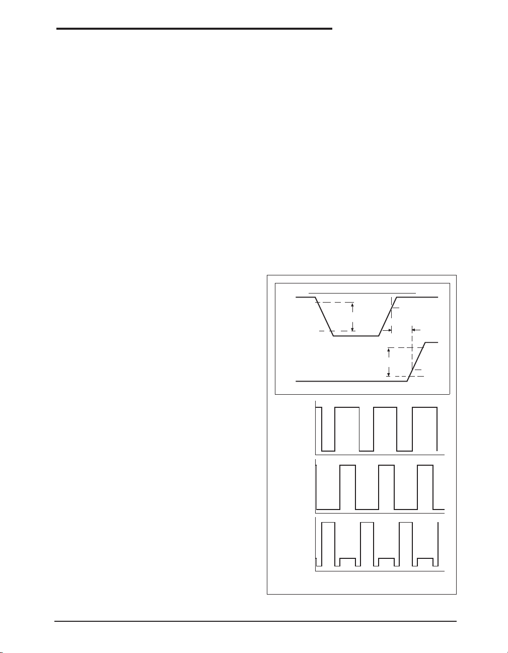
Hiccup Mode
When the converter enters a fault mode, the
SP6121 holds the high side and low side
MOSFETs off for a finite period of time. Provided that the SP6121 is enabled, this time is set
by the internal charge of the SS capacitor. In the
event of an over-current condition, the current
sense comparator sets the fault latch, which in
turn discharge the internal SS capacitor, the
COMP pin and holds the output drivers off.
During this condition, the SP6121 stays off for
the time it takes to discharge the COMP pin
down below the 0.3V shutdown threshold. As
soon as the COMP pin reaches 0.3V, the fault
latch is reset and the SP6121 is allowed to
attempt restart just like during a normal soft start
cycle. The COMP pin has to charge back to 1V
before any output switching can take place. At
this point, the regulator attempts to restart normally by delivering short gate pulses to the
output switches. If the over-current condition
persists, the regulator will be kept off for the
total time that it takes to charge the internal softstart capacitor to within 1V from the input
supply voltage VCC plus the time required by the
COMP voltage to cross the 1V threshold. This
total time is typically several milli-seconds and
minimizes thermal stress to the regulator components as the over-current condition persists.
The waveforms that describe the hiccup mode
operation are shown in Figure 2.
V
(ISET)-V(ISENSE)
160 mV
0 V
COMP
Vol tage
3 V
0 V
V(VCC)
SWN
Voltage
0 V
TIME
Figure 1. SP6121 Soft Start Waveforms
Date: 11/29/04 SP6121 Low Voltage, Synchronous Step Down PWM Controller © Copyright 2004 Sipex Corporation
1.0 V
0.3 V
0 V
V
(VCC)
PDRV
Vol tage
0V
TIME
Figure 2. SP6121 Hiccup mode waveforms
6
Page 7
THEORY OF OPERATION
Over Current Protection
Over current protection on the SP6121 is implemented through detection of an excess voltage
condition across the high side PMOS switch
during conduction. This is typically referred to
as high side R
detection and eliminates the
DS(ON)
need of an external sense resistor. The over
current comparator charges an internal sampling capacitor each time V
(ISET)
- V
(ISENSE)
exceeds the 160mV (typ) internal threshold and
the PDRV voltage is low. The discharge/charge
current ratio on the sampling capacitor is about
2%. Therefore, provided that the over current
condition persists, the capacitor voltage will be
pumped up during each time PDRV switches
low. This voltage will trigger an over current
condition upon reaching a CMOS inverter threshold. There are many advantages to this approach. First, the filtering action of the gated S/
H scheme protects against false and undesirable
triggering that could occur during a minor transient overload condition or supply line noise.
Furthermore, the total amount of time to trigger
the fault depends on the on-time of the PMOS
switch. Ten, 1µs pulses are equivalent to twenty,
500ns pulses or one, 10µs pulse, however, depending on the period, each scenario takes a
different amount of total time to trigger a fault.
Therefore, the fault becomes an indicator of
average power in the PMOS switch.
Although the 160 mV internal threshold is fixed,
the overall R
increased by placing a resistor from I
detection voltage can be
DS(ON)
SET
to the
source of the PMOS. A 30µA sink current programs the additional voltage.
In order for the current limit circuit to operate
properly and accurately, the I
SET
and I
SENSE
pins
must be Kelvin connected to the high side
PMOS’s source and drain pins.
The 160mV threshold and 30µA I
SET
current
have 3300 ppm/°C temperature coefficients in
an effort to first order match the thermal characteristics of the R
of the PMOS switch. It
DS(ON)
assumed that the SP6121 will be used in compact designs where there is a high amount of
thermal coupling between the PMOS and the
controller.
Output Drivers
The SP6121, unlike some other bipolar controller IC’s, incorporates gate drivers with rail-torail swing that help prevent spurious turn on due
to capacitive coupling. The driver stage consists
of one high side PMOS, 4Ω driver, PDRV, and
one low side, 4Ω, NFET driver, NDRV, optimized for driving external power MOSFET’s in
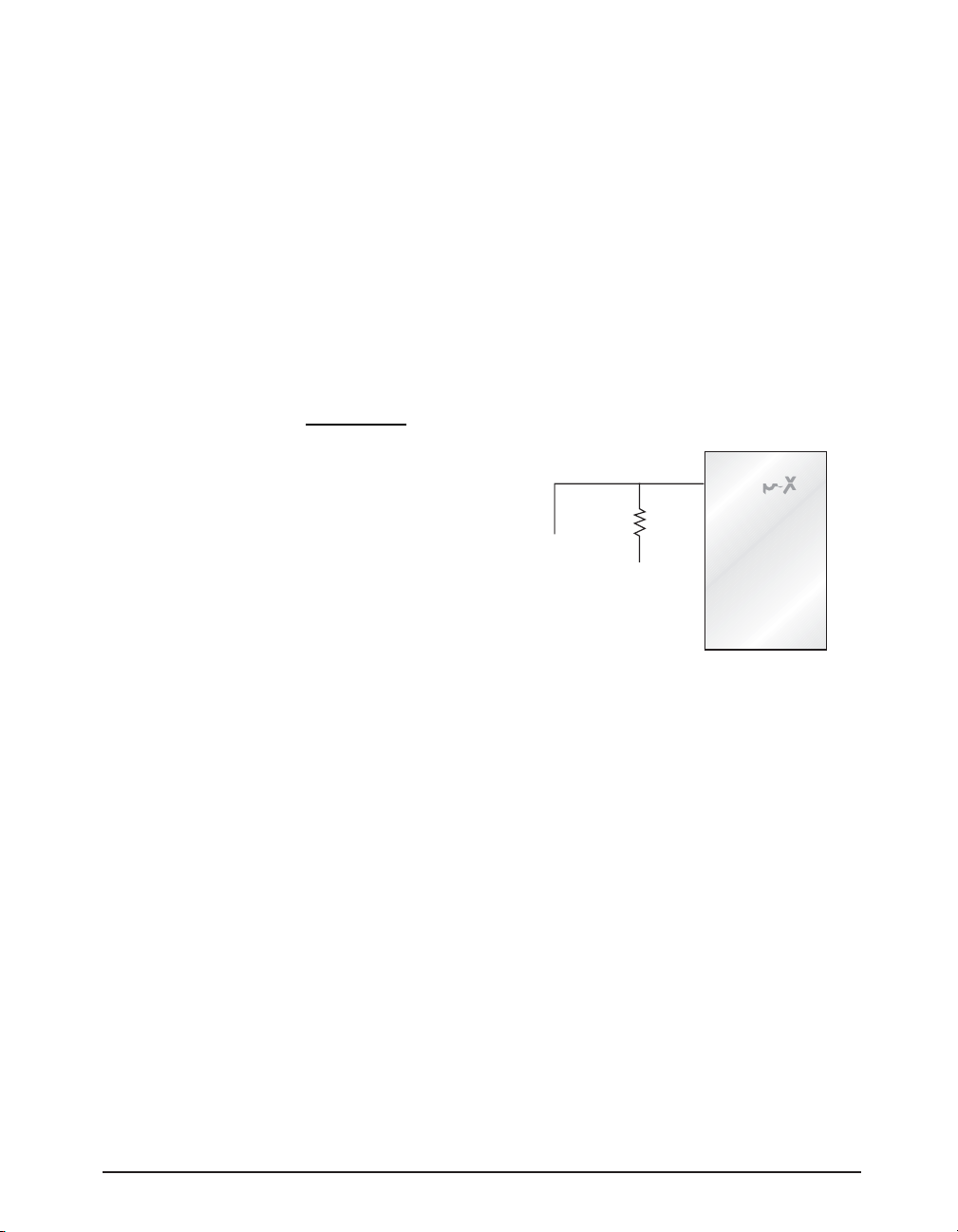
a synchronous buck topology. The output drivers also provide gate drive non-overlap mechanism that provides a dead time between PDRV
and NDRV transitions to avoid potential shootthrough problems in the external MOSFET’s.
Figure 3 shows typical waveforms for the output
drivers. As with all synchronous designs, care
must be taken to ensure that the MOSFETs are
properly chosen for non-overlap time, enhancement gate drive voltage, “on” resistance R
DS(ON)
reverse transfer capacitance Crss, input voltage
and maximum output current.
GATE DRIVER TEST CONDITIONS
5 V
90 %
PDRV(NDRV)
10 %
5 V
NDRV(PDRV)
V(V
CC
PDRV
Voltage
0 V
CC
V(V
NDRV
Voltage
0 V
V(V
CC=VIN
SWN
Voltage
~ 0 V
- V(Diode) V
FALL TIME
RISE TIME
)
)
)
TIME
Vcc-2 V
NON-OVERLAP
90 %
2 V
10 %
,
Figure 3. SP6121 Output Driver Waveforms.
Date: 11/29/04 SP6121 Low Voltage, Synchronous Step Down PWM Controller © Copyright 2004 Sipex Corporation
7
Page 8

Inductor Selection
There are many factors to consider in selecting
the inductor including cost, efficiency, size and
EMI. In a typical SP6121 circuit, the inductor is
chosen primarily for value, saturation current
and DC resistance. Increasing the inductor value
will decrease output voltage ripple, but degrade
transient response. Low inductor values provide
the smallest size, but cause large ripple currents,
poor efficiency and more output capacitance to
smooth out the larger ripple current. The inductor must also be able to handle the peak current
at the switching frequency without saturating,
and the copper resistance in the winding should
be kept as low as possible to minimize resistive
power loss. A good compromise between size,
loss and cost is to set the inductor ripple current
to be within 20% to 40% of the maximum output
current.
The switching frequency and the inductor operating point determine the inductor value as follows:
L
=
(max)
OUTINOUT
IKFV
(max)(max)
OUTrSIN
)(
VVV
−
where;
FS = switching frequency
Kr = ratio of the peak to peak inductor ripple
current to the maximum output current
The peak to peak inductor ripple current is:
APPLICATION INFORMATION
duce considerable ac core loss, especially when
the inductor value is relatively low and the
ripple current is high. Ferrite materials, on the
other hand, are more expensive and have an
abrupt saturation characteristic with the inductance dropping sharply when the peak design
current is exceeded. Nevertheless, they are preferred at high switching frequencies because
they present very low core loss and the design
only needs to prevent saturation.
The power dissipated in the inductor is equal to
the sum of the core and copper losses. To minimize copper losses, the winding resistance needs
to be minimized, but this usually comes at the
expense of a larger inductor. Core losses have a
more significant contribution at low output current where the copper losses are at a minimum,
and can typically be neglected at higher output
currents where the copper losses dominate. Core
loss information is usually available from the
magnetic vendor.
The copper loss in the inductor can be calculated
using the following equation:
2
RIP
)()(
WINDINGRMSLCuL
where I
=
is the RMS inductor current that
L(RMS)
can be calculated as follows:
I
L(RMS)
= I
OUT(max)
1 +
1 ( IPP
I
3
) 2
OUT(max)
)( −
VVV
=
I
PP
(max)
(max)
OUTINOUT
LFV
SIN
Once the required inductor value is selected, the
proper selection of core material is based on
peak inductor current and efficiency requirements. The core material must be large enough
not to saturate at the peak inductor current
Output Capacitor Selection
The required ESR (Equivalent Series Resistance) and capacitance drive the selection of the
type and quantity of the output capacitors. The
ESR must be small enough that both the resistive voltage deviation due to a step change in the
load current and the output ripple voltage do not
exceed the tolerance limits expected on the
output voltage. During an output load transient,
I
II +=
(max)
OUTPEAK
PP
2
and provide low core loss at the high switching
frequency. Low cost powdered iron cores have
the output capacitor must supply all the additional current demanded by the load until the
SP6121 adjusts the inductor current to the new
value. Therefore the capacitance must be large
enough so that the output voltage is held up
a gradual saturation characteristic but can intro-
Date: 11/29/04 SP6121 Low Voltage, Synchronous Step Down PWM Controller © Copyright 2004 Sipex Corporation
8
Page 9

while the inductor current ramps up or down to
the value corresponding to the new load current.
Additionally, the ESR in the output capacitor
causes a step in the output voltage equal to the
ESR value multiplied by the change in load
current. Because of the fast transient response
provided by the SP6121 when exposed to output
load transient, the output capacitor is typically
chosen for ESR , not for capacitance value.
The output capacitor’s ESR, combined with the
inductor ripple current, is typically the main
contributor to output voltage ripple. The maximum allowable ESR required to maintain a
specified output voltage ripple can be calculated
by:
V
∆
R
ESR
OUT
≤
I
PP
where;
∆V
= peak to peak output voltage ripple
OUT
IPP = peak to peak inductor ripple current
The total output ripple is a combination of the
ESR and the output capacitance value and can
be calculated as follows:
V
OUT
(IPP (1 – D)
=
C
OUTFS
∆
)
2
+ (IPPR
ESR
2
)
where;
D = duty cycle equal to V
C
= output capacitance value
OUT
OUT/VIN
Recommended capacitors that can be used effectively in SP6121 applications are: low-ESR
aluminum electrolytic capacitors, OS-CON capacitors that provide a very high performance/
size ratio for electrolytic capacitors and lowESR tantalum capacitors. AVX TPS series and
Kemet T510 surface mount capacitors are popular tantalum capacitors that work well in SP6121
applications. POSCAP from Sanyo is a solid
electrolytic chip capacitor that has low ESR and
high capacitance. For the same ESR value,
POSCAP has lower profile compared with tantalum capacitor.
APPLICATIONS INFORMATION
Panasonic offers the SP series of specialty polymer aluminum electrolytic surface mount capacitors. These capacitors have a lower ESR
than tantalum capacitors, reducing the total number of capacitance required for a given transient
response.
Input Capacitor Selection
The input capacitor should be selected for ripple
current rating, capacitance and voltage rating.
The input capacitor must meet the ripple current
requirement imposed by the switching current.
In continuous conduction mode, the source current of the high-side MOSFET is approximately
a square wave of duty cycle V
/ VIN. Most of
OUT
this current is supplied by the input bypass
capacitors. The RMS value of input capacitor
current is determined at the maximum output
current and under the assumption that the peak
to peak inductor ripple current is low, it is given
by:
I
CIN(rms)
= I
OUT(max)
√
D(1 - D)
The worse case occurs when the duty cycle D is
50% and gives an RMS current value equal to
IOUT/2. Select input capacitors with adequate
ripple current rating to ensure reliable operation.
The power dissipated in the input capacitor is:
2
RIP =
)( CINESRrmsCINCIN
)(
This can become a significant part of power
losses in a converter and reduce the overall
energy transfer efficiency.
The input voltage ripple primarily depends on
the input capacitor ESR and capacitance. Ignoring the inductor ripple current, the input voltage
ripple can be determined by:
∆
VIN = I
OUT(MAX)RESR(CIN)
I
OUT(MAX)VOUT(VIN
+
FSCINV
- V
OUT
2
IN
The capacitor type suitable for the output capacitors can also be used for the input capacitors. However, exercise extra caution when tantalum capacitors are considered. Tantalum capacitors are known for catastrophic failure when
exposed to surge current, and input capacitors
are prone to such surge current when power
)
Date: 11/29/04 SP6121 Low Voltage, Synchronous Step Down PWM Controller © Copyright 2004 Sipex Corporation
9
Page 10

supplies are connected ‘live’ to low impedance
power sources. Certain tantalum capacitors, such
as AVX TPS series, are surge tested. For generic tantalum capacitors, use 2:1 voltage derating to protect the input capacitors from surge
fall-out.
MOSFET Selection
The SP6121 drives a PMOS MOSFET on the
high side and an NMOS MOSFET synchronous
rectifier on the low side. Using a PMOS switch
on the high side negates the need for an external
charge pump and simplifies the application circuit.
The losses associated with MOSFETs can be
divided into conduction and switching losses.
Conduction losses are related to the on resistance of MOSFETs, and increase with the load
current. Switching losses occur on each on/off
transition when the MOSFETs experience both
high current and voltage. Since the bottom
MOSFET switches current from/to a paralleled
diode (either its own body diode or a Schottky
diode), the voltage across the MOSFET is no
more than 1V during switching transition. As a
result, its switching losses are negligible. The
switching losses are difficult to quantify due to
all the variables affecting turn on/off time. However, making the assumption that the turn on and
turn off transition times are equal, the transition
time can be approximated by:
tT =
C
ISSVIN
I
G
,
where;
C
is the PMOS’s input capacitance, or the
ISS
sum of the gate-to-source capacitance, CGS, and
the drain-to-gate capacitance, CGD. This parameter can be directly obtained from the MOSFET’s
data sheet IG is the gate drive current provided
by the SP6121 (approximately 1A at VIN=5V)
and VIN is the input supply voltage.
Therefore an approximate expression for the
switching losses associated with the high side
MOSFET can be given as:
P
SH(max)
= (V
IN(max)
+ VF)I
OUT(max)tTFS
,
where;
tT = the switching transition time
VF = free wheeling diode drop
APPLICATIONS INFORMATION
Switching losses need to be taken into account
for high switching frequency, since they are
directly proportional to switching frequency.
The conduction losses associated with top and
bottom MOSFETs are determined by
P
P
CL(max)
CH(max)
= R
= R
DS(ON)IOUT(max)
DS(ON)IOUT(max)
2
D
2
(1 - D),
where;
P
= conduction losses of the high side
CH(max)
MOSFET
P
= conduction losses of the low side
CL(max)
MOSFET
R
= drain to source on resistance.
DS(ON)
The total power losses of the top MOSFET are
the sum of switching and conduction losses. For
synchronous buck converters of efficiency over
90%, allow no more than 4% power losses for
high or low side MOSFETs. For input voltages
of 3.3V and 5V, conduction losses often dominate switching losses. Therefore, lowering the
R
of the MOSFETs always improves
DS(ON)
efficiency even though it gives rise to higher
switching losses due to increased C
ISS
.
Total gate charge is the charge required to turn
the MOSFETs on and off under the specified
operating conditions (VGS and VDS). The gate
charge is provided by the SP6121 gate drive
circuitry. (At 500kHz switching frequency, the
gate charge is the dominant source of power
dissipation in the SP6121.) At low output levels,
this power dissipation is noticeable as a reduction in efficiency. The average current required
to drive the high side and low side MOSFETs is:
I
= QGHFS + QGLFS,
G(av)
where;
QGH = gate charge of PMOS
QGL = gate charge of NMOS
Considering that the gate charge current comes
from the input supply voltage VIN, the power
dissipated in the SP6121 due to the gate drive is:
P
GATE DRIVE
R
varies greatly with the gate driver volt-
DS(ON)
age. The MOSFET vendors often specify R
= VINI
G(av)
DS(ON)
on multiple gate to source voltages (VGS), as
Date: 11/29/04 SP6121 Low Voltage, Synchronous Step Down PWM Controller © Copyright 2004 Sipex Corporation
10
Page 11
well as provide typical curve of R
V
. For 5V input, use the R
GS
4.5V V
. At the time of this publication, ven-
GS
DS(ON)
versus
DS(ON)
specified at
dors, such as Fairchild, Siliconix and International Rectifier, have started to specify R
DS(ON)
at VGS less than 3V. This has provided necessary
data for designs in which these MOSFETs are
driven with 3.3V and made it possible to use
SP6121 in 3.3V only applications.
Thermal calculation must be conducted to ensure the MOSFET can handle the maximum
load current. The junction temperature of the
MOSFET, determined as follows, must stay
below the maximum rating.
TT
+=
(max)(max)
AJ
P
MOSFET
R
θ
JA
(max)
,
where;
T
= maximum ambient temperature
A(max)
P
MOSFET(max)
= maximum power dissipation of
the MOSFET
R
= junction to ambient thermal resistance.
θJA
R
of the device depends greatly on the board
θJA
layout, as well as device package. Significant
thermal improvement can be achieved in the
maximum power dissipation through the proper
design of copper mounting pads on the circuit
board. For example, in a SO-8 package, placing two 0.04 square inches copper pad directly under the package, without occupying
additional board space, can increase the maximum power from approximately 1 to 1.2W.
For DPAK package, enlarging the tap mounting pad to 1 square inches reduces the R
θJA
from 96°C/W to 40°C/W.
Schottky diode alleviates this noise and additionally improves efficiency thanks to its low
forward voltage. The reverse voltage across the
diode is equal to input voltage, and the diode
must be able to handle the peak current equal to
the maximum load current.
The power dissipation of the Schottky diode is
determined by
P
DIODE
= 2VFI
OUTTNOLFS
where;
T
= non-overlap time between PDRV and
NOL
NDRV.
VF = forward voltage of the Schottky diode.
®
SP6121
Schottky Diode Selection
When paralleled with the bottom MOSFET, an
optional Schottky diode can improve efficiency
and reduce noise. Without this Schottky diode,
the body diode of the bottom MOSFET conducts the current during the non-overlap time
when both MOSFETs are turned off. Unfortunately, the body diode has high forward voltage
and reverse recovery problem. The reverse recovery of the body diode causes additional
switching noises when the diode turns off. The
Date: 11/29/04 SP6121 Low Voltage, Synchronous Step Down PWM Controller © Copyright 2004 Sipex Corporation
11
Page 12
f
APPLICATIONS INFORMATION
associated with the output capacitors and can be
determined by
=
1
OUTRESR
f
Z(ESR)
2πC
Crossover frequency of 20kHz is a sound first
try if low ESR tantalum capacitors or poscaps
are used at the output. The next step is to calculate the complex conjugate poles contributed by
the LC output filter,
1
f
=
P(LC)
2π√ LC
OUT
The open loop gain of the whole system can be
divided into the gain of the error amplifier,
PWM modulator, buck converter, and feedback
resistor divider. In order to crossover at the
selected frequency fco, the gain of the error
amplifier has to compensate for the attenuation
caused by the rest of the loop at this frequency.
In the RC network shown in Figure 4, the product
of R1 and the error amplifier transconductance
determines this gain. Therefore, R1 can be determined from the following equation that takes
into account the typical error amplifier
transconductance, reference voltage and PWM
ramp built into the SP6121.
975V
R1 =
OUT fCO fZ(ESR)
V
IN fP(LC)
2
In Figure 4, R1 and C1 provides a zero fZ1 which
needs to be placed at or below f
made equal to f
for convenience, the value
P(LC)
P(LC)
. If fZ1 is
of C1 can be calculated as
2πf
1
P(LC)R1
with R1 to
P1
C1 =
The optional C2 generates a pole f
cut down high frequency noise for reliable operation. This pole should be placed one decade
higher than the crossover frequency to avoid
erosion of phase margin. Therefore, the value of
the C2 can be derived from
C2 =
1
20πfCOR
1
Figure 5 illustrates the overall loop frequency
response and frequency of each pole and zero.
To fine-tune the compensation, it is necessary to
physically measure the frequency response using a network analyzer.
Gain
-20db/dec
-40db/dec
Loop
-20db/dec
Error Amplifier
Figure 5. Frequency response of a stable system and its
error amplifier.
-20db/dec
f
-20db/dec
Overcurrent Protection
Over current protection on the SP6121 is implemented through detection of an excess voltage
condition across the high side PMOS switch
during conduction. This is typically referred to
as high side R
R
of Q1 to measure the output current, the
DS(ON)
detection. By using the
DS(ON)
current limit circuit eliminates the sense resistor
that would otherwise be required and the corresponding loss associated with it. This improves
the overall efficiency and reduces the number of
components in the power path benefiting size
and cost. R
sensing is by default inaccu-
DS(ON)
rate and is primarily meant to protect the power
supply during a fault condition. The overcurrent
trip point will vary from unit to unit as the
R
built-in 160mV threshold between the I
I
of Q1 varies. The SP6121 provides a
DS(ON)
pins. If a current limit threshold in excess
SENSE
SET
and
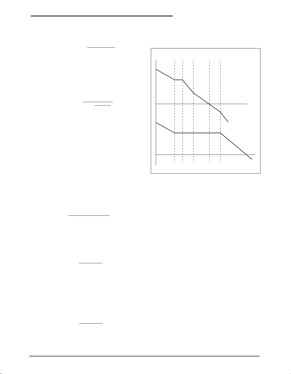
of 160mV is required, an external programming
resistor, R
can be added between I
SET
SET
pin and
VIN as shown in Figure 6.
Date: 11/29/04 SP6121 Low Voltage, Synchronous Step Down PWM Controller © Copyright 2004 Sipex Corporation
12
Page 13
V
OUT
C
IN
SET
IN
V
OUT
pin
SP6121
160mV
-
+
+
30µA
-
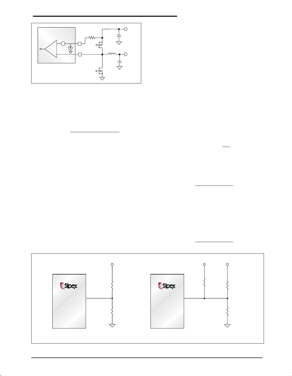
Figure 6. Current Limit Setting
The value of R
can be properly chosen based on
SET
the desired current limit point I
I
I
SENSE
RSET
SET
PDRV
NDRV
Q1
L1
C
Q2
and the internal
MAX
30µA pull down current available on the I
according to the following expression:
I
SET
MAXRDS(ON)
=
R
- 160mV
I
SET
where,
I
= 30µA (typ) sink current from the I
SET
SET
pin.
Kelvin-Sense connections should be made directly at the drain and source of Q1.
The R
sensing scheme implemented in the
DS(ON)
SP6121 provides two additional features that
enhance the performance of the overcurrent
function. First, an internal sample and hold filter
connected after the main current-sense comparator, prevents that noise spikes or very short
and mild overload conditions, that could occur
during a load transient, spuriously activate the
current limit circuitry. This typically eliminates
the need of using any external filtering that would
be otherwise required. Additionally, since the
R
has a positive temperature coefficient,
DS(ON)
APPLICATIONS INFORMATION
both the 30µA sink current present at the I
SET
pin
and the 160mV built-in current limit threshold
have been designed with a positive temperature
coefficient of about 0.33%/C to provide first order
correction for current limit versus temperature.
This compensation relies on the high amount of
thermal coupling that typically exists between the
high side switch Q1 and the SP6121 due to the
compact size of the power supply. With this first
order compensation, the current limit trip point
does not need to be set to an increased level at room
temperature to guarantee a desired output current
level at higher temperatures.
Output Voltage Program
As shown in Figure 7(A), the voltage divider
connecting to the VFB pin programs the output
voltage according to
V
= 1.25(1 +
OUT
R1
R2
)
where 1.25V is the internal reference voltage.
Select R2 in the range of 10k to 100k, and R1 can
be calculated using
R1 =
R2(V
OUT
1.25
- 1.25)
For output voltage less than 1.25V, a simple
circuit shown in Figure 7(B) can be used in
which V
is an external voltage reference
REF
greater than 1.25V. For simplicity, use the same
resistor value for R1 and R2, then R3 is determined as follows,
(V
- 1.25)R1
R3 =
REF
2.5V - V
OUT
V
SP6121
> 1.25V
OUT
SP6121
®
®
V
FB
®
®
V
FB
R1
R2
V
V
REF
R3
OUT
< 1.25V
R1
R2
AB
Figure 7(A) A voltage divider connected to the VFB pin programs the output voltage. (B) A simple circuit using one
external voltage reference programs the output voltages less than 1.25V.
Date: 11/29/04 SP6121 Low Voltage, Synchronous Step Down PWM Controller © Copyright 2004 Sipex Corporation
13
Page 14

PCB layout plays a critical role in proper function of the converters and EMI control. In switch
mode power supplies, loops carrying high di/dt
give rise to EMI and ground bounces. The goal
of layout optimization is to identify these loops
and minimize them. It is also crucial on how to
connect the controller ground such that its operation is not affected by noise. The following
guideline should be followed to ensure proper
operation.
1. A ground plane is recommended for minimizing noises, copper losses and maximizing heat
dissipation.
2. Begin the layout by placing the power components first. Orient the power circuitry to achieve
a clean power flow path. If possible make all the
connections on one side of the PCB with wide,
copper filled areas.
3. Connect the ground of feedback divider and
compensation components directly to the GND
pin of the IC using a dedicated ground trace.
Then connect this pin as close as possible to the
ground of the output capacitor.
LAYOUT GUIDELINE
4. The VCC bypass capacitor should be right next
to the VCC and GND pins.
5. The trace connecting the feedback resistors to
the output should be short, direct and far away
from the switch node, and switching components.
6. Minimize the trace between PDRV/NDRV
and the gates of the MOSFETs to reduce the
impedance driving the MOSFETs. This is especially important for the bottom MOSFET that
tends to turn on through its Miller capacitor
when the switch node swings high.
7. Minimize the loop composed of input capacitors, top/bottom MOSFETs and Schottky diode.
This loop carries high di/dt current. Also increase the trace width to reduce copper losses.
8. Maximize the trace width of the loop connecting the inductor, output capacitors, Schottky
diode and bottom MOSFET.
9. I
SET
and I
connections to Q1 for current
SENSE
limiting must be make using Kelvin connections.
Date: 11/29/04 SP6121 Low Voltage, Synchronous Step Down PWM Controller © Copyright 2004 Sipex Corporation
14
Page 15
E/2
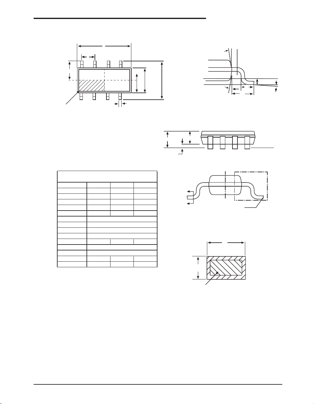
PACKAGE: 8 PIN NSOIC
D
e
Ø
INDEX AREA
(D/2 X E1/2)
1
TOP VIEW
8 Pin NSOIC JEDEC MO-012 (AA) Variation
SYMBOL
MIN NOM MAX
A 1.35 - 1.75
A1 0.1 - 0.25
A2 1.25 - 1.65
b 0.31 - 0.51
c 0.17 - 0.24
D
E
E1
e
4.90 BSC
6.00 BSC
3.90 BSC
1.27 BSC
L 0.4 - 1.27
L1
L2
1.04 REF
0.25 BSC
ø0º-8º
ø1 5º - 15º
Note: Dimensions in (mm)
E1
E1/2
b
E
Seating Plane
Ø1
L1
VIEW C
A
A1
A2
B
B
SIDE VIEW
SEE VIEW C
b
c
L
L2
Gauge Plane
Seating Plane
Ø
BASE METAL
SECTION B-B
WITH PLATING
Date: 11/29/04 SP6121 Low Voltage, Synchronous Step Down PWM Controller © Copyright 2004 Sipex Corporation
15
Page 16
ORDERING INFORMATION
Part Number Operating Temperature Range Package Type
SP6121CN ............................................... 0˚C to +70˚C ........................................... 8-Pin nSOIC
SP6121CN/TR ......................................... 0˚C to +70˚C .......................................... 8-Pin nSOIC
Available in lead free packaging. To order add "-L" suffix to part number.
Example: SP6121CN/TR = standard; SP6121CN-L/TR = lead free
/TR = Tape and Reel
Pack quantity is 2,500 for NSOIC.
CLICK HERE TO ORDER SAMPLES
Corporation
ANALOG EXCELLENCE
Sipex Corporation
Headquarters and
Sales Office
233 South Hillview Drive
Milpitas, CA 95035
TEL: (408) 934-7500
FAX: (408) 935-7600
Sipex Corporation reserves the right to make changes to any products described herein. Sipex does not assume any liability arising out of the
application or use of any product or circuit described herein; neither does it convey any license under its patent rights nor the rights of others.
Date: 11/29/04 SP6121 Low Voltage, Synchronous Step Down PWM Controller © Copyright 2004 Sipex Corporation
16
 Loading...