

Page 1
1
2
3
4
5
6
7
14
13
12
11
V
CC
REF IN/CRYSTAL
OSCILLATOR CAPACITOR
NC
RF INPUT
V
EE
DP14
CPDIS
10
9
8DRIVE OUTPUT
CHARGE PUMP
TEST 2
TEST 1
NC
RF INPUT
NC
SP5070
V
CC
REF IN/CRYSTAL
OSCILLATOR CAPACITOR
NC
RF INPUT
V
EE
MP14
CPDIS
DRIVE OUTPUT
CHARGE PUMP
TEST 2
TEST 1
NC
RF INPUT
NC
1
2
3
4
5
6
7
14
13
12
11
10
9
8
SP5070F
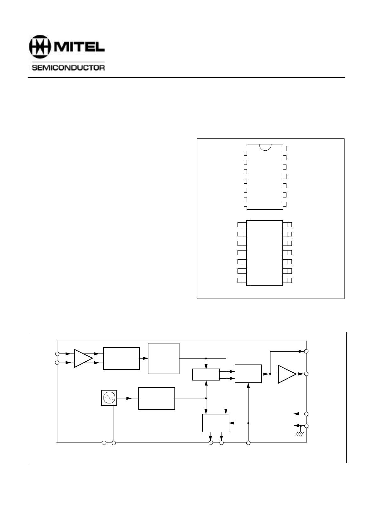
The SP5070 is a single modulus frequency synthesiser
for use in Satellite TV receivers and together with an
appropriate voltage controlled oscillator (VCO), forms a
complete phase locked loop (PLL) synthesiser. The circuit
consists of a prescaler with preamplifier and a fixed modulus
divider. The phase comparator is fed with a reference
frequency derived from an external oscillator or crystal. The
comparator has a charge pump output amplifier stage
around which feedback may be applied. Only an external
transistor is required for varicap line driving.
FEATURES
■ Low Power Consumption (5V, 47mA typ.)
■ Prescaler and Preamplifier Included
■ Charge Pump Amplifier with Feedback Point
■ Charge Pump Disable Facility
■ Synthesises Frequencies up to 2.4GHz
■ Pin and Function Compatible with SP5060 and
SP5062
■ Full ESD Protection*
* Normal ESD handling procedures should be observed.
APPLICATIONS
■ Satellite TV
■ High IF Cable Tuning Systems
■ C-Band with Frequency Doubling Mixer
ORDERING INFORMATION
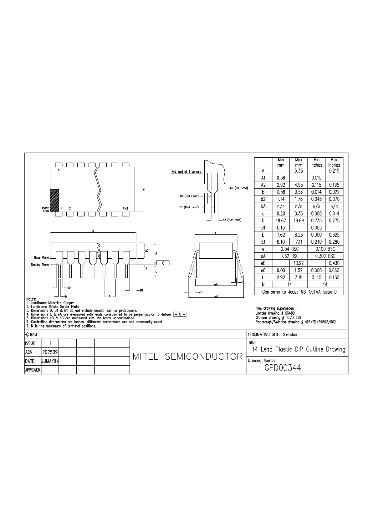
SP5070 DP - (14 Lead Plastic Package)
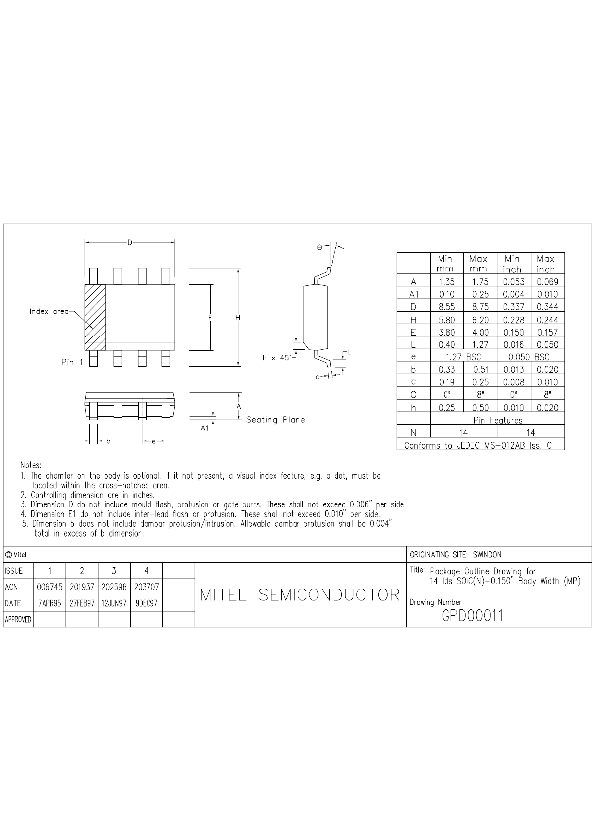
SP5070F MP - (14 Lead Miniature Plastic Package)
Fig.1 Pin connections - top view
Fig.2 Block diagram of SP5070
RF IN
RF IN
OSCILLATOR
CAPACITOR
REF IN/
CRYSTAL
TEST 1 TEST 2
CPDIS
PUMP
DRIVE
V
CC
V
EE
FDIV
FCOMP
CHARGE
PUMP
FIXED
MODULUS
DIVIDER
÷8192
8
7
1
6
11
13
149 10
2
3
OUTPUT
BUFFER
COMP
PHASE
PRESCALER
÷32
PRE
AMP
REFERENCE
DIVIDER
÷1024
SP5070
2.GHz Fixed Modulus Frequency Synthesiser
DS3966-2.2 May 996
Page 2
SP5070
2
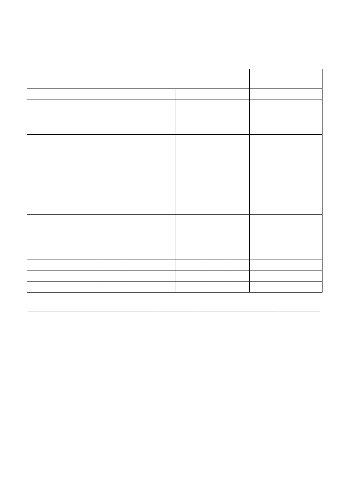
ELECTRICAL CHARACTERISTICS
Tamb = -40°C to +85°C,VCC = +4.5V to +5.5V. These characteristics are guaranteed by either production test or design.
They apply within the specified ambient temperature and supply voltage ranges unless otherwise stated.
Characteristics Symbol Pin
Min
Value
Typ Max
Units Conditions
Supply current I
CC
1 - 47 55 mA VCC = 5V
Prescaler input voltage
Prescaler input voltage
2,3
2,3
50
100
-
-
300
300
mV
RMS
mV
RMS
300MHz to 1.8GHz sinewave
2.4GHz, see Fig.5
Prescaler input impedance
Input capacitance
2,3
2,3
-
-
50
2
-
-
Ω
pF
Charge pump output current
Charge pump output leakage
Drift due to leakage
Charge pump drive output
current
Charge pump amplifier gain
8
8
-
7
-
-
-
-
1
-
±100
-
-
-
6400
-
±5
5
-
-
µA
nA
mV/s
mA
-
V pin 8 = 2.0V
V pin 8 = 2.0V
At collector of External
Varicap Drive transistor
V pin 7 = 0.7V
pin 7 current 100µa
Oscillator temperature stability
Oscillator stability with
supply voltage
9,10
9,10
-
-
-
-
2
2
ppm/°C
ppm/V
Reference clock frequency
External reference amplitude
10
10
2
150
-
-
10
500
MHz
mV
RMS
Charge pump disable/TEST 1
and TEST 2/enable
Charge pump disable leakage
11
11
-250
-
-
-
-500
10
µA
µA
VIN<0V
V pin 11= V
CC
TEST 1/TEST 2 sink current 13,14 1 - - mA VOUT = 0.7V
TEST 1/TEST 2 leakage current 13,14 - - 10 µA VOUT = VCC+0.3V
TEST 1/TEST 2 voltage 13,14 - - VCC+0.3 V
ABSOLUTE MAXIMUM RATINGS
All voltages are referred to VEE = 0V
Characteristics Pin
Value
Units
Min Max
Supply voltage
RF input voltage
RF input DC offset
Charge pump DC offset
Charge pump disable
Drive DC offset
Crystal oscillator DC offset
TEST outputs
Storage temperature
Junction temperature
DP14 thermal resistance, chip-to-ambient
DP14 thermal resistance, chip-to-case
MP14 thermal resistance, chip-to-ambient
MP14 thermal resistance, chip-to-case
Power consumption at 5.5V
1
2,3
2,3
8
11
7
9,10
13,14
-
-
-
-
-
-
-
-0.3
-
-0.3
-0.3
-0.7
-0.3
-0.3
-0.3
-55
-
-
-
-
-
-
7
2.5
VCC+0.3
VCC+0.3
VCC+0.3
VCC+0.3
VCC+0.3
VCC+0.3
150
+150
78
30
123
45
275
V
Vp-p
V
V
V
V
V
V
°C
°C
°C/W
°C/W
°C/W
°C/W
mW
Page 3
SP5070
3
FUNCTIONAL DESCRIPTION
The SP5070, when used with a voltage controlled
oscillator, forms a complete phase locked loop frequency
synthesiser.
The phase comparator comparison frequency is
obtained by dividing the reference frequency. This may be
generated on-chip by means of an external crystal, or from
an external reference oscillator.
The output of the prescaler is divided by the fixed
modulus divider, producing an output frequency which is
phased locked to the comparison frequency.
The divider stages are arranged to give a fixed ratio
between the synthesised frequency and the reference of
256:1. Any frequency within the range of 300MHz to 2.4GHz
may be achieved by using the appropriate reference or
crystal frequency.
A single external transistor, driven from the charge
pump output, provides the output drive necessary for the
oscillator varicap line.
A test facility which disables the charge pump is also
provided. This is activated when a negative voltage is
applied to pin 11, see electrical characteristics above. When
the device is in this mode, F
COMP
and F
DIV
are also available
at outputs TEST1 and TEST2 respectively. These are open
collector outputs and are each capable of sinking a minimum
of 1mA. In normal mode of operation these outputs are high
impedance.
For compatibility with SP5060/SP5062, pin 11 may be
connected toV
CC
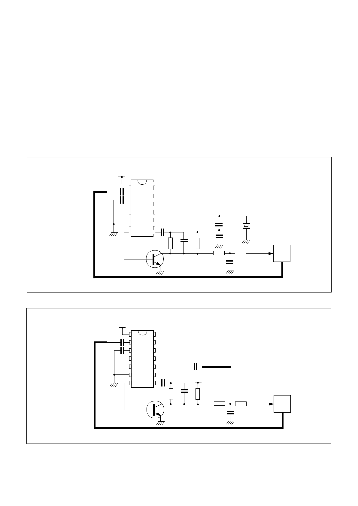
Fig.3 Typical application and test circuit (1024MHz with 4MHz reference crystal)
Fig.4 Application using external reference oscillator
1
2
3
4
5
6
7
14
13
12
11
DP14
10
9
8
S
P
5
0
7
0
+5V
1n
1n
FROM
VCO
2N3904
10K
47K
10n
22K
22K
47n
180n
+30V
100p
FROM
REFERENCE
OSCILLATOR
VARICAP
INPUT
VCO
1
2
3
4
5
6
7
14
13
12
11
10
9
8
S
P
5
0
7
0
+5V
1n
1n
FROM
VCO
2N3904
10K
47K
10n
22K
22K
47n
180n
+30V
68p
4MHz
REFERENCE
CRYSTAL
VARICAP
INPUT
VCO
47P
Page 4
SP5070
4
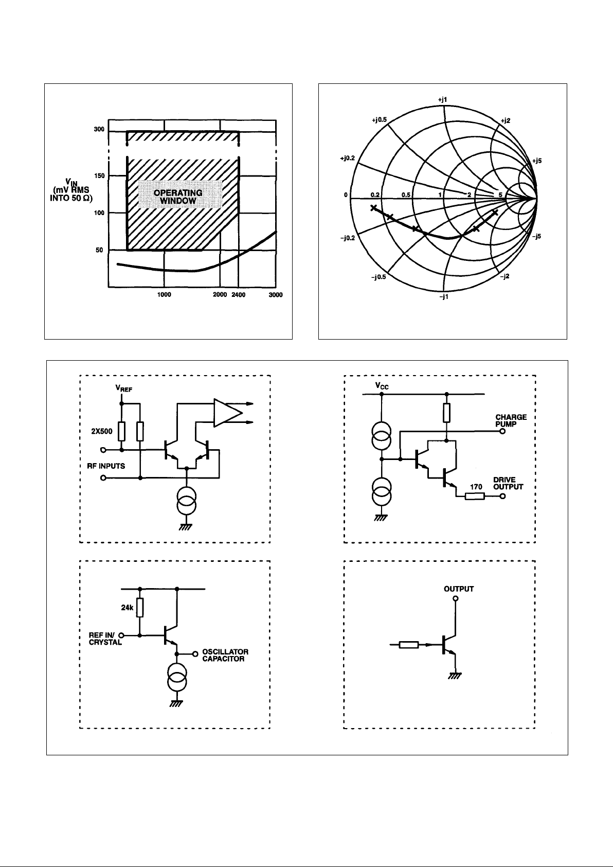
Fig.5 Typical input sensitivity Fig.6 Typical input impedance
Fig.7 SP5070 input/output interface circuits
S
11
:Z
0
= 50 Ω
FREQUENCY MARKER
STEP = 500MHz
RF input Loop amplifier
Reference oscillator
TEST 1and TEST 2 outputs
Page 5
Page 6
Page 7

M Mitel (design) and ST-BUS are registered trademarks of MITEL Corporation
Mitel Semiconductor is an ISO 9001 Registered Company
Copyright 1999 MITEL Corporation
All Rights Reserved
Printed in CANADA
TECHNICAL DOCUMENTATION - NOT FOR RESALE
World Headquarters - Canada
Tel: +1 (613) 592 2122
Fax: +1 (613) 592 6909
North America Asia/Pacific Europe, Middle East,
Tel: +1 (770) 486 0194 Tel: +65 333 6193 and Africa (EMEA)
Fax: +1 (770) 631 8213 Fax: +65 333 6192 Tel: +44 (0) 1793 518528
Fax: +44 (0) 1793 518581
http://www.mitelsemi.com
Information relating to products and services furnished herein by Mitel Corporation or its subsidiaries (collectively “Mitel”) is believed to be reliable. However, Mitel assumes no
liability for errors that may appear in this publication, or for liability otherwise arising from the application or use of any such information, product or ser vice or for any infringement of
patents or other intellectual property rights owned by third parties which may result from such application or use. Neither the supply of such information or purchase of product or
service conveys any license, either express or implied, under patents or other intellectual property rights owned by Mitel or licensed from third parties by Mitel, whatsoever.
Purchasers of products are also hereby notified that the use of product in certain ways or in combination with Mitel, or non-Mitel furnished goods or services may infringe patents or
other intellectual property rights owned by Mitel.
This publication is issued to provide information only and (unless agreed by Mitel in writing) may not be used, applied or reproduced for any purpose nor form par t of any order or
contract nor to be regarded as a representation relating to the products or services concerned. The products, their specifications, services and other information appearing in this
publication are subject to change by Mitel without notice. No warranty or guarantee express or implied is made regarding the capability, performance or suitability of any product or
service. Information concerning possible methods of use is provided as a guide only and does not constitute any guarantee that such methods of use will be satisfactory in a specific
piece of equipment. It is the user’s responsibility to fully determine the performance and suitability of any equipment using such information and to ensure that any publication or
data used is up to date and has not been superseded. Manufacturing does not necessarily include testing of all functions or parameters. These products are not suitable for use in
any medical products whose failure to perform may result in significant injury or death to the user. All products and materials are sold and services provided subject to Mitel’s
conditions of sale which are available on request.
 Loading...