

Page 1
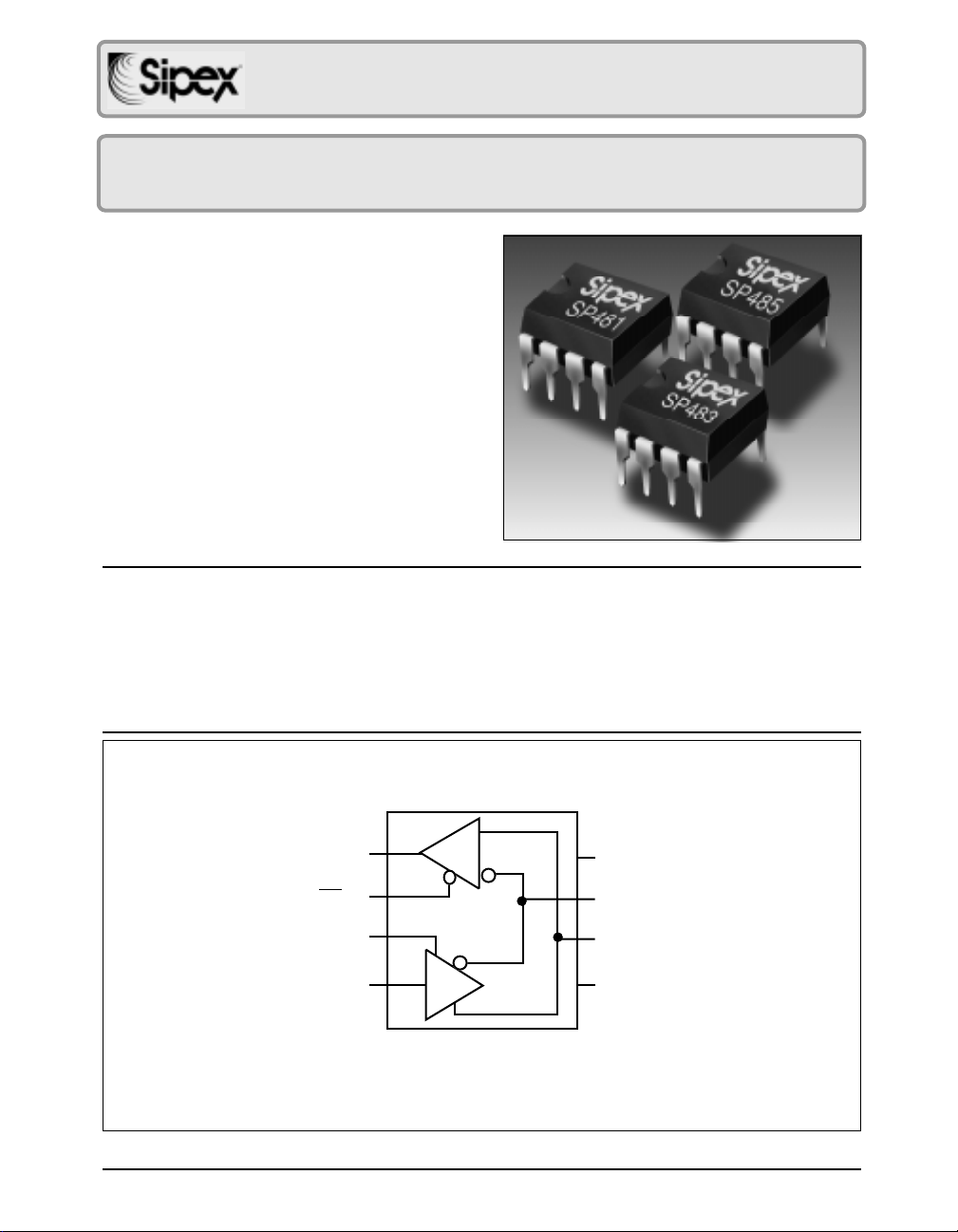
SP481/SP483/SP485
O
Low Power Half-Duplex RS-485 Transceivers
■ +5V Only
■ Low Power BiCMOS
■ Driver/Receiver Enable
■ Slew Rate Limited Driver for
Low EMI (SP483)
■ Low Power Shutdown Mode (SP481
and SP483)
■ RS-485 and RS-422 Drivers/Receivers
DESCRIPTION
The SP481, SP483, and the SP485 are a family of half-duplex transceivers that meet the
requirements of RS-485 and RS-422. Their BiCMOS design allows low power operation
without sacrificing performance. The SP481 and SP485 meet the requirements of RS-485
and RS-422 up to 5Mbps. Additionally, the SP481 is equipped with a low power Shutdown
mode. The SP483 is internally slew rate limited to reduce EMI and can meet the requirements
of RS-485 and RS-422 up to 250kbps. The SP483 is also equipped with a low power
Shutdown mode.
R
1
RE
2
RE
DE
3
DI
4
SP481, SP483, and SP485
SP481/483/485DS/09 SP481/483/485 Low Power Half-Duplex RS485 Transceivers © Copyright 2000 Sipex Corporation
D
R
Vcc
8
B
7
A
6
GND
5
1
Page 2
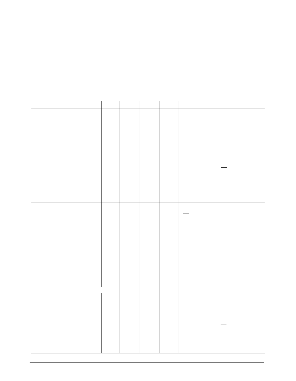
ABSOLUTE MAXIMUM RATINGS
These are stress ratings only and functional operation of the device at
these ratings or any other above those indicated in the operation sections
of the specifications below is not implied. Exposure to absolute maximum
rating conditions for extended periods of time may affect reliability.
VCC............................................................................................................±12V
Input Voltages
Output Voltages
Storage Temperature.......................................................-65˚C to +150˚C
Power Dissipation...........................................................................500mW
Logic........................................................-0.3V to (VCC+0.5V)
Drivers..................................................-0.3V to (VCC+0.5V)
Receivers................................................................. ±15V
Logic........................................................-0.3V to (VCC+0.5V)
Drivers...................................................................... ±15V
Receivers............................................-0.3V to (VCC+0.5V)
SPECIFICATIONS
T
to T
and VCC = 5V ± 5% unless otherwise noted.
MIN
MAX
PARAMETERS MIN. TYP. MAX. UNITS CONDITIONS
SP481/SP483/SP485 DRIVER
DC Characteristics
Differential Output Voltage GND V
Differential Output Voltage 2 V
Differential Output Voltage 1.5 V
Change in Magnitude of Driver
Differential Output Voltage for
Complimentary States 0.2 Volts R = 27Ω or R = 50Ω;
Driver Common-Mode
Output Voltage 3 Volts R = 27Ω or R = 50Ω;
Input High Voltage 2.0 Volts Applies to DE, DI, RE
Input Low Voltage 0.8 Volts Applies to DE, DI, RE
Input Current ±10 µA Applies to DE, DI, RE
Driver Short-Circuit Current
V
= HIGH 35 250 mA -7V ≤ VO ≤ +12V
OUT
V
= LOW 35 250 mA -7V ≤ VO ≤ +12V
OUT
SP481/SP485 DRIVER
AC Characteristics
Maximum Data Rate 5 Mbps RE = 5V, DE = 5V
Driver Input to Output 20 30 60 ns t
Driver Input to Output 20 30 60 ns t
Driver Skew 5 10 ns
Driver Rise or Fall Time 3 15 40 ns From 10% to 90%; R
Driver Enable to Output High 40 70 ns C
Driver Enable to Output Low 40 70 ns C
Driver Disable Time from Low 40 70 ns C
Driver Disable Time from High 40 70 ns C
SP481/SP483/SP485
RECEIVER
DC Characteristics
Differential Input Threshold -0.2 +0.2 Volts -7V ≤ V
Input Hysteresis 10 mV VCM = 0V
Output Voltage High 3.5 Volts IO = -4mA, VID = +200mV
Output Voltage Low 0.4 Volts IO = +4mA, VID = -200mV
Three-State (High Impedance)
Output Current ±1 µA 0.4V ≤ VO ≤ 2.4V; RE = 5V
Input Resistance 12 15 kΩ -7V ≤ V
Input Current (A, B); VIN = 12V +1.0 mA DE = 0V, VCC = 0V or 5.25V, VIN = 12V
Input Current (A, B); VIN = -7V -0.8 mA DE = 0V, VCC = 0V or 5.25V, VIN = -7V
Short-Circuit Current 7 95 mA 0V ≤ VCM ≤ V
Volts Unloaded; R = ∞ ;
CC
Volts with load; R = 50Ω; (RS422);
CC
Volts with load; R = 27Ω; (RS485);
CC
see figure 1
; R
PLH
see figures 3 and 6
PHL
see figures 3 and 6
= 54Ω, CL1 = CL2 = 100pF;
DIFF
; R
= 54Ω, CL1 = CL2 = 100pF;
DIFF
see figures 3 and 6,
t
= | t
SKEW
CL1 = C
= 100pF;
L
= 100pF;
L
= 15pF;
L
= 15pF;
L
- t
DPLH
= 100pF;
L2
see figures 4 & 7;
see figures 4 & 7;
see figures 2 & 9;
see figures 2 & 9;
≤ +12V
CM
≤ +12V
CM
CC
see figure 1
see figure 1
see figure 1
see figure 1
|
DPHL
= 54Ω,
DIFF
see figures 3 and 6
S2 closed
S1 closed
S1 closed
S2 closed
SP481/483/485DS/09 SP481/483/485 Low Power Half-Duplex RS485 Transceivers © Copyright 2000 Sipex Corporation
2
Page 3
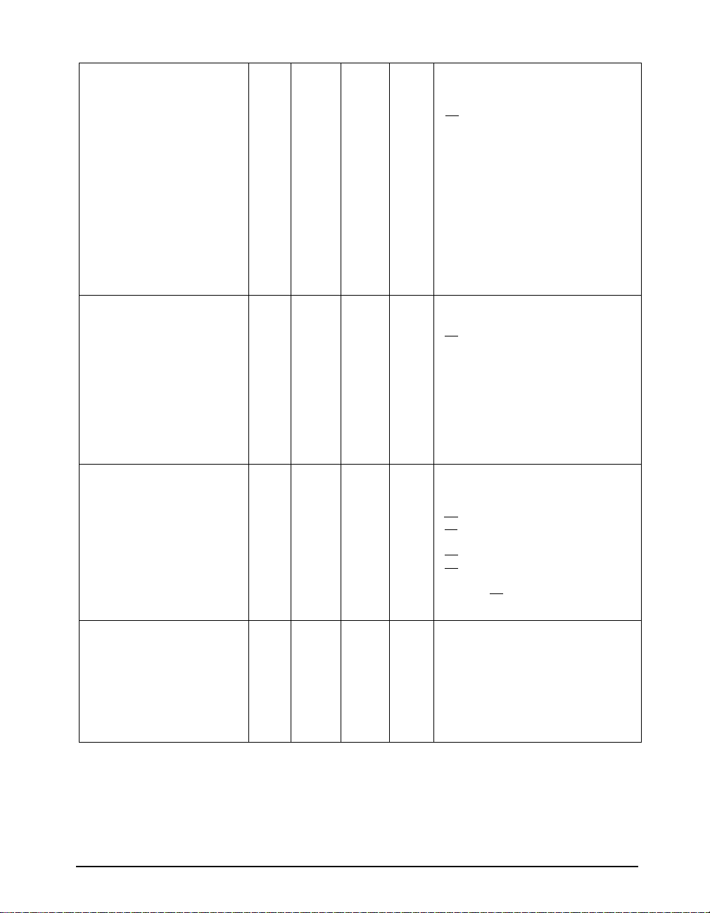
SPECIFICATIONS (continued)
T
to T
and VCC = 5V ± 5% unless otherwise noted.
MIN
MAX
PARAMETERS MIN. TYP. MAX. UNITS CONDITIONS
SP481/SP485 RECEIVER
AC Characteristics
Maximum Data Rate 5 Mbps RE = 0V, DE = 0V
Receiver Input to Output 60 90 200 ns t
Receiver Input to Output 60 90 200 ns t
Diff. Receiver Skew It
I 13 ns R
PLH-tPHL
Receiver Enable to
Output Low 20 50 ns C
Receiver Enable to
Output High 20 50 ns C
Receiver Disable from Low 20 50 ns C
Receiver Disable from High 20 50 ns C
SP481
Shutdown Timing
Time to Shutdown 50 200 600 ns RE = 5V, DE = 0V
Driver Enable from Shutdown
to Output High 40 100 ns CL = 100pF;
Driver Enable from Shutdown
to Output Low 40 100 ns CL = 100pF;
Receiver Enable from
Shutdown to Output High 300 1000 ns CL = 15pF;
Receiver Enable from
Shutdown to Output Low 300 1000 ns CL = 15pF;
; R
PLH
DIFF
CL1 = C
L2
; R
PHL
DIFF
CL1 = C
L2
= 54Ω; C
DIFF
Figures 3 & 8
= 15pF;
RL
= 15pF;
RL
= 15pF;
RL
= 15pF;
RL
= 100pF;
=
Figures 2 & 9;
= 54Ω,
= 54Ω,
Figures 3 & 8
100pF;
Figures 3 & 8
= C
= 100pF;
L1
L2
Figures 2 & 9;
Figures 2 & 9;
Figures 2 & 9;
S1 closed
S2 closed
S1 closed
S2 closed
See figures 4 & 7;
See figures 4 & 7;
See figures 2 & 9;
See figures 2 & 9;
S2 closed
S1 closed
S2 closed
S1 closed
POWER REQUIREMENTS
Supply Voltage +4.75 +5.25 Volts
Supply Current
SP481/485
No Load 900 mA RE, DI = 0V or VCC; DE = V
µA RE = 0V, DI = 0V or 5V; DE = 0V
CC
SP483
No Load 600 µA RE, DI = 0V or VCC; DE = V
µA RE=0V, DI = 0V or 5V; DE = 0V
CC
SP481/SP483
Shutdown Mode 10 µA DE = 0V, RE=V
CC
ENVIRONMENTAL AND
MECHANICAL
Operating Temperature
Commercial (_C_) 0 +70 °C
Industrial (_E_) -40 +85 °C
Storage Temperature -65 +150 °C
Package
Plastic DIP (_S)
NSOIC (_N)
SP481/483/485DS/09 SP481/483/485 Low Power Half-Duplex RS485 Transceivers © Copyright 2000 Sipex Corporation
3
Page 4
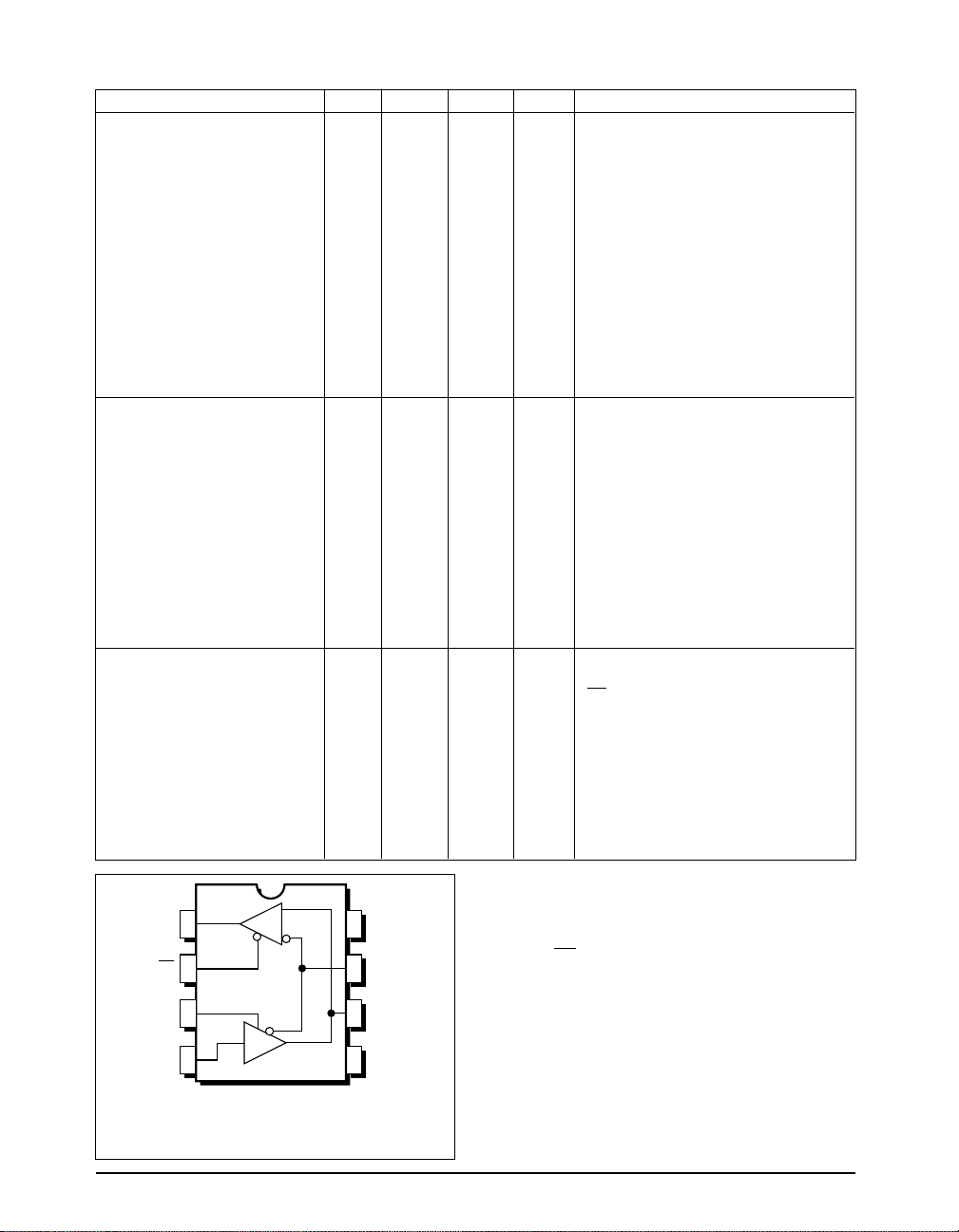
SP483 AC SPECIFICATIONS
T
to T
and VCC = 5V ± 5% unless otherwise noted.
MIN
MAX
PARAMETERS MIN. TYP. MAX. UNITS CONDITIONS
SP483 DRIVER
AC Characteristics
Maximum Data Rate 250 kbps
Driver Input to Output 250 800 2000 ns t
Driver Skew 250 800 2000 ns t
Driver Rise and Fall Time 100 800 ns
250 2000 ns From 10% to 90%; R
Driver Enable to Output High 250 2000 ns CL = 100pF;
Driver Enable to Output Low 250 2000 ns CL = 100pF;
Driver Disable Time from Low 300 3000 ns CL = 15pF;
Driver Disable Time from High 300 3000 ns CL = 15pF;
SP483 RECEIVER
AC Characteristics
Maximum Data Rate 250 kbps
Receiver Input to Output 250 2000 ns t
Diff. Receiver Skew It
I 100 ns R
PLH-tPHL
Receiver Enable to
Output Low 20 50 ns C
Receiver Enable to
Output High 20 50 ns C
Receiver Disable from Low 20 50 ns C
Receiver Disable from High 20 50 ns C
; R
PLH
see figures 3 & 6
; R
PHL
see figures 3 & 6
see figures 3 & 6,
t
= |t
SKEW
CL1 = CL2 = 100pF,
; R
PLH
Figures 3 & 8
= 54Ω, CL1 = C
DIFF
Figures 3 & 8
= 15pF;
RL
= 15pF;
RL
= 15pF;
RL
= 15pF;
RL
= 54Ω, CL1 = C
DIFF
= 54Ω, CL1 = C
DIFF
- t
DPLH
DPHL
See figures 4 & 7;
See figures 4 & 7;
See figures 4 & 7;
See figures 4 & 7;
= 54Ω, CL1 = C
DIFF
Figures 2 & 9;
Figures 2 & 9;
Figures 2 & 9;
Figures 2 & 9;
=
100pF;
L2
=
100pF;
L2
|
= 54Ω,
DIFF
see figures 3 & 6
S2 closed
S1 closed
S1 closed
S2 closed
= 100pF;
L2
= 100pF;
L2
S1 closed
S2 closed
S1 closed
S2 closed
SP483
Shutdown Timing
Time to Shutdown 50 200 600 ns RE = 5V, DE = 0V
Driver Enable from Shutdown
to Output High 2000 ns CL = 100pF;
See figures 4 & 7;
S2 closed
Driver Enable from Shutdown
to Output Low 2000 ns CL = 100pF;
See figures 4 & 7;
S1 closed
Receiver Enable from
Shutdown to Output High 2500 ns CL = 15pF;
See figures 4 & 7;
S2 closed
Receiver Enable from
Shutdown to Output Low 2500 ns CL = 15pF;
See figures 4 & 7;
S1 closed
PIN FUNCTION
RO 1
RE 2
DE 3
DI 4
R
D
SP485
8 V
CC
7 B
6 A
5 GND
Top View
SP481, SP483, SP485
Pinout (Top View)
SP481/483/485DS/09 SP481/483/485 Low Power Half-Duplex RS485 Transceivers © Copyright 2000 Sipex Corporation
Pin# Name Description
1 RO Receiver Output.
2 RE Receiver Output Enable
Active LOW.
3 DE Driver Output Enable
Active HIGH.
4 DI Driver Input.
5 GND Ground Connection.
6 A Driver Output/Receiver Input
Non-inverting.
7 B Driver Output/Receiver Input
Inverting.
8 Vcc Positive Supply 4.75V<Vcc< 5.25V.
4
Page 5

DESCRIPTION
SP481, SP483, SP485
Receivers
SP481, SP483, SP485
The SP481, SP483, and SP485 are half-duplex
differential transceivers that meet the requirements of RS-485 and RS-422. Fabricated with a
Sipex proprietary BiCMOS process, all three
products require a fraction of the power of older
bipolar designs.
The RS-485 standard is ideal for multi-drop
applications and for long-distance interfaces.
RS-485 allows up to 32 drivers and 32 receivers
to be connected to a data bus, making it an ideal
choice for multi-drop applications. Since the
cabling can be as long as 4,000 feet, RS-485
transceivers are equipped with a wide (-7V to
+12V) common mode range to accommodate
ground potential differences. Because RS-485 is
a differential interface, data is virtually immune
to noise in the transmission line.
Drivers
SP481, SP483, SP485
The driver outputs of the SP481, SP483, and
SP485 are differential outputs meeting the RS-
485 and RS-422 standards. The typical voltage
output swing with no load will be 0 volts to +5
volts. With worst case loading of 54Ω across the
differential outputs, the drivers can maintain
greater than 1.5V voltage levels. The drivers of
the SP481, SP483 and SP485 have an enable
control line which is active HIGH. A logic
HIGH on DE (pin 5) will enable the differential
driver outputs. A logic LOW on DE (pin 5) will
tri-state the driver outputs.
The SP481, SP483, and SP485 receivers have
differential inputs with an input sensitivity as
low as ±200mV. Input impedance of the receivers is typically 15kΩ (12kΩ minimum). A wide
common mode range of -7V to +12V allows for
large ground potential differences between
systems. The receivers of the SP481, SP483
and SP485 have a tri-state enable control pin.
A logic LOW on RE (pin 4) will enable the
receiver, a logic HIGH on RE (pin 4) will disable
the receiver.
The receiver for the SP481 and SP485 will
operate up to at least 5Mbps. The SP483 receiver
is rated for data rates up to 250kbps. The receiver
for each of the three devices is equipped with the
fail-safe feature. Fail-safe guarantees that the
receiver output will be in a HIGH state when the
input is left unconnected.
Shutdown Mode
SP481/SP483
The SP481 and SP483 are equipped with a
Shutdown mode. To enable the Shutdown state,
both the driver and receiver must be disabled
simultaneously. A logic LOW on DE (pin 5) and
a logic HIGH on RE (pin 4) will put the SP481
or SP483 into Shutdown mode. In Shutdown,
supply current will drop to typically 1µA.
The transmitters of the SP481 and SP485 will
operate up to at least 5Mbps. The SP483 has
internally slew rate limited driver outputs to
minimize EMI. The maximum data rate for the
SP483 driver is 250kbps.
SP481/483/485DS/09 SP481/483/485 Low Power Half-Duplex RS485 Transceivers © Copyright 2000 Sipex Corporation
5
Page 6
A
R
V
OD
V
OC
R
Receiver
Output
C
RL
1K
B
1KTest Point
S
1
S
2
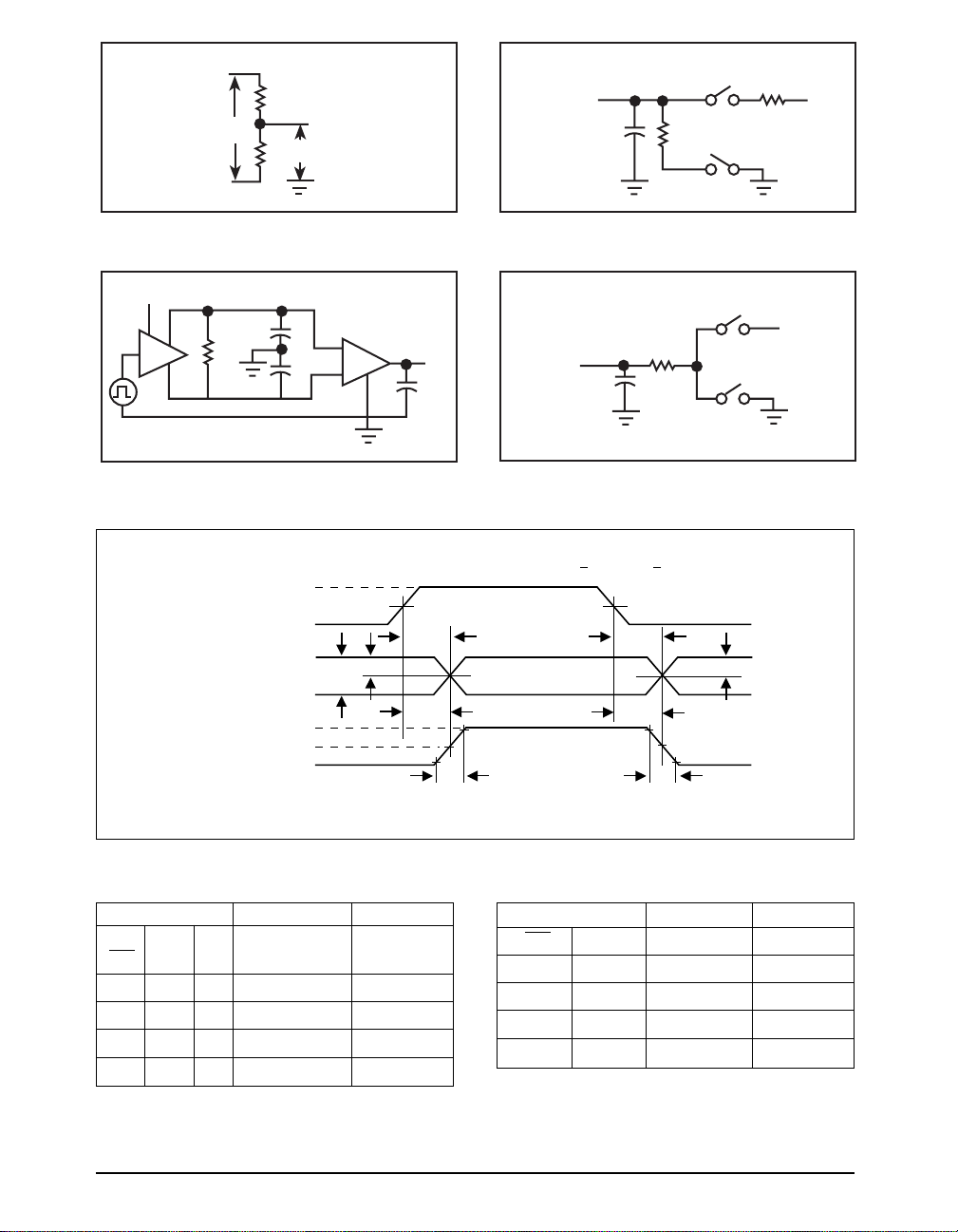
Figure 1. Driver DC Test Load Circuit Figure 2. Receiver Timing Test Load Circuit
3V
DE
DI
A
B
R
C
DIFF
L1
C
L2
A
B
RO
15pF
Output
Under
Test
C
500
L
S
S
V
1
2
CC
Figure 3. Driver/Receiver Timing Test Circuit Figure 4. Driver Timing Test Load #2 Circuit
V
CC
+3V
DI
0V
DRIVER
OUTPUT
DIFFERENTIAL
OUTPUT
VA – V
t
SKEW = | tDPLH - tDPHL |
Figure 6. Driver Propagation Delays
B
A
+
V
O
0V
–
V
O
B
f
SP481/485 =
V
O
1MHz; f
1.5V 1.5V
1/2V
O
INPUTS OUTPUTS
LINE
RE DE DI CONDITION B A
X 1 1 No Fault 0 1
X 1 0 No Fault 1 0
X0X X ZZ
X 1 X Fault Z Z
Table 1. Transmit Function Truth Table
100kHz ; tR < 10ns; tF < 10ns
SP483 =
t
PLH
t
DPLH
t
R
t
PHL
t
DPHL
INPUTS OUTPUTS
RE DE A - B R
0 0 +0.2V 1
0 0 -0.2V 0
0 0 Inputs Open 1
10 X Z
Table 2. Receive Function Truth Table
t
F
1/2V
O
SP481/483/485DS/09 SP481/483/485 Low Power Half-Duplex RS485 Transceivers © Copyright 2000 Sipex Corporation
6
Page 7
f
SP481/485
= 1MHz; f
= 100kHz; tR < 10ns; tF < 10ns
SP483
+3V
DE
1.5V 1.5V
0V
5V
A, B
V
OL
V
OH
A, B
0V
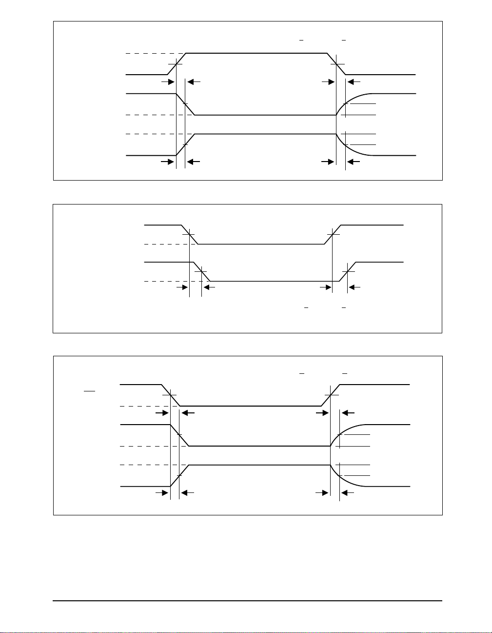
Figure 7. Driver Enable and Disable Times
+
V
0D2
A – B
t
SKEW = | tPHL - tPLH
–
V
0D2
V
OH
R
V
OL
t
PHL
f
SP481/485
|
t
ZL
2.3V
2.3V
Output normally LOW
Output normally HIGH
t
ZH
0V 0V
1.5V 1.5V
= 1MHz; f
INPUT
OUTPUT
t
PLH
= 100kHz; tR < 10ns; tF < 10ns
SP483
0.5V
0.5V
t
LZ
t
HZ
Figure 8. Receiver Propagation Delays
f
SP481/485
= 1MHz; f
= 100kHz; tR < 10ns; tF < 10ns
SP483
+3V
RE
0V
1.5V 1.5V
t
ZL
t
LZ
5V
R
V
IL
V
IH
R
0V
Figure 9. Receiver Enable and Disable Times
SP481/483/485DS/09 SP481/483/485 Low Power Half-Duplex RS485 Transceivers © Copyright 2000 Sipex Corporation
1.5V
1.5V
Output normally LOW
Output normally HIGH
t
ZH
0.5V
0.5V
t
HZ
7
Page 8
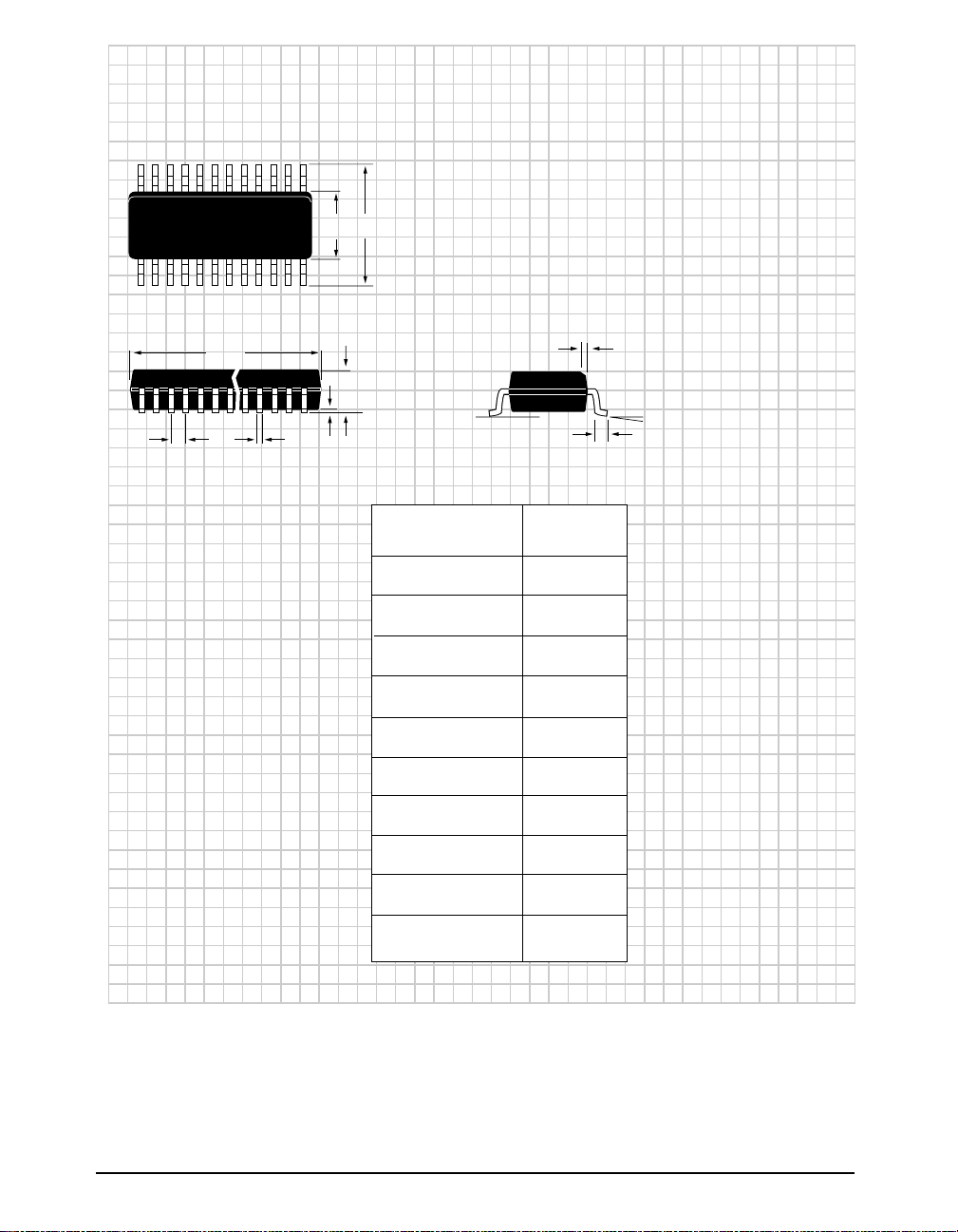
PACKAGE: PLASTIC
SMALL OUTLINE (SOIC)
(NARROW)
EH
h x 45°
D
A
Ø
Be
A1
DIMENSIONS (Inches)
Minimum/Maximum
(mm)
A
A1
B
D
E
e
H
h
L
Ø
0.053/0.069
(1.346/1.748)
0.004/0.010
(0.102/0.249
0.014/0.019
(0.35/0.49)
0.189/0.197
(4.80/5.00)
0.150/0.157
(3.802/3.988)
0.050 BSC
(1.270 BSC)
0.228/0.244
(5.801/6.198)
0.010/0.020
(0.254/0.498)
0.016/0.050
(0.406/1.270)
8–PIN
0°/8°
(0°/8°)
L
SP481/483/485DS/09 SP481/483/485 Low Power Half-Duplex RS485 Transceivers © Copyright 2000 Sipex Corporation
8
Page 9
D1 = 0.005" min.
(0.127 min.)
D
e = 0.100 BSC
(2.540 BSC)
B1
B
ALTERNATE
END PINS
(BOTH ENDS)
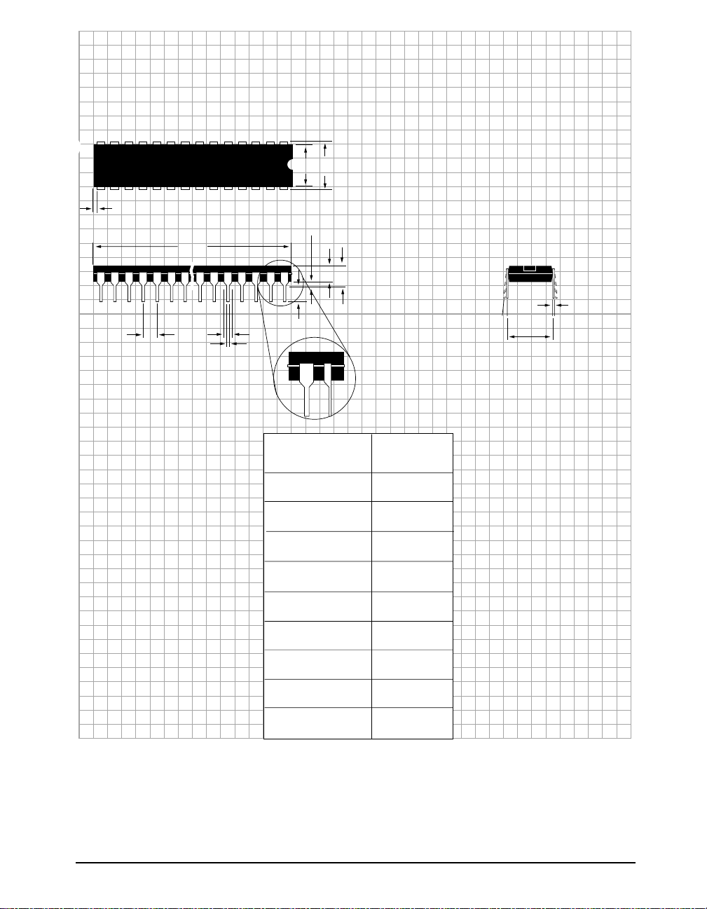
PACKAGE: PLASTIC
DUAL–IN–LINE
(NARROW)
E1
E
A1 = 0.015" min.
(0.381min.)
A = 0.210" max.
(5.334 max).
A2
L
C
Ø
eA = 0.300 BSC
(7.620 BSC)
DIMENSIONS (Inches)
Minimum/Maximum
(mm)
A2
B
B1
C
D
E
E1
L
Ø
8–PIN
0.115/0.195
(2.921/4.953)
0.014/0.022
(0.356/0.559)
0.045/0.070
(1.143/1.778)
0.008/0.014
(0.203/0.356)
0.355/0.400
(9.017/10.160)
0.300/0.325
(7.620/8.255)
0.240/0.280
(6.096/7.112)
0.115/0.150
(2.921/3.810)
0°/ 15°
(0°/15°)
SP481/483/485DS/09 SP481/483/485 Low Power Half-Duplex RS485 Transceivers © Copyright 2000 Sipex Corporation
9
Page 10
ORDERING INFORMATION
Model Temperature Range Package
SP481CN...................................................................................... 0˚C to +70˚C .......................................................................... 8-pin Narrow SOIC
SP481CS ...................................................................................... 0˚C to +70˚C ............................................................................8-pin Plastic DIP
SP481EN .................................................................................... .-40˚C to +85˚C ........................................................................ 8-pin Narrow SOIC
SP481ES .....................................................................................-40˚C to +85˚C ..........................................................................8-pin Plastic DIP
SP483CN...................................................................................... 0˚C to +70˚C .......................................................................... 8-pin Narrow SOIC
SP483CS ...................................................................................... 0˚C to +70˚C ............................................................................8-pin Plastic DIP
SP483EN ..................................................................................... -40˚C to +85˚C ........................................................................ 8-pin Narrow SOIC
SP483ES .....................................................................................-40˚C to +85˚C ..........................................................................8-pin Plastic DIP
SP485CN...................................................................................... 0˚C to +70˚C .......................................................................... 8-pin Narrow SOIC
SP485CS ...................................................................................... 0˚C to +70˚C ............................................................................8-pin Plastic DIP
SP485EN ..................................................................................... -40˚C to +85˚C ........................................................................ 8-pin Narrow SOIC
SP485ES .....................................................................................-40˚C to +85˚C ..........................................................................8-pin Plastic DIP
Please consult the factory for pricing and availability on a Tape-On-Reel option.
Corporation
SIGNAL PROCESSING EXCELLENCE
Sipex Corporation
Headquarters and
Sales Office
22 Linnell Circle
Billerica, MA 01821
TEL: (978) 667-8700
FAX: (978) 670-9001
e-mail: [email protected]
Sales Office
233 South Hillview Drive
Milpitas, CA 95035
TEL: (408) 934-7500
FAX: (408) 935-7600
Sipex Corporation reserves the right to make changes to any products described herein. Sipex does not assume any liability arising out of the
application or use of any product or circuit described hereing; neither does it convey any license under its patent rights nor the rights of others.
SP481/483/485DS/09 SP481/483/485 Low Power Half-Duplex RS485 Transceivers © Copyright 2000 Sipex Corporation
10
 Loading...