

Page 1
®
PRELIMINARY
SP4446
High Output Voltage Boost Regulator
LCD Bias Regulator
FEATURES
■ High Output Voltage: Up to 30V
■ High Efficiency
■ Low Quiescent Current: ~20uA
■ Miniature Package: (5-lead SOT-23)
■ Single Battery Cell Operation
■ Programmable Output Voltage
Now Available in Lead Free Packaging
V
IN
54
SP4446
5 Pin SOT-23
123
SW
GND
SHDN
FB
■ 1Ω Switch (150mV at 150mA)
APPLICATIONS
■ LCD Bias
■ Tuner Pin Voltage
■ White LED Driver
■ High Voltage Bias
■ Digital Cameras
■ Cell Phone
■ Battery Backup
■ Handheld Computers
DESCRIPTION
The SP4446 is a micro power Boost Regualtor in a 5-lead SOT-23 package. It is a current limited,
fixed off time regulator configured for use in boost mode applications. The operating voltage can
be less than 3V and is capable of generating voltages as high as 30 Volts.
The SP4446 is to be supplied in a SOT-23-5 and permits the construction of complete regulators
that occupy < 0.2 square inches of board space.
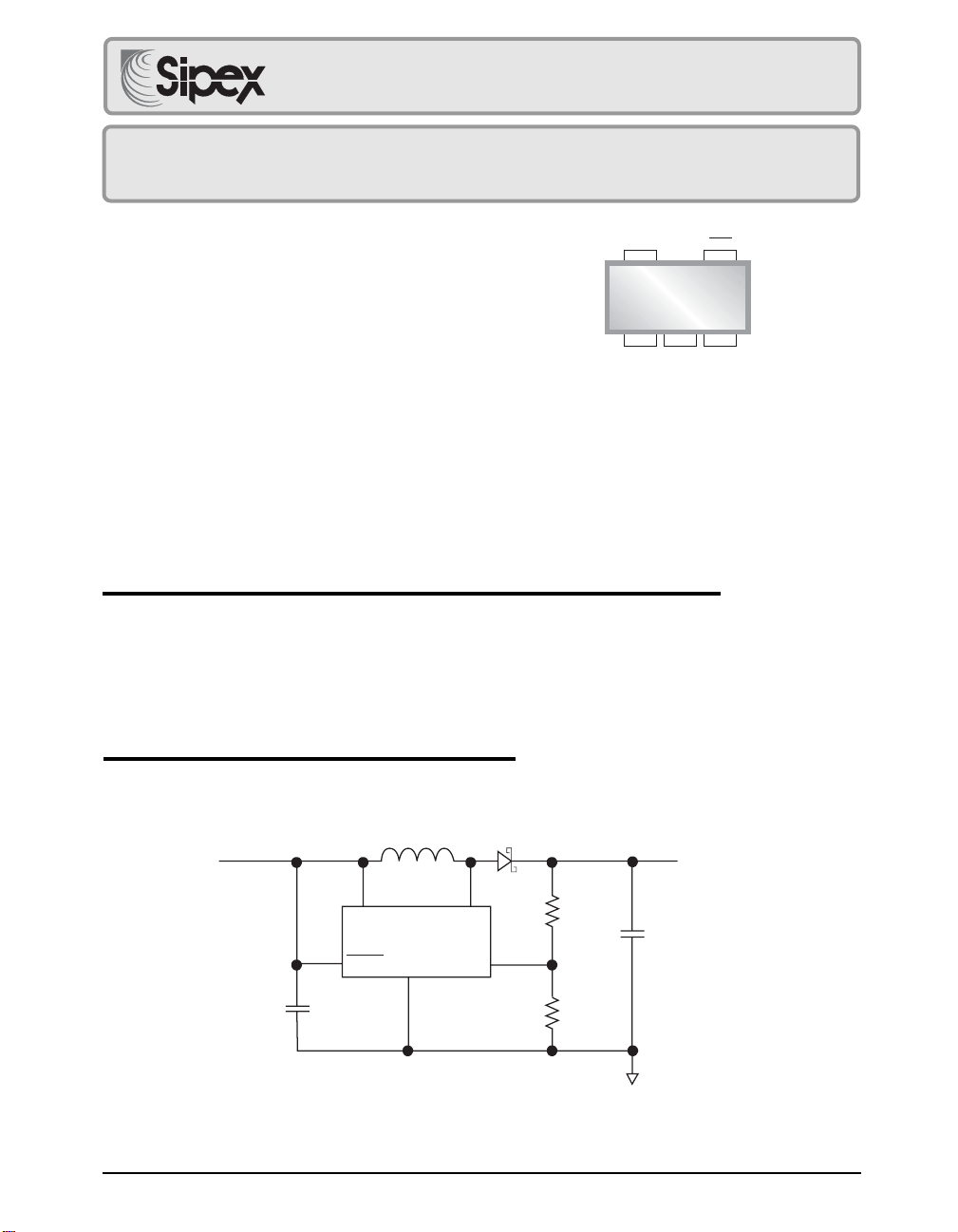
TYPICAL APPLICATION SCHEMATIC
V
IN
2 to 7V
V
SHDN
C1
4.7µF
Date: 11/29/04 SP4446 High Output Voltage Boost Regualtor, LCD Bias Regulator © Copyright 2004 Sipex Corporation
L1
10µH
IN
SP4446
GND
SW
FB
D1
R1
R2
High
Voltage Output
C2
2.2 µF
1
Page 2
ABSOLUTE MAXIMUM RATINGS
VIN....................................................................... 15V
SW Voltage .............................................. -0.4 to 34V
Lead Temperature (Soldering, 10 sec) ............ 300°C
ESD Rating................................................. 2kV HBM
FB Voltage.......................................................... 2.5V
All other pins.................................. -0.3 to VCC + 0.3V
Current into FB ................................................. ±1mA
TJ Max ............................................................. 125°C
Operating Temperature Range ............ -40°C to 85°C
Peak Output Current < 10us SW .................... 500mA
Storage Temperature ...................... -65°C to +150°C
These are stress ratings only and functional operation of
the device at these ratings or any other above those
indicated in the operation sections of the specifications
below is not implied. Exposure to absolute maximum
rating conditions for extended periods of time may affect
reliability.
Power Dissipation. ......................................... 200mW
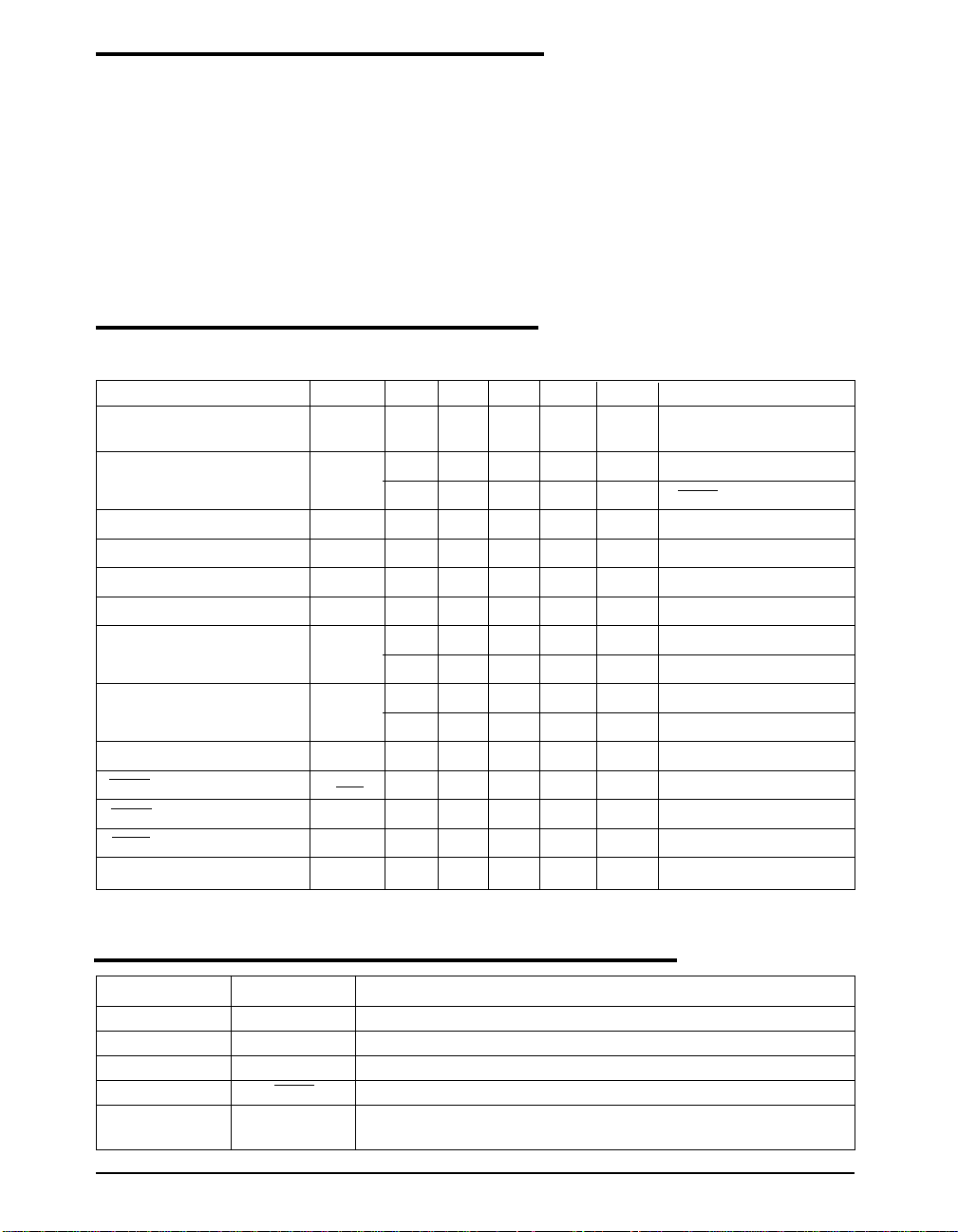
ELECTRICAL CHARACTERISTICS
Specifications are at VIN = 3.3V, V
temperature range, unless otherwise specified.
PARAMETER SYMBOL MIN TYP MAX UNITS CONDITIONS
Input voltage V
Supply Current I
Reference Voltage V
FB Hysteresis HYST 8 mV
VFB Input Bias Current I
Line Regulation ∆Vo/∆V
Switch Off Time T
Switch Saturation Voltage V
Switch Current Limit I
SHDN Bias Current I
SHDN High Threshold (on) V
SHDN Low Threshold (off) V
Switch Leakage Current I
= VIN, TA = 25°C, ♦ denotes the specifications which apply over the full operating
SHDN
1.0 8.0 V Switch Current Limit =
IN
Q
20 30 µA ♦ No Switching
150mA
0.01 1 µA SHDN = 0V
1.17 1.22 1.27 V ♦
FB
FB
OFF
CESAT
15 80 nA ♦ V
I
0.04 %/V 1.2 ≤ V
300 nS V
1200 nS V
50 mV ♦ ISW = 50mA
= 1.22V
FB
> 1V
FB
< 0.3V
FB
IN
150 mV ISW = 150mA
100 150 200 mA ♦
LIM
SHDN
IH
IL
SWLK
512µA ♦ V
0.9 V
0.25 V
25µA ♦ Switch Off, VSW = 5V
SHDN
= 5V
≤ 8V
PIN DESCRIPTION
PIN NUMBER PIN NAME DESCRIPTION
1SWSwitch input to the internal power switch.
2 GND Ground
3FBFeedback
4 SHDN Shutdown. Pull high (on) to enable. Pull low (off) for shutdown.
5VINInput Voltage. Bypass this pin with a capacitor as close to the device
as possible.
Date: 11/29/04 SP4446 High Output Voltage Boost Regualtor, LCD Bias Regulator © Copyright 2003 Sipex Corporation
2
Page 3
VI
(EXTERNAL)
(EXTERNAL)
FUNCTIONAL DIAGRAM
OUT
L1
V
C1
R5
R1
Q1
3
FB
R2
IN
R6
Q2
R3
R4
X1
+
-
DISABLE
SET
300ns
ONE-SHOT
CLEAR
X2
DRIVER
+
-
52.5mV
SW
TRANSISTOR
0.35
15
POWER
D1
C2
V
Shutdown
SHDN
4
Logic
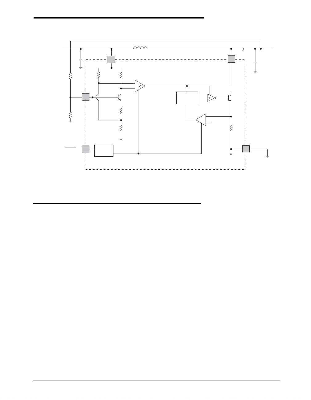
General Overview:
Operation can be best understood by referring to
the above block diagram. Q1 and Q2 along with
R3 and R4 form a band gap reference. The input
to this circuit completes a feedback path from
the high voltage output through a voltage divider, and is used as the regulation control input.
When the voltage at the FB pin is slightly above
1.22V, comparator X1 disables most of the
internal circuitry. Current is then provided by
capacitor C2, which slowly discharges until the
voltage at the FB pin drops below the lower
hysteresis point of X1, about 6mV. X1 then
enables the internal circuitry, turns on chip
power, and the current in the inductor begins to
ramp up. When the current through the driver
transistor reaches about 150mA, comparator X2
clears the latch, which turns off the driver transistor for a preset 0.3µs. At the instant of shutoff,
inductor current is diverted to the output through
diode D1. During this 0.3µs time limit, inductor
current decreases while its energy charges C2.
GND
2
THEORY OF OPERATION
At the end of the 0.3µs time period, driver
transistor is again allowed to turn on which
ramps the current back up to the 150mA level.
Comparator X2 clears the latch, it’s output turns
off the driver transistor, and this allows delivery
of L1’s stored kinetic energy to C2. This switching action continues until the output capacitor
voltage is charged to the point where FB is at
band gap (1.22V). When this condition is
reached, X1 turns off the internal circuitry and
the cycle repeats. The SP4446 contains circuitry
to provide protection during start-up and while
in short-circuit conditions. When FB pin voltage is less than approximately 300mV, the switch
off time is increased to about 1.2µs and the
current limit is reduced to about 70% of its
normal value. While in this mode, the average
inductor current is reduced and helps minimize
power dissipation in the SP4446, the external
inductor and diode.
Date: 11/29/04 SP4446 High Output Voltage Boost Regualtor, LCD Bias Regulator © Copyright 2004 Sipex Corporation
3
Page 4
APPLICATION INFORMAMTION
Inductor Selection
For SP4446, the internal switch will be turned off
only after the inductor current reaches the typical
dc current limit (I
=150mA). However, there is
LIM
typically propagation delay of 200nS between the
time when the current limit is reached and when
the switch is actually turned off. During this 200nS
delay, the peak inductor current will increase,
exceeding the current limit by a small amount. The
peak inductor current can be estimated by:
IPK = I
+
LIM
L
V
IN(MAX)
• 200nS
The larger the input voltage and the lower the
inductor value, the greater the peak current.
In selecting an inductor, the saturation current
specified for the inductor needs to be greater than
the SP4446 peak current to avoid saturating the
inductor, which would result in a loss in efficiency
and could damage the inductor.
Choosing an inductor with low DCR decreases
power losses and increase efficiency.
Refer to Table 1 for some suggested low ESR
inductors.
Table 1. Suggested Low ESR inductor
MANUF. PART NUMBER DCR Current
MURATA LQH32CN100K21 0.44 300
770-436-1300 (10µH)
MURATA LQH32CN220K21 0.71 250
770-436-1300 (22µH)
TDK NLFC453232T-100K
847-803-6100 (10µH) 0.273 250
TDK NLC453232T-100K 0.9 370
847-803-6100 (22µH)
(Ω) Rating
(mA)
Capacitor Selection
Ceramic capacitors are recommended for their
inherently low ESR, which will help produce low
peak to peak output ripple, and reduce high frequency spikes.
For the typical application, 4.7µF input capacitor
and 2.2µF output capacitor are sufficient. The
input and output ripple could be further reduced by
increasing the value of the input and output capacitors. Place all the capacitors as close to the SP4446
as possible for layout. For use as a voltage source,
to reduce the output ripple, a small feedforward
(47pF) across the top feedback resistor can be used
to provide sufficient overdrive for the error comparator, thus reduce the output ripple.
Refer to Table 2 for some suggested low ESR
capacitors.
Table 2. Suggested Low ESR Capacitor
MANUF. PART CAP/ SIZE/
MURATA GRM32RR71E 2.2µF/25V 1210/X5R
770-436-1300 225KC01B
MURATA GRM31CR61A 4.7µF/10V 1206/X5R
770-436-1300 475KA01B
TDK C3225X7R1E 2.2µF/25V 1206/X7R
847-803-6100 225M
TDK C3216X5R1A 4.7µF/10V 1206/X5R
847-803-6100 475K
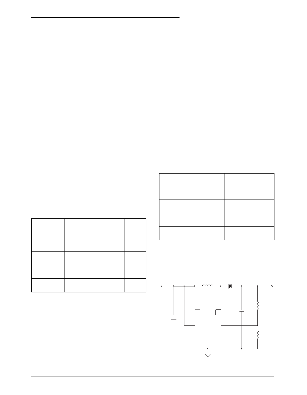
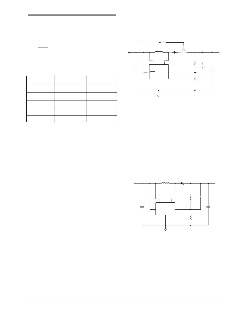
Output Voltage Program
NUMBER VOLTAGE TYPE
The SP4446 can be programmed as voltage source,
the SP4446 requires 2 feedback resistors R1 & R
to control the output voltage. As shown in Fig. 19.
VIN
L1
D1
VOUT
2
Diode Selection
A schottky diode with a low forward drop and fast
switching speed is ideally used here to achieve
high efficiency. In selecting a Schottky diode, the
current rating of the schottky diode should be
larger than the peak inductor current. Moreover,
C1
U1
1
5
S
V
4
W
I
N
SP4446
FBSHDN
D
N
G
2
C2
3
1.22V
R1
R2
the reverse breakdown voltage of the schottky
diode should be larger than the output voltage.
Figure 19. Using SP4446 as Voltage Source
Date: 11/29/04 SP4446 High Output Voltage Boost Regualtor, LCD Bias Regulator © Copyright 2003 Sipex Corporation
4
Page 5
APPLICATION INFORMAMTION: Continued
The formula and table for the resistor selection
are shown below:
V
1
=(
OUT
- 1 ) • R
2
R
1.22
Table 3. Divider Resistor Selection
V
(V) R1 (Ω)R
OUT
(Ω)
2
12 1M 113K
15 1M 88.7K
18 1M 73.2K
20 1M 64.9K
30 1M 42.2K
Layout Consideration
Both the input capacitor and the output capacitor
should be placed as close as possible to the IC.
This can reduce the copper trace resistance which
directly effects the input and output ripples. The
feedback resistor network should be kept close to
the FB pin to minimize copper trace connections
that can inject noise into the system. The ground
connection for the feedback resistor network should
connect directly to the GND pin or to an analog
ground plane that is tied directly to the GND pin.
The inductor and the schottky diode should be
placed as close as possible to the switch pin to
minimize the noise coupling to the other circuits,
especially the feedback network.
Load Disconnect in Shutdown
will be slightly sacrificed because of the saturation voltage and base current of the PNP transistor.
R3
154K
L1
5
V
IN
10uH
U1
SP4446
GND
2
1
SW
FBSHDN
V
IN
C1
4.7uF
34
1.22V
DS
Q1
MMBT2907A
64.9K
R1
1M
R2
C2
47pF
Fig. 20. Load Disconnect in Shutdown
PIN Diode Driver
The SP4446 can be used as PIN diode driver as
shown in Fig. 21. Two Resistors (R1=1MΩ,
R2=42.2KΩ) are used to program the output voltage to be 30V. When input voltage is 3.3V or 5V,
it can supply a maximum current of 3mA and 5mA
to the load.
Murata LQH32CN100K21
3.3V or 5V
3.3V or 5V
Murata LQH32CN100K21
L1 10uH 0.3A
C1
C1
4.7uF
4.7uF
L1 10uH 0.3A
U1
U1
5
V
IN
SP4446
SP4446
SHDN
GND
2
2
V
IN
DS
DS
MBR0530
MBR0530
C2
C2
47pF
47pF
R1
R1
1M
1M
1
1
S
W
34
34
FBSHDN
1.22V
1.22V
R2
R2
42.2K
42.2K
2.2uF
2.2uF
V
30V
30V
OUT
3 to 5 mA
3 to 5 mA
C3
C3
V
OUT
20V
C3
2.2uF
When SP4446 was shut down, the load is still
connected to the input. In applications that require output isolation during shutdown, an external PNP transistor (for example MMBT2907A)
Fig. 21. Pin Diode Driver
can be added as shown in Figure 20. When the
SP4446 is active, the voltage set at the emitter of
the transistor exceeds the input voltage, forcing
the transistor into the saturation region. When
the SP4446 is shut down, the input voltage
exceeds the emitter voltage, thus the transistor
becomes inactive and provides high-impedance
isolation between the input and load. Efficiency
Date: 11/29/04 SP4446 High Output Voltage Boost Regualtor, LCD Bias Regulator © Copyright 2004 Sipex Corporation
5
Page 6
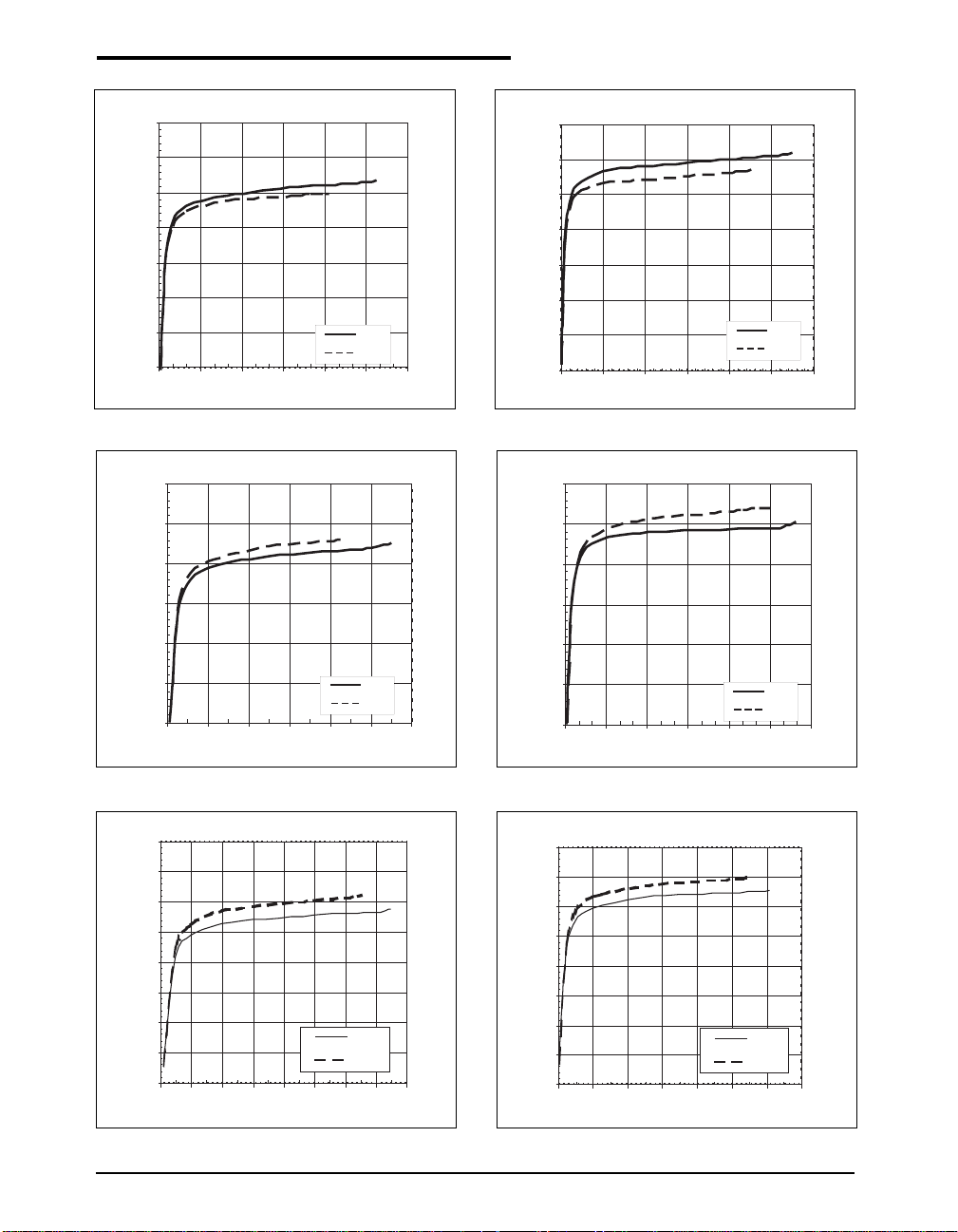
Refer to the typical application circuit, T
= 25°C, unless otherwise specified.
PERFORMANCE CHARACTERISTICS
AMB
85
80
75
70
65
Efficiency (%)
60
55
50
Vin=3.3V;Vout =12V Efficiency
0369121518
Iout (mA)
Figure 1. 12V Output Efficiency (V
80
75
70
65
Efficiency (%)
60
Vin=3.3V;Vout =15V Efficiency
=3.3V)
IN
10 uH
22 uH
85
80
75
70
65
Efficiency (%)
60
55
50
051015 20 25 30
Vin=5.0V;Vout =12V Efficiency
Iout (mA)
Figure 2. 12V Output Efficiency (VIN=5V)
80
75
70
65
Efficiency (%)
60
Vin=5.0V;Vout =15V Efficiency
10 uH
22 uH
55
50
024681012
Iout (mA)
Figure 3. 15V Output Efficiency (VIN=3.3V)
80
75
70
65
60
Efficiency (%)
55
50
45
40
0.0 1.0 2.0 3.0 4.0 5.0 6.0 7.0 8.0
Vin=3.3V; Vout = 18V Efficiency
10 uH
22 uH
Iout (mA)
Figure 5. 18V Output Efficiency (VIN=3.3V)
10 uH
22 uH
55
50
0369121518
Iout (mA)
Figure 4. 15V Output Efficiency (VIN=5V)
80
75
70
65
60
Efficiency (%)
55
50
45
40
0.0 2.0 4.0 6.0 8.0 10.0 12.0 14.0
Vin=5.0V; Vout = 18V Efficiency
10 uH
22 uH
Iout (mA)
Figure 6. 18V Output Efficiency (VIN=5V)
10 uH
22 uH
Date: 11/29/04 SP4446 High Output Voltage Boost Regualtor, LCD Bias Regulator © Copyright 2003 Sipex Corporation
6
Page 7
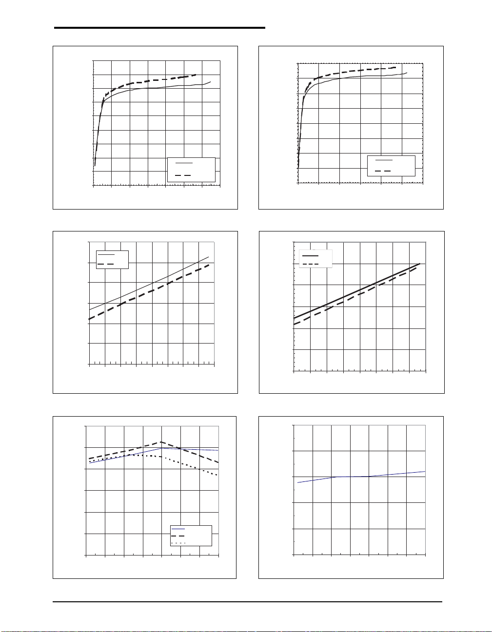
Refer to the typical application circuit, T
= 25°C, unless otherwise specified.
PERFORMANCE CHARACTERISTICS
AMB
75
70
65
60
55
50
Efficiency (%)
45
40
35
30
01234567
Vin=3.3V;Vout = 20V Efficiency
Iout (mA)
Figure 7. 20V Output Efficiency (VIN=3.3V)
12
10
8
6
4
Maximum Output Current (mA)
2
0
2.7 3 3.3 3.6 3.9 4.2 4.5 4.8 5.1
10uH
22uH
Input Voltage (V)
10 uH
22 uH
75
70
65
60
55
Efficiency (%)
50
45
40
35
024681012
Vin=5V;Vout = 20V Efficiency
Iout (mA)
Figure 8. 20V Output Efficiency (VIN=5V)
6
5
4
3
2
Maximum Output Current (mA)
1
0
10uH
22uH
2.7 3 3.3 3.6 3.9 4.2 4.5 4.8 5.1
Input Voltage (V)
10 uH
22 uH
Figure 9. Maximum Output Current vs. VIN (V
30
25
20
15
10
Quiescent Current (uA)
5
0
12345678
Input Voltage (V)
Figure 11. Quiescent Current IQ vs. V
Tamb=-40°C
Tamb=25°C
Tamb=85°C
IN
OUT
=20V)
Figure 10. Maximum Output Current vs. VIN (V
10
8
6
4
Shutdown Pin Current (uA)
2
0
12345678
Figure 12. Shutdown Pin Current vs. V
Input Voltage (V)
IN
OUT
=30V)
Date: 11/29/04 SP4446 High Output Voltage Boost Regualtor, LCD Bias Regulator © Copyright 2004 Sipex Corporation
7
Page 8
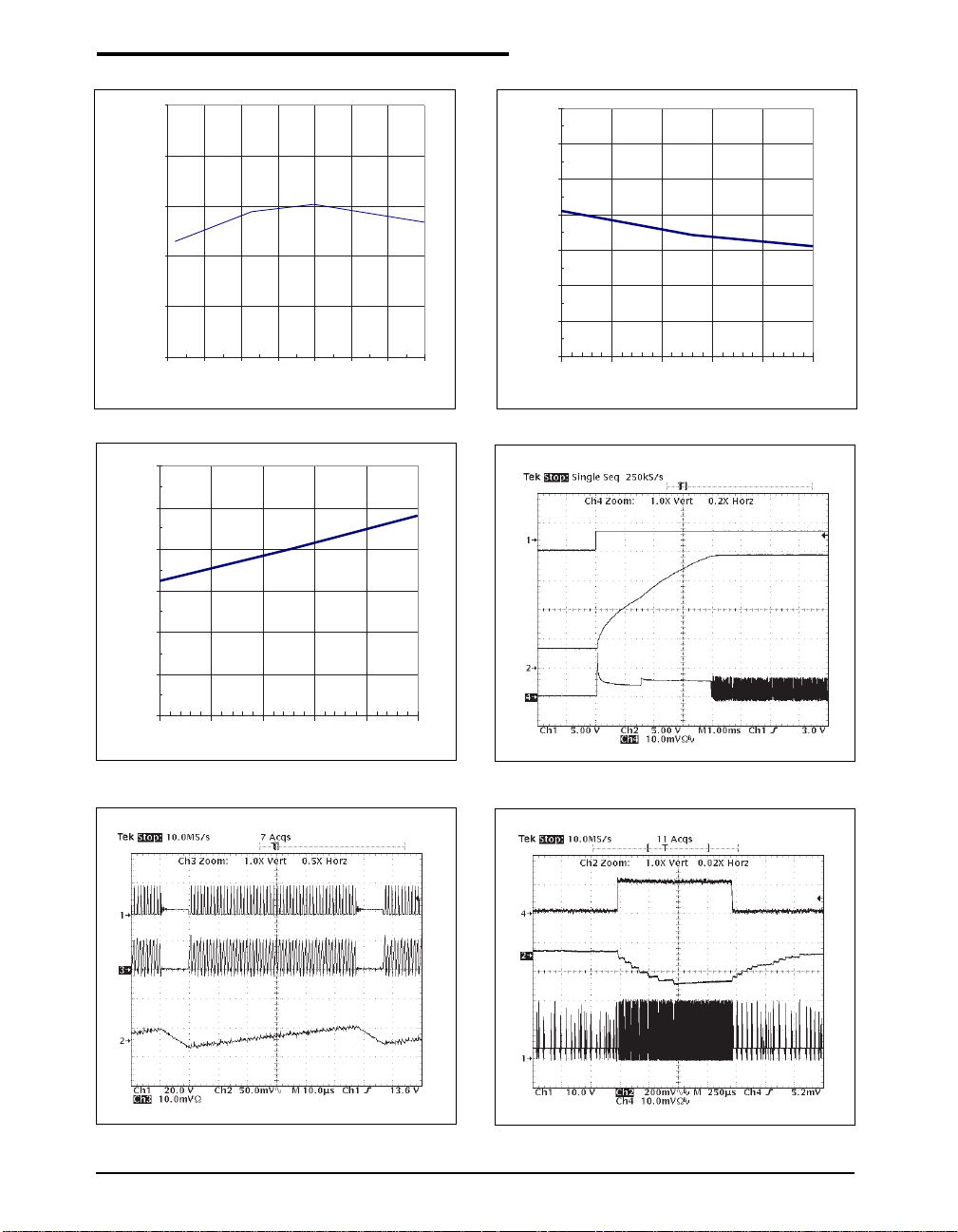
Refer to the typical application circuit, T
= 25°C, unless otherwise specified.
PERFORMANCE CHARACTERISTICS
AMB
250
200
150
100
Ipk Current Limit (mA)
50
0
12345678
Input Voltage (V)
Figure 13. IPK Current Limit vs. V
60
50
40
30
20
Switch Saturation Voltage (mV)
10
1.25
1.24
1.23
1.22
1.21
Feedback Voltage (V)
1.20
1.19
1.18
-40 -15 10 35 60 85
IN
Figure 14. Feedback Voltage vs. Temperature
V
IN
V
OUT
Temperature (C)
I
(100mA/DIV)
OUT
=2mA)
IN
=20V,
OUT
I
(5mA/DIV)
OUT
V
(AC)
OUT
V
SW
=20V,
OUT
0
-40 -15 10 35 60 85
Figure 15. Switch Saturation Voltage V
Temperature (C)
CESAT
vs.
Temperature (ISW=50mA)
V
SW
I
(0.1A/DIV)
L
V
(AC)
OUT
Figure 17. Typical Switching Waveforms (VIN=3.3V,
V
OUT
=20V, I
OUT
=5mA)
Figure 16. Startup Waveform (VIN=3.3V, V
I
Figure 18. Load Step Transient (VIN=3.3V, V
1O=100µA∼5mA)
Date: 11/29/04 SP4446 High Output Voltage Boost Regualtor, LCD Bias Regulator © Copyright 2003 Sipex Corporation
8
Page 9
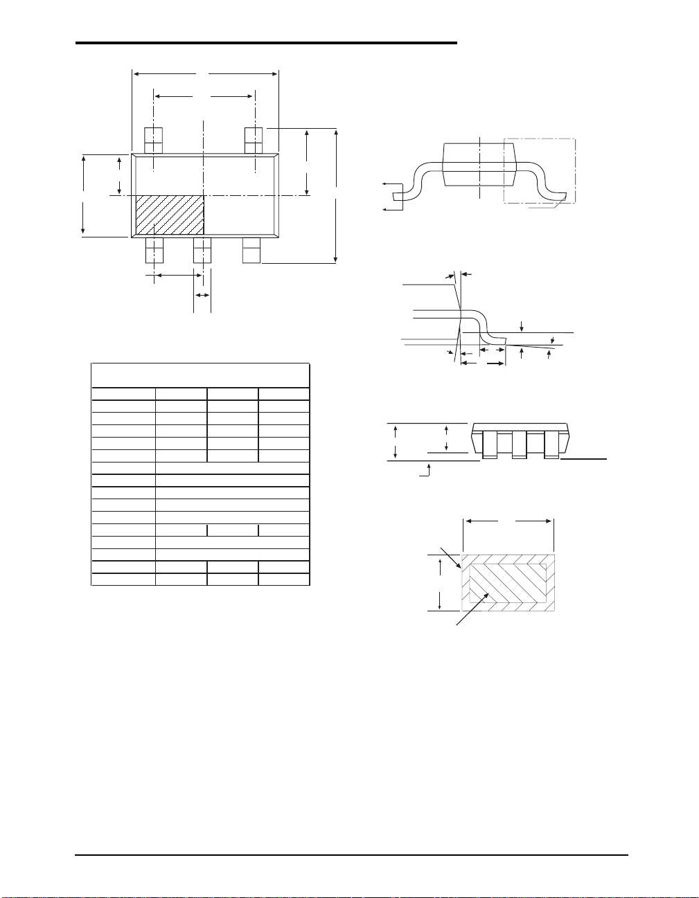
PACKAGE: 5 PIN SOT-23
D
e1
N
E1/2
E1
1
e
N/2
+1
N/22
b
5 Pin SOT-23 JEDEC MO-178 (AA) Variation
SYMBOL
MIN NOM MAX
A--1.45
A1 0 - 0.15
A2 0.9 1.15 1.3
b0.3-0.5
c0.08-0.22
D
E
E1
e
e1
2.90 BSC
2.80 BSC
1.60 BSC
0.95 BSC
1.90 BSC
L0.30.45 0.6
L1
L2
0.60 REF
0.25 BSC
Ø0º4º8º
ø5º10º 15º
Note: Dimensions in (mm)
E/2
E
B
B
SEE VIEW C
VIEW A-A
Ø
Gauge Plane
Seating Plane
Ø
L1
L
L
Ø
VIEW C
A
WITH PLATING
A2
Seating Plane
A1
SIDE VIEW
b
c
BASE METAL
Date: 11/29/04 SP4446 High Output Voltage Boost Regualtor, LCD Bias Regulator © Copyright 2004 Sipex Corporation
SECTION B-B
9
Page 10
ORDERING INFORMATION
Part Number Operating Temperature Range Package Type
SP4446EK .................................................. -40°C to +85°C ........................................................ 5 Pin SOT-23
SP4446EK/TR ............................................ -40°C to +85°C ........................................................5 Pin SOT-23
Available in lead free packaging. To order add "-L" suffix to part number.
Example: SP4446EK/TR = standard; SP4446EK-L/TR = lead free
/TR = Tape and Reel
Pack quantity is 2,500 for SOT-23.
CLICK HERE TO ORDER SAMPLES
Corporation
ANALOG EXCELLENCE
Sipex Corporation
Headquarters and
Sales Office
233 South Hillview Drive
Milpitas, CA 95035
TEL: (408) 934-7500
FAX: (408) 935-7600
Sipex Corporation reserves the right to make changes to any products described herein. Sipex does not assume any liability arising out of the
application or use of any product or circuit described herein; neither does it convey any license under its patent rights nor the rights of others.
Date: 11/29/04 SP4446 High Output Voltage Boost Regualtor, LCD Bias Regulator © Copyright 2003 Sipex Corporation
10
 Loading...