

Page 1
查询SP1481E供应商
®
PRELIMINAR Y
±15kV Enhanced Low Power Half-Duple x
■ +5V supply
■ Low Power BiCMOS
■ Driver/Receiver Enable for Multi-Drop
configurations
■ Low Power Shutdown Mode (1µA
Typical)
■ Available in 8 Pin NSOIC or PDIP
packages (Standard 75176 pinout)
■ Enhanced ESD Specifications:
+15KV Human Body Model
+15KV IEC1000-4-2 Air Discharge
+8KV IEC1000-4-2 Contact Discharge
SP1481E
RS-485 T ransceivers
1
RO
RE
DE
DI
2
3
4
SP1481E
8 Pin - nSOIC
V
8
CC
B
7
A
6
5
GND
DESCRIPTION
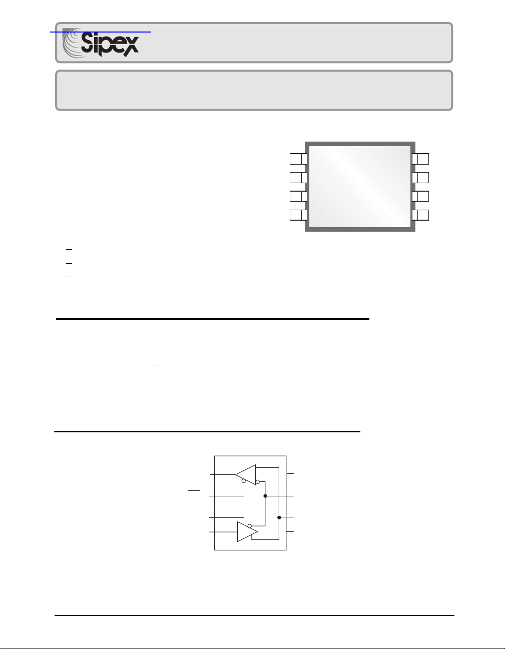
The SP1481E is a half-duplex transceiver that meets the specifications of RS-485 and RS422 serial protocols with enhanced ESD performance. The ESD tolerance has been improved
on this device to over +15KV for both Human Body Model and IEC1000-4-2 Air Discharge
Method. This device is pin-to-pin compatible with Sipex's SP485 and SP481 devices as well
as popular industry standards. As with the original version, the SP1481E features Sipex's
BiCMOS design allowing low power operation without sacrificing performance. The SP1481E
meets the requirements of the RS-485 and RS-422 protocols up to 20Mbps under load.
BLOCK DIAGRAM
RO 1
RE 2
DE 3
DI 4
R
D
SP1481E
8 Vcc
7 B
6 A
5 GND
Rev:B Date: 02/26/04 SP1481E Low Power Half-Duplex RS485 Transceivers © Copyright 2004 Sipex Corporation
1
Page 2
ABSOLUTE MAXIMUM RATINGS
These are stress ratings only and functional operation of the device at
these ratings or any other above those indicated in the operation sections
of the specifications below is not implied. Exposure to absolute maximum
rating conditions for extended periods of time may affect reliability.
VCC............................................................................................................+7V
Input Voltages
Logic........................................................-0.3V to (VCC+0.5V)
Drivers..................................................-0.3V to (VCC+0.5V)
Receivers................................................................. ±15V
Output Voltages
Storage Temperature.......................................................-65˚C to +150˚C
Power Dissipation per Package
8-pin NSOIC (derate 6.60mW/
8-pin PDIP (derate 11.8mW/
Logic........................................................-0.3V to (VCC+0.5V)
Drivers...................................................................... ±15V
Receivers............................................-0.3V to (VCC+0.5V)
o
C above +70oC)...........................550mW
o
C above +70oC)............................1000mW
ELECTRICAL CHARACTERISTICS
T
to T
and VCC = 5V ± 5% unless otherwise noted.
MIN
MAX
PARAMETERS MIN. TYP. MAX. UNITS CONDITIONS
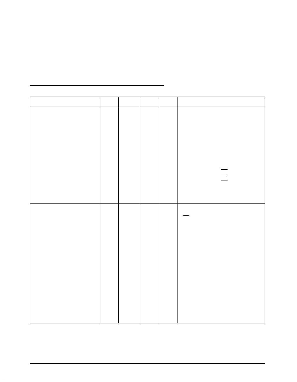
SP1481E DRIVER
DC Characteristics
Differential Output Voltage 3.5 V
Differential Output Voltage 2 V
Differential Output Voltage 1.5 V
Change in Magnitude of Driver
Differential Output Voltage for
Complimentary States 0.2 Volts R = 27Ω or R = 50Ω;
Driver Common-Mode
Output Voltage 3 Volts R = 27Ω or R = 50Ω;
Input High Voltage 2.0 Volts Applies to DE, DI, RE
Input Low Voltage 0.8 Volts Applies to DE, DI, RE
Input Current ±10 µA Applies to DE, DI, RE
Driver Short-Circuit Current
V
= HIGH ±250 mA -7V ≤ VO ≤ +12V
OUT
V
= LOW ±250 mA -7V ≤ VO ≤ +12V
OUT
SP1481E DRIVER
AC Characteristics
Maximum Data Rate 20 Mbps RE = 5V, DE = 5V; R
Driver Input to Output 10 30 40 ns t
10 ns t
Driver Skew 3 ns
Driver Rise or Fall Time 8 20 ns From 10% to 90%; R
Driver Enable to Output High 40 70 ns CL = 100pF;
Driver Enable to Output Low 40 70 ns CL = 100pF;
Driver Disable Time from Low 40 70 ns CL = 100pF;
Driver Disable Time from High 40 70 ns CL = 100pF;
closed
Volts Unloaded; R = ∞ ;
CC
Volts with load; R = 50Ω; (RS-422);
CC
Volts with load; R = 27Ω; (RS-485);
CC
see Figure 1
CL1 = CL2 = 100pF
; R
PLH
see Figures 3 and 5
= 54Ω, CL1 = CL2 = 100pF;
DIFF
; R
PHL
= 54Ω, C
DIFF
see Figures 3 and 5,
t
= | t
SKEW
CL1 = C
DPLH
= 100pF;
L2
closed
closed
closed
see Figures 4 & 6;
see Figure 1
see Figure 1
see Figure 1
see Figure 1
= 54Ω,
DIFF
= CL2 = 100pF;
LI
- t
|
DPHL
= 54Ω,
DIFF
s
ee Figures 3 &
see Figures 4 & 6;
see Figures 4 & 6;
see Figures 4 & 6;
6
S
2
S
1
S
1
S
2
Rev:B Date: 02/26/04 SP1481E Low Power Half-Duplex RS485 Transceivers © Copyright 2004 Sipex Corporation
2
Page 3
T
to T
and VCC = 5V ± 5% unless otherwise noted.
MIN
MAX
SPECIFICATIONS (continued)
PARAMETERS MIN. TYP. MAX. UNITS CONDITIONS
SP148
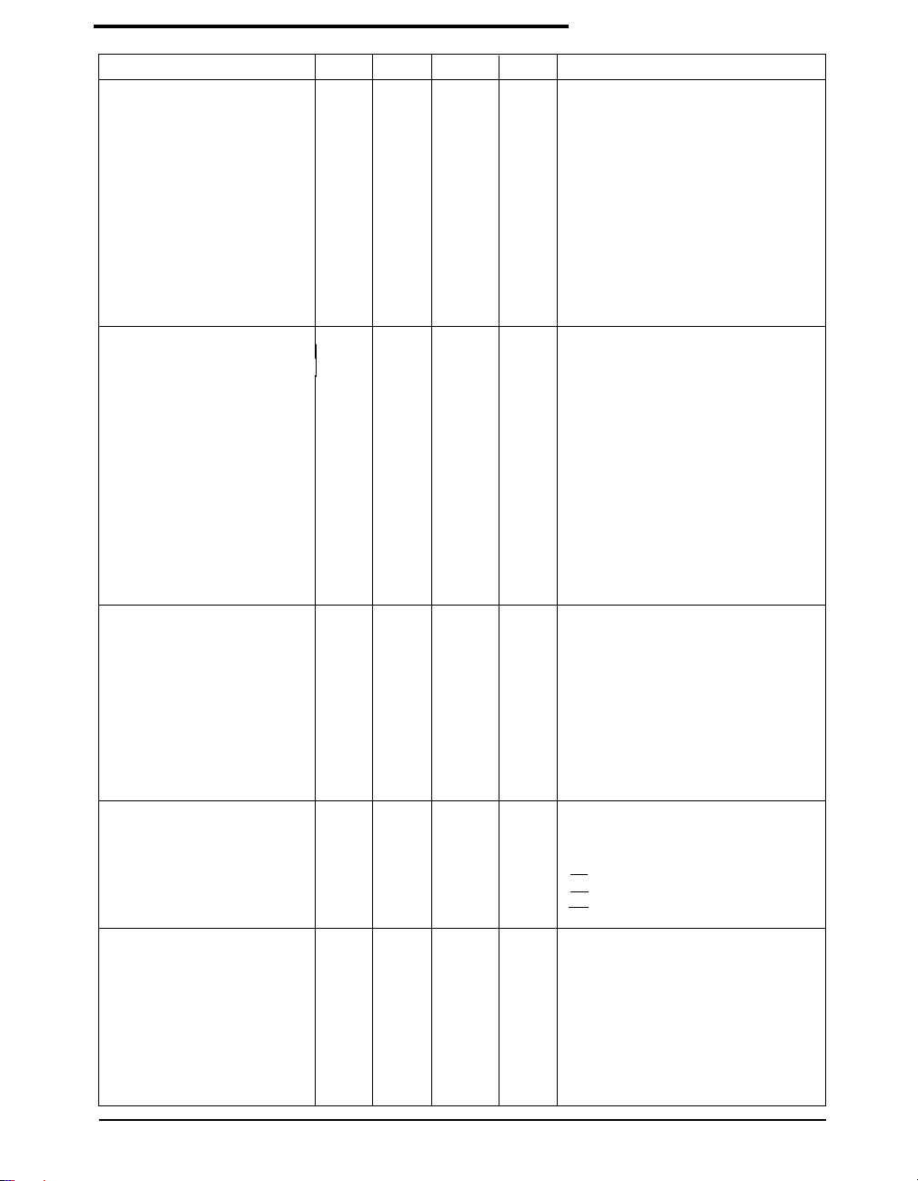
1E RECEIVER
DC Characteristics
Differential Input Threshold -0.2 +0.2 Volts -7V ≤ V
Differential Input Threshold -0.4 +0.4 Volts -7V ≤ V
(SP1485EMN ONLY)
Input Hysteresis 20 mV V
Output Voltage High 3.5 Volts I
Output Voltage Low 0.4 Volts I
Three-State (High Impedance)
CM
= -4mA, VID = +200mV
O
= +4mA, VID = -200mV
O
Output Current ±1 µA 0.4V ≤ V
Input Resistance 12 15 kΩ -7V ≤ V
Input Current (A, B); VIN = 12V +1.0 mA DE = 0V, VCC = 0V or 5.25V, VIN = 12V
Input Current (A, B); V
Short-Circuit Current 7 95 mA 0V ≤ V
= -7V -0.8 mA DE = 0V, VCC = 0V or 5.25V, VIN = -7V
IN
≤ +12V
CM
≤ +12V
CM
= 0V
≤ 2.4V; RE = 5V
O
≤ +12V
CM
≤ V
O
CC
SP1481E RECEIVER
AC Characteristics
Maximum Data Rate 20 Mbps RE = 0V, DE = 0V
Receiver Input to Output 15 40 50 ns t
15 ns t
Diff. Receiver Skew It
I510nsR
PLH-tPHL
; R
DIFF
= 100pF;
L2
; R
DIFF
= 54Ω; C
= 54Ω,
= 54Ω, C
PLH
CL1 = C
PHL
DIFF
Figures 3 & 7
Figures 3 & 7
LI
= C
L1
L2
= CL2 = 100pF
= 100pF;
Receiver Enable to
Output Low 45 70 ns CRL = 15pF;
Figures 2 & 8;
S1 closed
Receiver Enable to
Output High 45 70 ns CRL = 15pF;
Receiver Disable from Low 45 70 ns CRL = 15pF;
Receiver Disable from High 45 70 ns CRL = 15pF;
Figures 2 & 8;
Figures 2 & 8;
Figures 2 & 8;
S2 closed
S1 closed
S2 closed
SP1481E
Shutdown Timing
Time to Shutdown 50 200 600 ns RE = 5V, DE = 0V
Driver Enable from Shutdown
to Output High 40 100 ns CL = 100pF;
See Figures 4 & 6;
S2 closed
Driver Enable from Shutdown
to Output Low 40 100 ns CL = 100pF;
See Figures 4 & 6;
S1 closed
Receiver Enable from
Shutdown to Output High 300 1000 ns CL = 15pF;
See Figures 2 & 8;
S2 closed
Receiver Enable from
Shutdown to Output Low 300 1000 ns CL = 15pF;
See Figures 2 & 8;
S1 closed
POWER REQUIREMENTS
Supply Voltage +4.75 +5.25 Volts
Supply Current
SP1481E
No Load 900 µA RE, DI = 0V or VCC; DE = V
600 µA RE = 0V, DI = 0V or 5V; DE = 0V
SHUTDOWN 10 µA
RE = 5V, DE = 0V
CC
ENVIRONMENTAL
AND MECHANICAL
Operating Temperature
Commercial (_C_) 0 +70 °C
Industrial (_E_) -40 +85 °C
(_M_) -40 +125 °C
Storage Temperature -65 +150 °C
Package
Plastic DIP (_P)
NSOIC (_N)
Rev:B Date: 02/26/04 SP1481E Low Power Half-Duplex RS485 Transceivers © Copyright 2004 Sipex Corporation
3
Page 4
RO 1
RE 2
DE 3
DI 4
R
D
SP485
Top View
SP1485E
Pinout (Top View)
8 V
CC
7 B
6 A
5 GND
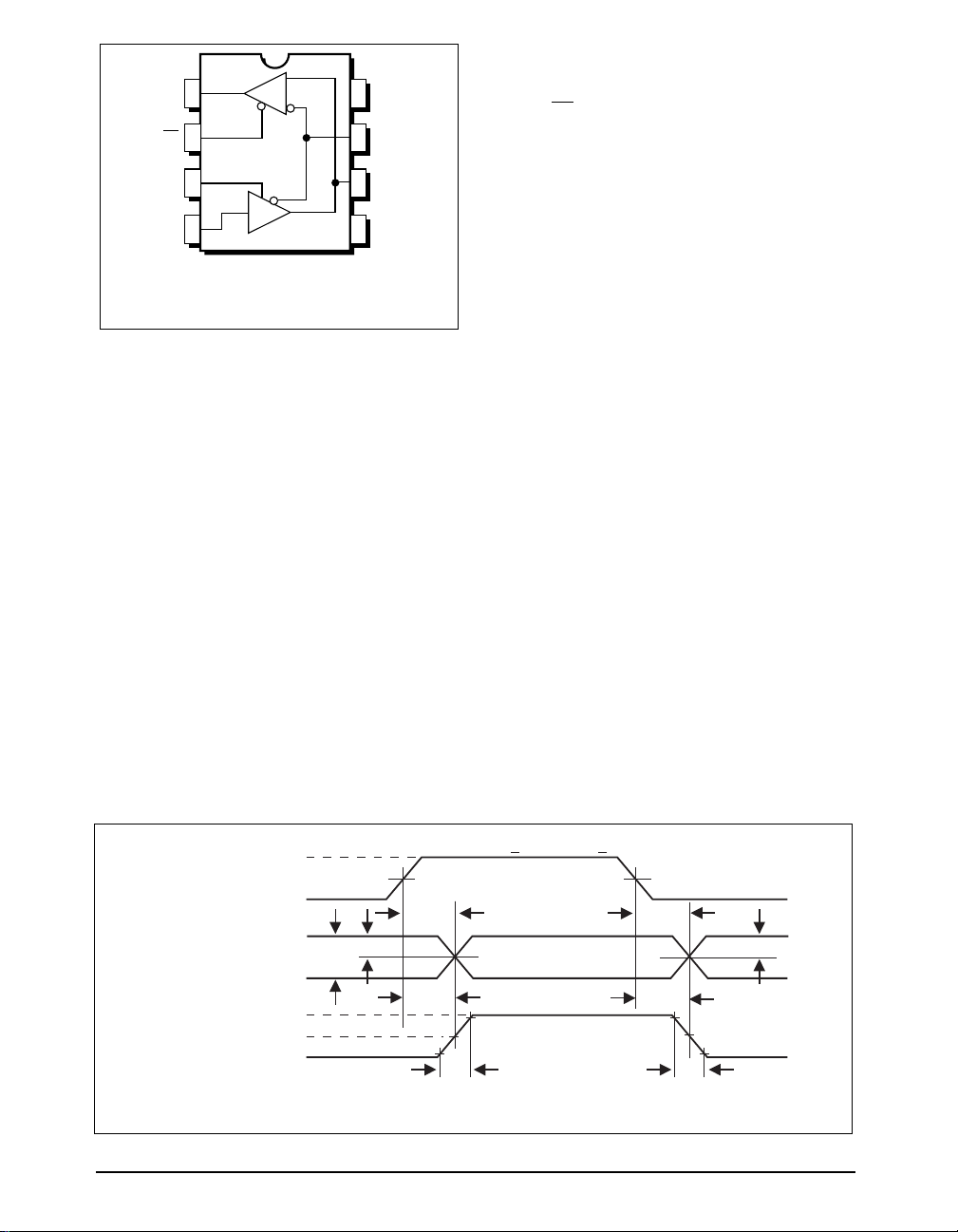
PIN FUNCTION
Pin 1 – RO – Receiver Output.
Pin 2 – RE – Receiver Output Enable Active LOW.
Pin 3 – DE – Driver Output Enable Active HIGH.
Pin 4 – DI – Driver Input.
Pin 5 – GND – Ground Connection.
Pin 6 – A – Driver Output/Receiver Input
Non-inverting.
Pin 7 – B – Driver Output/Receiver Input Inverting.
Pin 8 – Vcc – Positive Supply 4.75V<Vcc< 5.25V.
+3V
f = 1MHz; tR < 1.0ns; tF < 1.0ns
DI
0V
DRIVER
OUTPUT
DIFFERENTIAL
OUTPUT
V
– V
A
t
SKEW = | tDPLH - tDPHL
Figure 5. Driver Propagation Delays
Rev:B Date: 02/26/04 SP1481E Low Power Half-Duplex RS485 Transceivers © Copyright 2004 Sipex Corporation
B
A
+
V
O
0V
–
V
O
B
|
1/2V
V
O
1.5V 1.5V
t
PLH
O
t
DPLH
t
R
t
PHL
t
DPHL
t
F
1/2V
O
4
Page 5
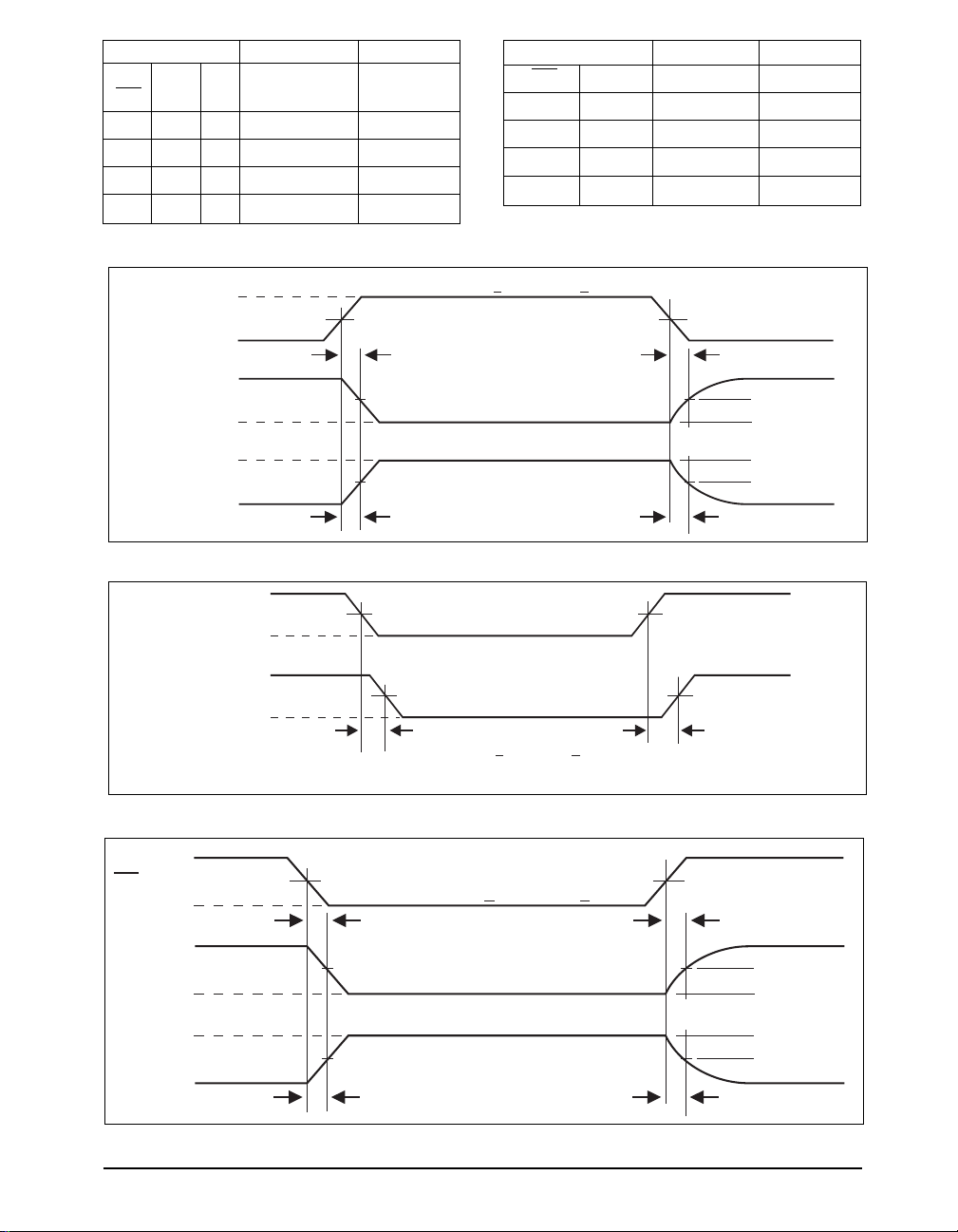
INPUTS OUTPUTS
LINE
RE DE DI CONDITION B A
X11No Fault 0 1
X10No Fault 1 0
X0X X ZZ
X1X Fault Z Z
Table 1. Transmit Function Truth Table
INPUTS OUTPUTS
RE DE A - B R
00 +0.2V 1
00 -0.2V 0
00Inputs Open 1
10 X Z
Table 2. Receive Function Truth Table
+3V
DE
1.5V 1.5V
0V
5V
A, B
V
OL
V
OH
A, B
0V
Figure 6. Driver Enable and Disable Times
+
V
0D2
A – B
t
SKEW = | tPHL - tPLH
Figure 7. Receiver Propagation Delays
–
V
0D2
V
OH
R
V
OL
t
PHL
|
f = 1MHz; tR < 1.0ns; tF < 1.0ns
t
ZL
2.3V
2.3V
0V 0V
Output normally LOW
Output normally HIGH
t
ZH
INPUT
1.5V 1.5V
f = 1MHz; tR < 1.0ns; tF < 1.0ns
OUTPUT
t
PLH
0.5V
0.5V
t
LZ
t
HZ
+3V
RE
0V
1.5V 1.5V
f = 1MHz; tR < 1.0ns; tF < 1.0ns
t
ZL
t
LZ
5V
R
V
IL
V
IH
R
0V
Figure 8. Receiver Enable and Disable Times
Rev:B Date: 02/26/04 SP1481E Low Power Half-Duplex RS485 Transceivers © Copyright 2004 Sipex Corporation
1.5V
1.5V
Output normally LOW
Output normally HIGH
t
ZH
0.5V
0.5V
t
HZ
5
Page 6

DESCRIPTION
The SP1481E is half-duplex differential transceivers that meet the requirements of RS-485
and RS-422. Fabricated with a Sipex proprietary
BiCMOS process, this product requires a fraction of the power of older bipolar designs.
The RS-485 standard is ideal for multi-drop
applications and for long-distance interfaces.
RS-485 allows up to 32 drivers and 32 receivers
to be connected to a data bus, making it an ideal
choice for multi-drop applications. Since the
cabling can be as long as 4,000 feet, RS-485
transceivers are equipped with a wide (-7V to
+12V) common mode range to accommodate
ground potential differences. Because RS-485 is
a differential interface, data is virtually immune
to noise in the transmission line.
Drivers
The driver outputs of the SP1481E are differential outputs meeting the RS-485 and RS-422
standards. The typical voltage output swing with
no load will be 0 Volts to +5 Volts. With worst
case loading of 54Ω across the differential outputs, the drivers can maintain greater than 1.5V
voltage levels. The drivers of the SP1481E have
an enable control line which is active HIGH. A
logic HIGH on DE (pin 3) will enable the differential driver outputs. A logic LOW on DE (pin
3) will tri-state the driver outputs.
The transmitters of the SP1481E will operate up
to at least 20Mbps.
Receivers
The SP1481E receivers have differential inputs
with an input sensitivity as low as ±200mV.
Input impedance of the receivers is typically
15kΩ (12kΩ minimum). A wide common mode
range of -7V to +12V allows for large ground
potential differences between systems. The receivers of the SP1485E have a tri-state enable
control pin. A logic LOW on RE (pin 2) will
enable the receiver, a logic HIGH on RE (pin 2)
will disable the receiver.
The receiver for the SP1481E will operate up to
at least 20Mbps. The receiver for each of the two
devices is equipped with the
fail-safe feature. Fail-safe guarantees that the
receiver output will be in a HIGH state when
the input is left unconnected.
SHUTDOWN MODE
The SP1481E is equipped with a Shutdown
mode. To enter the Shutdown state, both the
driver and receiver must be disabled simultaneously.
A logic LOW on DE (pin 3) and a logic HIGH on
RE (pin 2) will put the SP1481E into Shutdown
mode. In Shutdown, supply current will drop to
typically 1µA.
ESD TOLERANCE
The SP1481E incorporates ruggedized ESD
cells on all driver output and receiver input pins.
The ESD structure is improved over our previous family for more rugged applications and
environments sensitive to electro-static discharges and associated transients. The improved
ESD tolerance is at least ±15kV without damage
or latch-up.
There are different methods of ESD testing
applied:
a) MIL-STD-883, Method 3015.7
b) IEC1000-4-2 Air-Discharge
c) IEC1000-4-2 Direct Contact
The Human Body Model has been the generally
accepted ESD testing method for semiconductors.
This method is also specified in MIL-STD-883,
Method 3015.7 for ESD testing. The premise of
this ESD test is to simulate the human body’s
potential to store electro-static energy and
discharge it to an integrated circuit. The
simulation is performed by using a test model as
shown in Figure 7. This method will test the
IC’s capability to withstand an ESD transient
during normal handling such as in manufacturing
areas where the ICs tend to be handled frequently.
The IEC-1000-4-2, formerly IEC801-2, is
generally used for testing ESD on equipment and
systems. For system manufacturers, they must
guarantee a certain amount of ESD protection
since the system itself is exposed to the outside
environment and human presence. The premise
with IEC1000-4-2 is that the system is required
Rev:B Date: 02/26/04 SP1481E Low Power Half-Duplex RS485 Transceivers © Copyright 2004 Sipex Corporation
6
Page 7
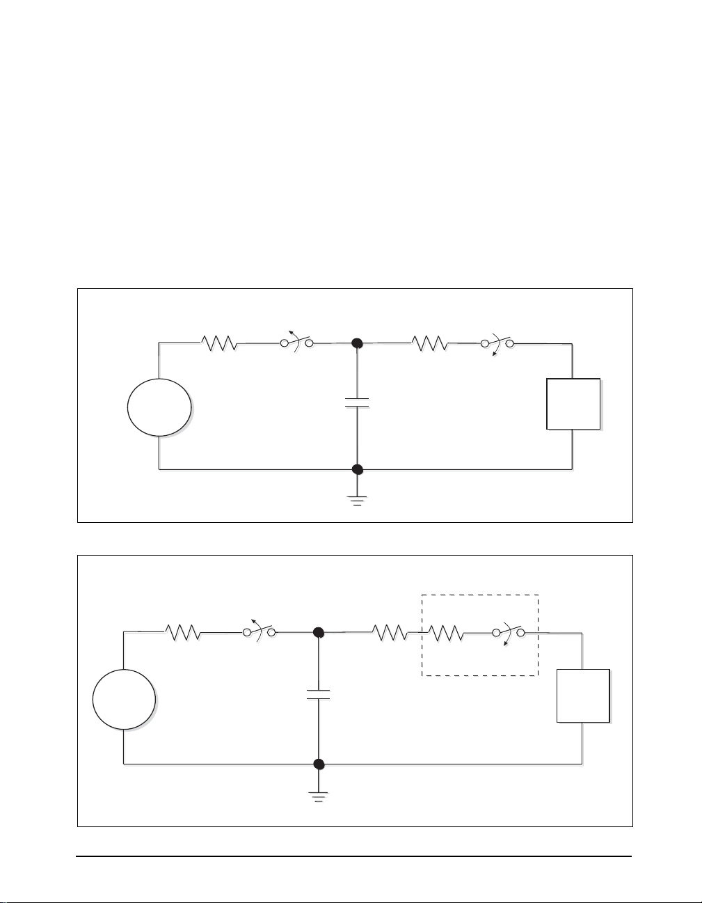
to withstand an amount of static electricity when
ESD is applied to points and surfaces of the
equipment that are accessible to personnel during
normal usage. The transceiver IC receives most
of the ESD current when the ESD source is
applied to the connector pins. The test circuit for
IEC1000-4-2 is shown on Figure 8. There are
two methods within IEC1000-4-2, the Air
Discharge method and the Contact Discharge
method.
R
R
C
C
R
R
S
S
SW1
SW1
DC Power
Source
Figure 7. ESD Test Circuit for Human Body Model
R
R
C
C
SW1
SW1
DC Power
Source
SW2
SW2
C
C
S
S
Contact-Discharge Module
Contact-Discharge Module
R
R
S
S
C
C
S
S
R
R
V
V
SW2
SW2
Device
Under
Test
Device
Under
Test
and RV add up to 330Ω for IEC1000-4-2.
R
RS and RV add up to 330Ω for IEC1000-4-2.
S
Figure 8. ESD Test Circuit for IEC1000-4-2
Rev:B Date: 02/26/04 SP1481E Low Power Half-Duplex RS485 Transceivers © Copyright 2004 Sipex Corporation
7
Page 8
With the Air Discharge Method, an ESD voltage
is applied to the equipment under test (EUT)
through air. This simulates an electrically charged
person ready to connect a cable onto the rear of
the system only to find an unpleasant zap just
before the person touches the back panel. The
high energy potential on the person discharges
through an arcing path to the rear panel of the
system before he or she even touches the system.
This energy, whether discharged directly or
through air, is predominantly a function of the
discharge current rather than the discharge
voltage. Variables with an air discharge such as
approach speed of the object carrying the ESD
potential to the system and humidity will tend to
change the discharge current. For example, the
rise time of the discharge current varies with the
approach speed.
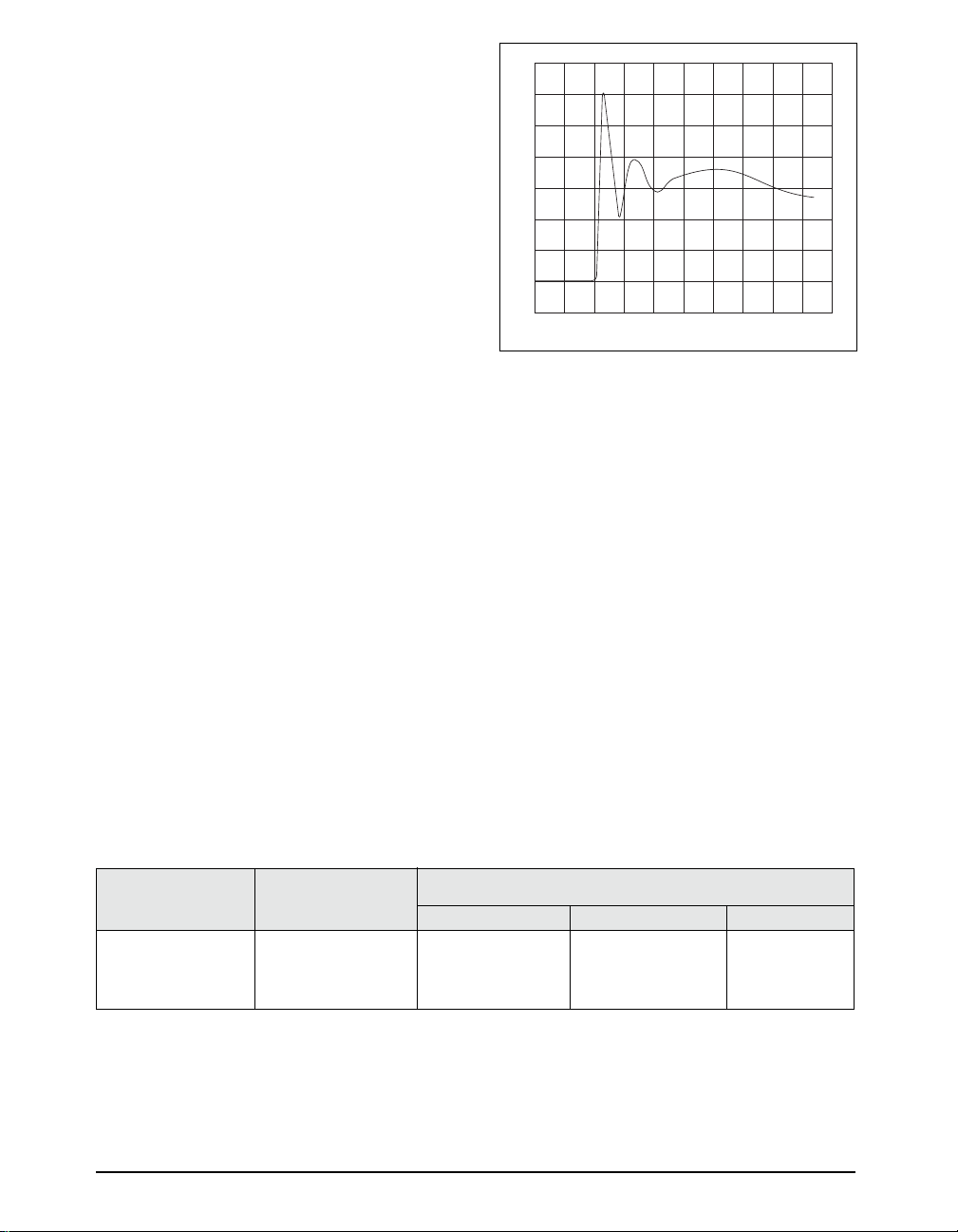
i ➙
30A
15A
0A
t=0ns t=30ns
t ➙
Figure 9. ESD Test Waveform for IEC1000-4-2
The Contact Discharge Method applies the ESD
current directly to the EUT. This method was
devised to reduce the unpredictability of the
ESD arc. The discharge current rise time is
constant since the energy is directly transferred
voltage stored in the capacitor is then applied
through RS, the current limiting resistor, onto the
device under test (DUT). In ESD tests, the SW2
switch is pulsed so that the device under test
receives a duration of voltage.
without the air-gap arc. In situations such as
hand held systems, the ESD charge can be directly
discharged to the equipment from a person already
holding the equipment. The current is transferred
on to the keypad or the serial port of the equipment
directly and then travels through the PCB and finally
For the Human Body Model, the current limiting
resistor (RS) and the source capacitor (CS) are
1.5kΩ an 100pF, respectively. For IEC-1000-4-
2, the current limiting resistor (RS) and the source
capacitor (CS) are 330Ω an 150pF, respectively.
to the IC.
The higher CS value and lower RS value in the
The circuit model in Figures 7 and 8 represent
the typical ESD testing circuit used for all three
methods. The CS is initially charged with the DC
power supply when the first switch (SW1) is on.
Now that the capacitor is charged, the second
switch (SW2) is on while SW1 switches off. The
SP1481E,
HUMAN BODY IEC1000-4-2
SP1485E
MODEL Air Discharge Direct Contact Level
FAMILY
Driver Outputs ±15kV ±15kV ±8kV 4
Receiver Inputs ±15kV ±15kV ±8kV 4
IEC1000-4-2 model are more stringent than the
Human Body Model. The larger storage capacitor
injects a higher voltage to the test point when
SW2 is switched on. The lower current limiting
resistor increases the current charge onto the test
point.
Rev:B Date: 02/26/04 SP1481E Low Power Half-Duplex RS485 Transceivers © Copyright 2004 Sipex Corporation
8
Page 9
D1 = 0.005" min.
(0.127 min.)
D
e = 0.100 BSC
(2.540 BSC)
B1
B
ALTERNATE
END PINS
(BOTH ENDS)
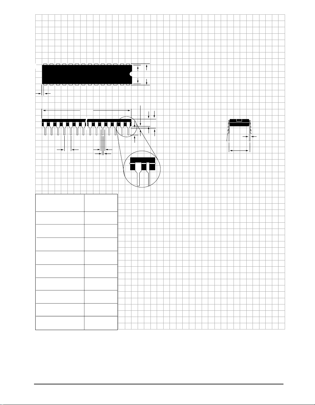
PACKAGE: PLASTIC
DUAL–IN–LINE
(NARROW)
E1
E
A1 = 0.015" min.
(0.381min.)
A = 0.210" max.
(5.334 max).
A2
L
C
Ø
eA = 0.300 BSC
(7.620 BSC)
DIMENSIONS (Inches)
Minimum/Maximum
(mm)
A2
B
B1
C
D
E
E1
L
Ø
8–PIN
0.115/0.195
(2.921/4.953)
0.014/0.022
(0.356/0.559)
0.045/0.070
(1.143/1.778)
0.008/0.014
(0.203/0.356)
0.355/0.400
(9.017/10.160)
0.300/0.325
(7.620/8.255)
0.240/0.280
(6.096/7.112)
0.115/0.150
(2.921/3.810)
0°/ 15°
(0°/15°)
Rev:B Date: 02/26/04 SP1481E Low Power Half-Duplex RS485 Transceivers © Copyright 2004 Sipex Corporation
9
Page 10
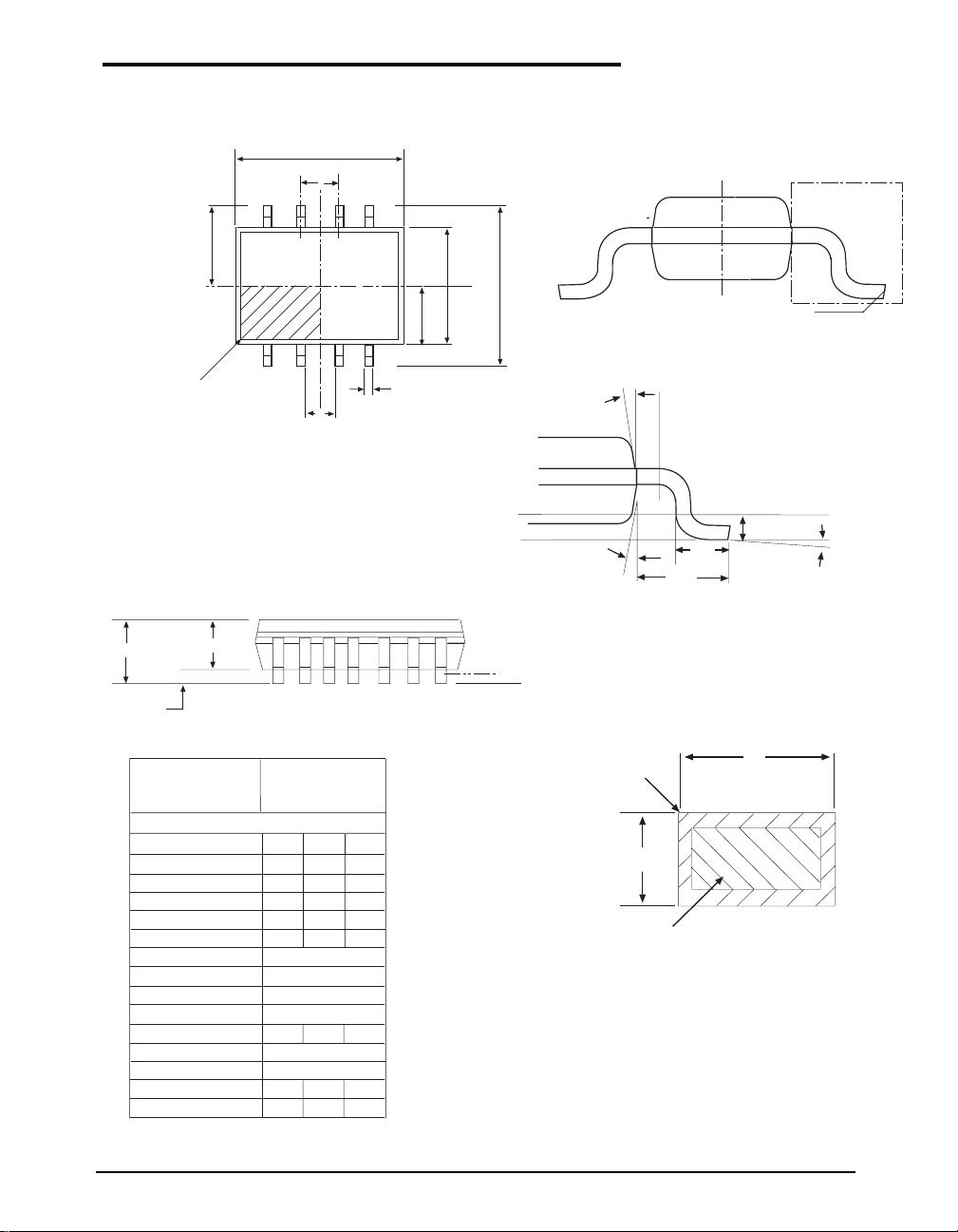
PACKAGE: 8 PIN NSOIC
D
e
E/2
E1
E
INDEX AREA
(D/2 X E1/2)
1
TOP VIEW
A
Minimum/Maximum
A2
A1
DIMENSIONS
(mm)
COMMON HEIGHT DIMENSION
SYMBOL MIN NOM MAX
A
A1
A2
b
c
1.35
0.10
1.25
0.31
0.17 0.25
D
E
E1
e
L
0.40
L1
L2
Ø
Ø1
0º
5º
A
SIDE VIEW
8 Pin NSOIC
(JEDEC MS-012,
AA - VARIATION)
1.75
-
- 0.25
-
1.65
-
0.51
-
4.90 BSC
6.00 BSC
3.90 BSC
1.27 BSC
-
1.27
1.04 REF
0.25 BSC
-
8º
-
15º
E1/2
b
Ø1
Seating Plane
Ø1
SEE VIEW C
L
L1
L2
Gauge Plane
Ø
VIEW C
SEATING PLANE
WITH PLATING
b
c
BASE METAL
CONT ACT AREA
PACKAGE:
8 PIN NSOIC
Rev:B Date: 02/26/04 SP1481E Low Power Half-Duplex RS485 Transceivers © Copyright 2004 Sipex Corporation
10
Page 11
ORDERING INFORMATION
Model Temperature Range Package
SP1481ECN .....................................................0˚C to +70˚C............................................... 8-pin Narrow SOIC
SP1481ECP......................................................0˚C to +70˚C ................................................... 8-pin Plastic DIP
SP1481EEN.................................................... -40˚C to +85˚C ............................................. 8-pin Narrow SOIC
SP1481EEP.................................................... -40˚C to +85˚C .................................................8-pin Plastic DIP
SP1481EMN .................................................. -40˚C to +125˚C ............................................8-pin Narrow SOIC
Please consult the factory for pricing and availability on a Tape-On-Reel option.
REVISION HISTORY
DATE REVISION DESCRIPTION
02/09/04 A Production Release.
02/09/04 B Change SHUTDOWN typ. value to 10µA. Added min. values for driver
input to output and receiver input to output.
Corporation
ANALOG EXCELLENCE
Sipex Corporation
Headquarters and
Sales Office
233 South Hillview Drive
Milpitas, CA 95035
TEL: (408) 934-7500
FAX: (408) 935-7600
Sales Office
22 Linnell Circle
Billerica, MA 01821
TEL: (978) 667-8700
FAX: (978) 670-9001
e-mail: [email protected]
Sipex Corporation reserves the right to make changes to any products described herein. Sipex does not assume any liability arising out of the
application or use of any product or circuit described herein; neither does it convey any license under its patent rights nor the rights of others.
Rev:B Date: 02/26/04 SP1481E Low Power Half-Duplex RS485 Transceivers © Copyright 2004 Sipex Corporation
11
 Loading...