

Page 1
SN75ALS165
OCTAL GENERAL-PURPOSE INTERFACE BUS TRANSCEIVER
SLLS023B – JUNE 1986 – REVISED AUGUST 1989
MEETS IEEE STANDARD 488-1978 (GPIB)
D
8-Channel Bidirectional Transceiver
D
High-Speed Advanced Low-Power Schottky
Circuitry
D
Low Power Dissipation...46 mW Max Per
Channel
D
Fast Propagation Times . . . 20 ns Max
D
High-Impedance PNP Inputs
D
Receiver Hysteresis...650 mV Typ
D
No Loading of Bus When Device Is
Powered Down (V
D
Power-Up/Power-Down Protection
CC
= 0)
(Glitch Free)
D
Driver and Receiver Can Be Disabled
Simultaneously
description
The SN75ALS165 eight-channel generalpurpose interface bus transceiver is a monolithic,
high-speed, advanced low-power Schottky device
designed for two-way data communications over
single-ended transmission lines. It is designed to
meet the requirements of IEEE Standard
GPIB
I/O Ports
NOT RECOMMENDED FOR NEW DESIGN
EACH DRIVER EACH RECEIVER
INPUTS
DTEPE B DBTEPE
H
H
H
L
H
X
X
L
H = high level, L = low level, X = irrelevant,
Z = high-impedance state
†
This is the high-impedance state of a normal 3-state output
modified by the internal resistors to VCC and GND.
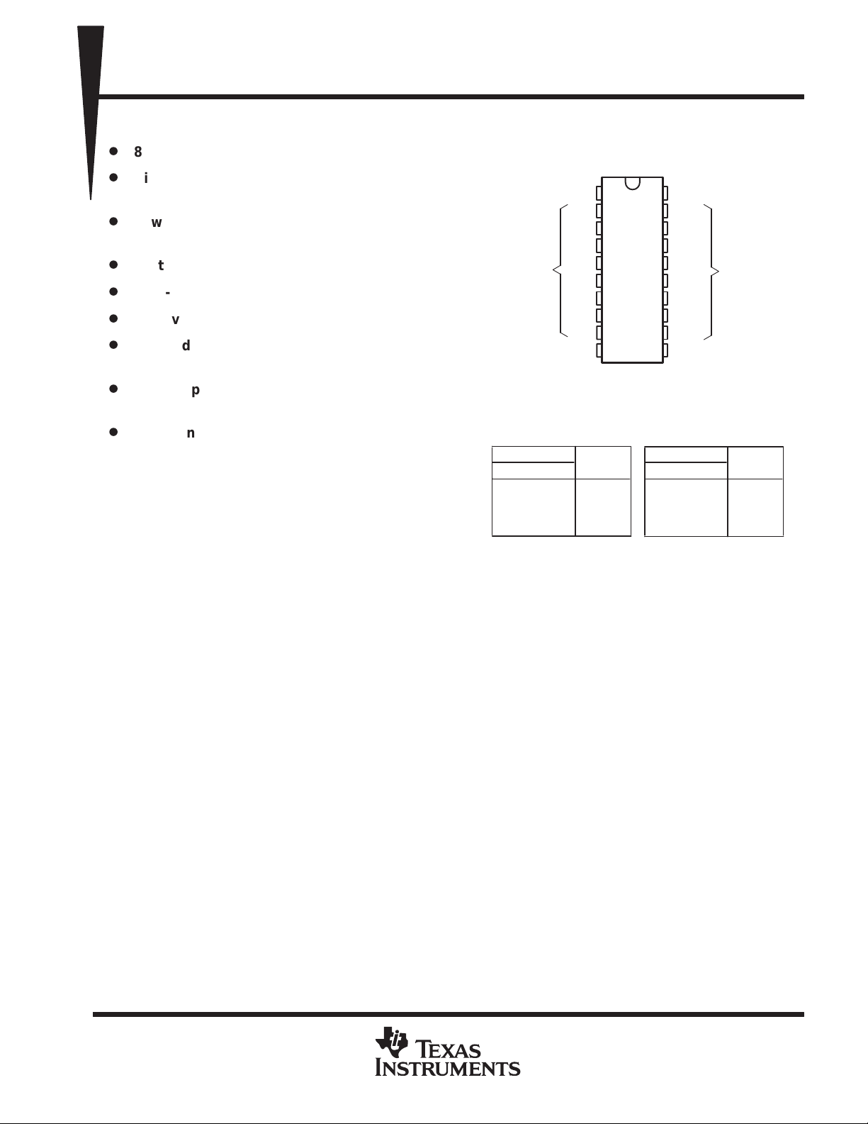
DW OR N PACKAGE
(TOP VIEW)
TE
1
B1
2
B2
3
B3
4
B4
5
B5
6
B6
7
B7
8
9
B8
GND
10
Function Tables
OUTPUT
H
H
L
X
L
X
†
Z
†
Z
20
19
18
17
16
15
14
13
12
11
L
H
X
X
V
CC
D1
D2
D3
D4
D5
D6
D7
D8
PE
INPUTS
L
L
H
X
H
H
X
L
488-1978. The transceiver features driver outputs
that can be operated in either the passive-pullup or 3-state mode. If talk enable (TE) is high, these ports have
the characteristics of passive-pullup outputs when pullup enable (PE) is low and of 3-state outputs when PE
is high. Taking TE low places these ports in the high-impedance state. Taking TE and PE low places both the
drivers and receivers in the high-impedance state. The driver outputs are designed to handle loads up to 48 mA
of sink current.
Terminal
I/O Ports
OUTPUT
L
H
Z
Z
An active turn-off feature is incorporated into the bus-terminating resistors so that the device exhibits a high
impedance to the bus when V
= 0. When combined with the SN75ALS161 or SN75ALS162 management bus
CC
transceiver, the pair provides the complete 16-wire interface for the IEEE 488 bus.
The SN75ALS165 is manufactured in a 20-pin package and is characterized for operation from 0°C to 70°C.
PRODUCTION DATA information is current as of publication date.
Products conform to specifications per the terms of Texas Instruments
standard warranty. Production processing does not necessarily include
testing of all parameters.
POST OFFICE BOX 655303 • DALLAS, TEXAS 75265
Copyright 1989, Texas Instruments Incorporated
1
Page 2
SN75ALS165
OCTAL GENERAL-PURPOSE INTERFACE BUS TRANSCEIVER
SLLS023B – JUNE 1986 – REVISED AUGUST 1989
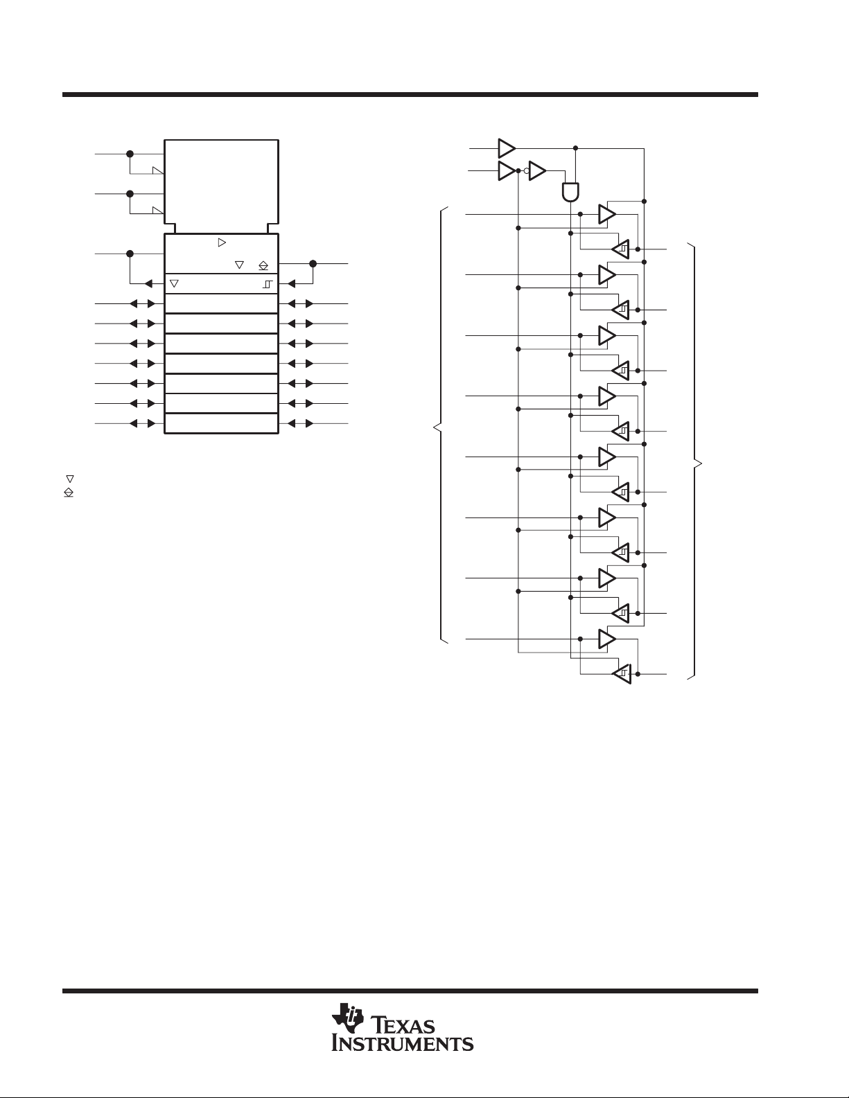
logic symbol
11
PE
1
TE
19
D1
18
D2
17
D3
16
D4
15
D5
14
D6
13
D7
12
D8
†
This symbol is in accordance with ANSI/IEEE Std 91-1984
and IEC Publication 617-12.
Designates 3-state outputs
Designates passive-pullup outputs
†
M1 [3S]/G5
M2 [0C]
EN3 [XMT]
5EN4 [RCV]
4
/23 (1 )
1
logic diagram (positive logic)
11
PE
1
TE
19
D1
2
B1
3
B2
4
B3
5
B4
6
B5
7
B6
8
B7
9
B8
Terminal
I/O Ports
D2
D3
D4
D5
D6
18
17
16
15
14
2
B1
3
B2
4
B3
5
B4
GPIB
6
I/O Ports
B5
D7
D8
13
12
7
B6
8
B7
9
B8
2
POST OFFICE BOX 655303 • DALLAS, TEXAS 75265
Page 3
PACKAGE
A
A
High-level output current, I
Low-level output current, I
mA
OCTAL GENERAL-PURPOSE INTERFACE BUS TRANSCEIVER
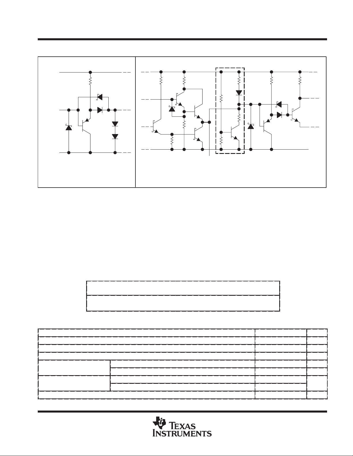
schematics of inputs and outputs
SN75ALS165
SLLS023B – JUNE 1986 – REVISED AUGUST 1989
EQUIVALENT OF ALL CONTROL INPUTS
V
CC
9 kΩ
NOM
Input
GND
Driver output Req = 30 Ω NOM
Receiver output Req = 110 Ω NOM
Circuit inside dashed lines is on the driver outputs only.
EQUIVALENT OF ALL INPUT/OUTPUT PORTS
1.7 kΩ
NOM
4 kΩ
NOM
4 kΩ
NOM
R
eq
Input/Output Port
10 kΩ
NOM
absolute maximum ratings over operating free-air temperature range (unless otherwise noted)
Supply voltage, VCC (see Note 1) 7 V. . . . . . . . . . . . . . . . . . . . . . . . . . . . . . . . . . . . . . . . . . . . . . . . . . . . . . . . . . . . .
Input voltage 5.5 V. . . . . . . . . . . . . . . . . . . . . . . . . . . . . . . . . . . . . . . . . . . . . . . . . . . . . . . . . . . . . . . . . . . . . . . . . . . . .
Low-level driver output current 100 mA. . . . . . . . . . . . . . . . . . . . . . . . . . . . . . . . . . . . . . . . . . . . . . . . . . . . . . . . . . . .
Continuous total power dissipation See Dissipation Rating Table. . . . . . . . . . . . . . . . . . . . . . . . . . . . . . . . . . . . .
Operating free-air temperature range 0°C to 70°C. . . . . . . . . . . . . . . . . . . . . . . . . . . . . . . . . . . . . . . . . . . . . . . . . .
Storage temperature range –65°C to 150°C. . . . . . . . . . . . . . . . . . . . . . . . . . . . . . . . . . . . . . . . . . . . . . . . . . . . . . . .
Lead temperature 1,6 mm (1/16 inch) from the case for 10 seconds 260°C. . . . . . . . . . . . . . . . . . . . . . . . . . . .
NOTE 1: All voltage values are with respect to network ground terminal.
recommended operating conditions
Supply voltage, V
High-level input voltage, V
Low-level input voltage, V
Operating free-air temperature, T
DISSIPATION RATING TABLE
T
≤ 25°C DERATING FACTOR T
POWER RATING ABOVE TA = 25°C
DW 1025 mW 8.2 mW/°C 656 mW
N 1150 mW 9.2 mW/°C 736 mW
CC
IH
IL
p
p
OH
OL
Bus ports with pullups active –5.2 mA
Terminal ports –800 µA
Bus ports 48
Terminal ports 16
A
POST OFFICE BOX 655303 • DALLAS, TEXAS 75265
= 70°C
POWER RATING
MIN NOM MAX UNIT
4.75 5 5.25 V
2 V
0.8 V
0 70 °C
3
Page 4

SN75ALS165
V
‡
High-level output voltage
V
VOLLow-level output voltage
V
V
Voltage at bus port
Driver disabled
V
I/O(bus)
I
mA
ICCSupply current
No load
mA
OCTAL GENERAL-PURPOSE INTERFACE BUS TRANSCEIVER
SLLS023B – JUNE 1986 – REVISED AUGUST 1989
electrical characteristics over recommended ranges of supply voltage and operating free-air
temperature (unless otherwise noted)
PARAMETER TEST CONDITIONS MIN
V
IK
V
hys
OH
I
I
I
IH
I
IL
I/O(bus)
I
OS
C
I/O(bus)
†
All typical values are at VCC = 5 V, TA = 25°C.
‡
VOH applies for 3-state outputs only.
Input clamp voltage II = –18 mA –0.8 1.5 V
Hysteresis (VT+ – VT–) Bus 0.4 0.65 V
p
p
Input current at
maximum input voltage
High-level input current
Low-level input current
p
Current into bus port
Short-circuit output
current
pp
Bus-port capacitance VCC = 5 V to 0, V
Terminal IOH = –800 µA, TE at 0.8 V 2.7 3.5
Bus IOH = –5.2 mA, PE and TE at 2 V 2.5 3.3
Terminal IOL = 16 mA, TE at 0.8 V 0.3 0.5
Bus IOL = 48 mA, TE at 2 V 0.35 0.5
Terminal VI = 5.5 V 0.2 100 µA
Terminal
and
control
inputs
Power on
Power off VCC = 0, V
Terminal –15 –35 –75
Bus
VI = 2.7 V 0.1 20 µA
VI = 0.5 V –10 –100 µA
I
= 0 2.5 3 3.7
I(bus)
I
= –12 mA –1.5
I(bus)
V
= –1.5 V to 0.4 V –1.3
I(bus)
V
= 0.4 V to 2.5 V 0 –3.2
I(bus)
V
Driver disabled
= 2.5 V to 3.7 V
I(bus)
V
= 3.7 V to 5 V 0 2.5
I(bus)
V
= 5 V to 5.5 V 0.7 2.5
I(bus)
= 0 to 2.5 V 40 µA
I(bus)
–25 –50 –125
Terminal outputs low and enabled 42 65
Bus outputs low and enabled 52 80
= 0 to 2 V, f = 1 MHz 30 pF
I/O
TYP
†
MAX UNIT
–3.2
2.5
mA
4
POST OFFICE BOX 655303 • DALLAS, TEXAS 75265
Page 5
Terminal
Bus
L
,
ns
Bus
Terminal
L
,
ns
TE
Bus
L
,
ns
TE
Terminal
L
,
ns
PE
Terminal
L
ns
SN75ALS165
OCTAL GENERAL-PURPOSE INTERFACE BUS TRANSCEIVER
SLLS023B – JUNE 1986 – REVISED AUGUST 1989
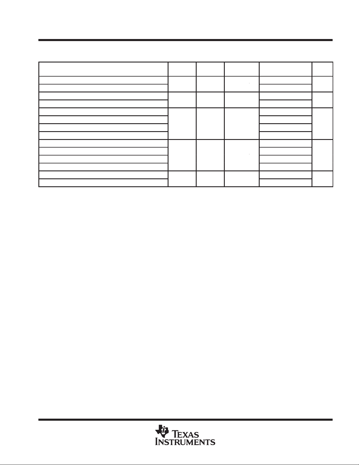
switching characteristics over recommended range of operating free-air temperature (unless
otherwise noted), V
PARAMETER
t
Propagation delay time, low-to-high-level output
PLH
t
Propagation delay time, high-to-low-level output
PHL
t
Propagation delay time, low-to-high-level output
PLH
t
Propagation delay time, high-to-low-level output
PHL
t
Output enable time to high level 19 30
PZH
t
Output disable time from high level
PHZ
t
Output enable time to low level
PZL
t
Output disable time from low level 9 20
PLZ
t
Output enable time to high level 13 30
PZH
t
Output disable time from high level
PHZ
t
Output enable time to low level
PZL
t
Output disable time from low level 11 20
PLZ
t
Output pullup enable time
en
t
Output pullup disable time
dis
†
All typical values are at TA = 25°C.
CC
= 5 V
FROM
(INPUT)TO(OUTPUT)
TEST
CONDITIONS
C
= 30 pF,
See Figure 1
C
= 30 pF,
See Figure 2
C
= 15 pF,
See Figure 3
C
= 15 pF,
See Figure 4
CL = 15 pF,
See Figure 5
MIN
†
TYP
7 20
8 20
7 14
9 14
5 12
16 35
12 20
12 20
11 22
6 12
MAX UNIT
POST OFFICE BOX 655303 • DALLAS, TEXAS 75265
5
Page 6
SN75ALS165
OCTAL GENERAL-PURPOSE INTERFACE BUS TRANSCEIVER
SLLS023B – JUNE 1986 – REVISED AUGUST 1989
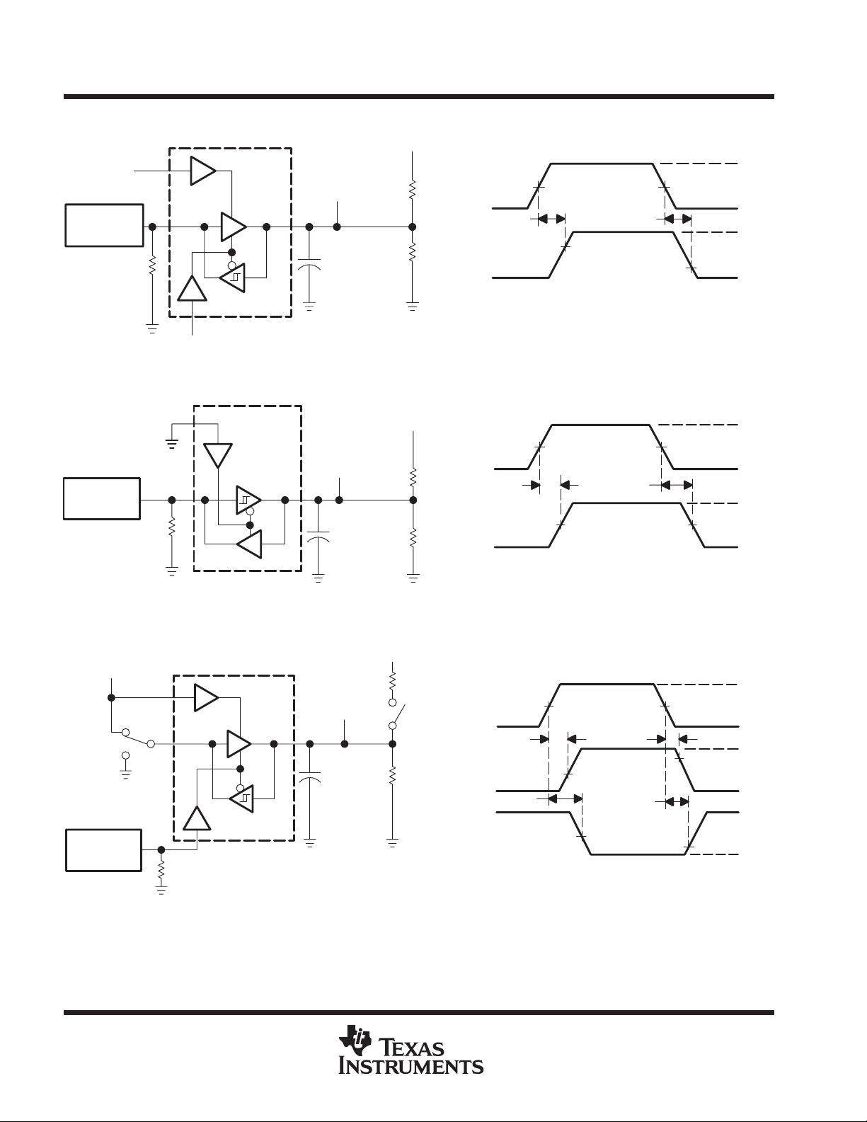
PARAMETER MEASUREMENT INFORMATION
5 V
PE
3 V
Generator
(see Note A)
50 Ω
Output
D
TE
3 V
TEST CIRCUIT VOLTAGE WAVEFORMS
B
CL = 30 pF
(see Note B)
200 Ω
480 Ω
Figure 1. Terminal-to-Bus Test Circuit and Voltage Waveforms
D Input
t
PLH
B Output
1.5 V
2.2 V
t
PHL
1.5 V
1.0 V
3 V
0 V
V
V
OH
OH
Generator
(see Note A)
3 V
Generator
(see Note A)
50 Ω
S1
PE
D
TE
Output
B
TEST CIRCUIT VOLTAGE WAVEFORMS
D
CL = 30 pF
(see Note B)
4.3 V
240 Ω
3 kΩ
B Input
t
PLH
D Output
1.5 V
1.5 V
Figure 2. Bus-to-Terminal Test Circuit and Voltage Waveforms
5 V
200 Ω
TE Input
t
PZH
B Output
S1 to 3 V
S2 Open
t
PZL
B Output
S1 to GND
S2 Closed
2 V
1 V
50 Ω
TE
Output
B
CL = 15 pF
(see Note B)
S2
480 Ω
t
PLH
t
PHZ
t
PLZ
1.5 V
1.5 V1.5 V
90%
0.5 V
1.5 V
3 V
0 V
V
OH
V
OL
3 V
0 V
V
OH
0.8 V
3.5 V
V
OL
TEST CIRCUIT VOLTAGE WAVEFORMS
Figure 3. TE-to-Bus Test Circuit and Voltage Waveforms
NOTES: A. The input pulse is supplied by a generator having the following characteristics: PRR ≤ 1 MHz, 50% duty cycle, tr ≤ 6 ns, tf ≤ 6 ns,
6
ZO=50Ω.
B. CL includes probe and jig capacitance.
POST OFFICE BOX 655303 • DALLAS, TEXAS 75265
Page 7
SN75ALS165
OCTAL GENERAL-PURPOSE INTERFACE BUS TRANSCEIVER
SLLS023B – JUNE 1986 – REVISED AUGUST 1989
PARAMETER MEASUREMENT INFORMATION
Generator
(See Note A)
3 V
Generator
(see Note A)
50 Ω
3 V
S1
50 Ω
PE
TE
4.3 V
TE
Output
240 Ω
D
CL = 15 pF
B
TEST CIRCUIT VOLTAGE WAVEFORMS
(see Note B)
3 kΩ
S2
TE Input
t
PZH
D Output
S1 to 3 V
S2 Open
t
PZL
D Output
S1 to GND
S2 Closed
1.5 V
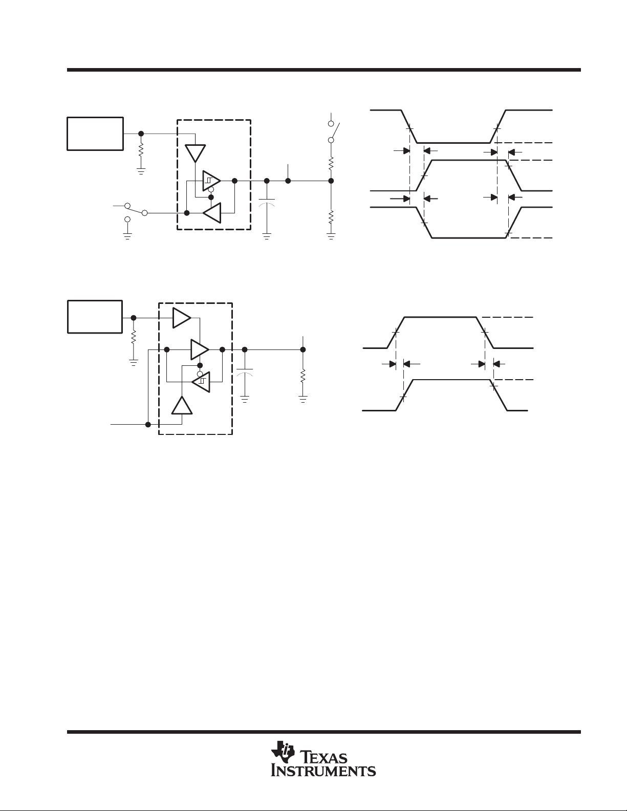
Figure 4. TE-to-T erminal Test Circuit and Voltage Waveforms
PE Input
t
en
B Output
2 V
BD
CL = 15 pF
(see Note B)
Output
RL = 480 Ω
1 V
t
dis
t
PHZ
t
PLZ
1.5 V1.5 V
1.5 V1.5 V
90%
90%
0.7 V
VOL ≈ 0.8 V
3 V
0 V
V
OH
3 V
0 V
V
0 V
4 V
V
OH
OL
TEST CIRCUIT VOLTAGE WAVEFORMS
Figure 5. PE-to-Bus Test Circuit and Voltage Waveforms
NOTES: A. The input pulse is supplied by a generator having the following characteristics: PRR ≤ 1 MHz, 50% duty cycle, tr ≤ 6 ns, tf ≤ 6 ns,
ZO=50Ω.
B. CL includes probe and jig capacitance.
POST OFFICE BOX 655303 • DALLAS, TEXAS 75265
7
Page 8
SN75ALS165
OCTAL GENERAL-PURPOSE INTERFACE BUS TRANSCEIVER
SLLS023B – JUNE 1986 – REVISED AUGUST 1989
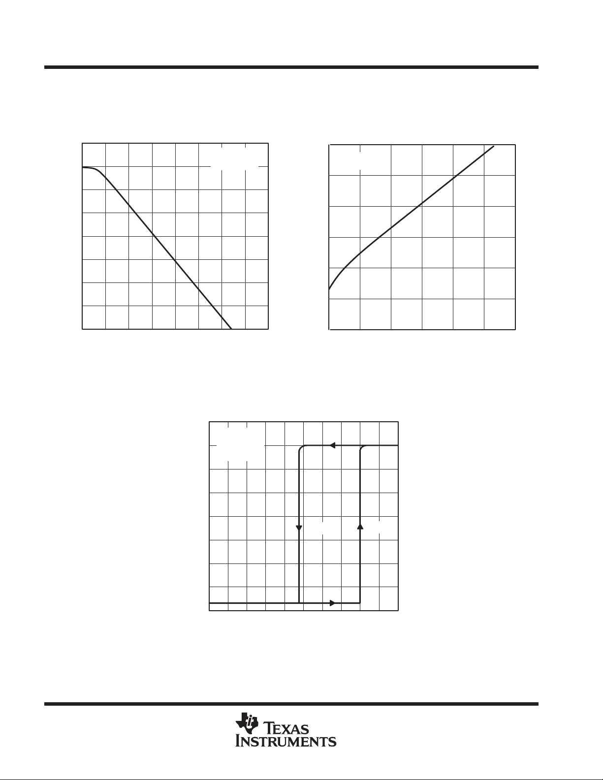
TYPICAL CHARACTERISTICS
TERMINAL HIGH-LEVEL OUTPUT VOLTAGE
HIGH-LEVEL OUTPUT CURRENT
4
3.5
3
2.5
2
1.5
– High-Level Output Voltage – V
1
OH
V
0.5
0
0 – 5 – 10 – 15 – 20 – 25
IOH – High-Level Output Current – mA
vs
Figure 6
VCC = 5 V
TA = 25°C
– 30 – 35 – 40
4
VCC = 5 V
No Load
3.5
TA = 25°C
3
TERMINAL LOW-LEVEL OUTPUT VOLTAGE
LOW-LEVEL OUTPUT CURRENT
0.6
VCC = 5 V
TA = 25°C
0.5
0.4
0.3
0.2
– Low-Level Output Voltage – V
OL
0.1
V
0
01020
IOL – Low-Level Output Current – mA
TERMINAL OUTPUT VOLTAGE
vs
BUS INPUT VOLTAGE
vs
30 40 50
Figure 7
60
2.5
2
V
T+
1.5
– Output Voltage – V
O
V
1
0.5
0
0 0.2 0.4 0.6 0.8 1 1.2
VI – Input Voltage – V
V
T–
1.4 1.6 1.8 2
Figure 8
8
POST OFFICE BOX 655303 • DALLAS, TEXAS 75265
Page 9
SN75ALS165
OCTAL GENERAL-PURPOSE INTERFACE BUS TRANSCEIVER
SLLS023B – JUNE 1986 – REVISED AUGUST 1989
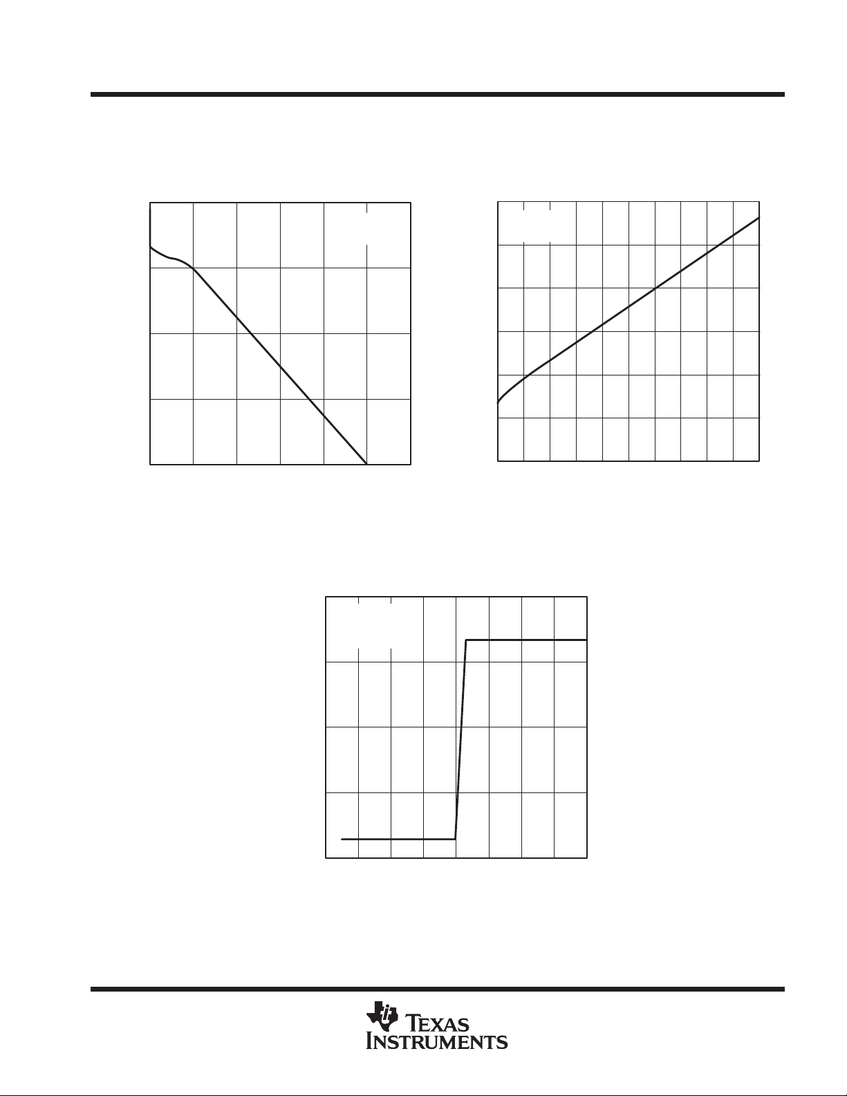
TYPICAL CHARACTERISTICS
BUS HIGH-LEVEL OUTPUT VOLTAGE
BUS HIGH-LEVEL OUTPUT CURRENT
4
3
2
1
– High-Level Output Voltage – V
OH
V
0
0 – 10 – 20 – 30 – 40
IOH – High-Level Output Current – mA
Figure 9
vs
4
3
VCC = 5 V
TA = 25°C
V
– 50 – 60
BUS OUTPUT VOLTAGE
vs
TERMINAL INPUT VOLTAGE
VCC = 5 V
No Load
TA = 25°C
BUS LOW-LEVEL OUTPUT VOLTAGE
BUS LOW-LEVEL OUTPUT CURRENT
0.6
VCC = 5 V
TA = 25°C
0.5
0.4
0.3
0.2
– Low-Level Output Voltage – V
OL
0.1
0
0 102030405060
IOL – Low-Level Output Current – mA
Figure 10
vs
70 80 90 100
2
– Output Voltage – V
O
V
1
0
0.9 1 1.1 1.2 1.3 1.4
VI – Input Voltage – V
Figure 11
POST OFFICE BOX 655303 • DALLAS, TEXAS 75265
1.5 1.6 1.7
9
Page 10

IMPORTANT NOTICE
T exas Instruments (TI) reserves the right to make changes to its products or to discontinue any semiconductor
product or service without notice, and advises its customers to obtain the latest version of relevant information
to verify, before placing orders, that the information being relied on is current and complete.
TI warrants performance of its semiconductor products and related software to the specifications applicable at
the time of sale in accordance with TI’s standard warranty. Testing and other quality control techniques are
utilized to the extent TI deems necessary to support this warranty. Specific testing of all parameters of each
device is not necessarily performed, except those mandated by government requirements.
Certain applications using semiconductor products may involve potential risks of death, personal injury, or
severe property or environmental damage (“Critical Applications”).
TI SEMICONDUCTOR PRODUCTS ARE NOT DESIGNED, INTENDED, AUTHORIZED, OR WARRANTED
TO BE SUITABLE FOR USE IN LIFE-SUPPORT APPLICATIONS, DEVICES OR SYSTEMS OR OTHER
CRITICAL APPLICATIONS.
Inclusion of TI products in such applications is understood to be fully at the risk of the customer. Use of TI
products in such applications requires the written approval of an appropriate TI officer . Questions concerning
potential risk applications should be directed to TI through a local SC sales office.
In order to minimize risks associated with the customer’s applications, adequate design and operating
safeguards should be provided by the customer to minimize inherent or procedural hazards.
TI assumes no liability for applications assistance, customer product design, software performance, or
infringement of patents or services described herein. Nor does TI warrant or represent that any license, either
express or implied, is granted under any patent right, copyright, mask work right, or other intellectual property
right of TI covering or relating to any combination, machine, or process in which such semiconductor products
or services might be or are used.
Copyright 1998, Texas Instruments Incorporated
 Loading...