

Page 1
DUAL 1-OF-4 DECODER/
DEMULTIPLEXER
The SN54/74LS155 and SN54/74LS156 are high speed Dual 1-of-4
Decoder/Demultiplexers. These devices have two decoders with common
2-bit Address inputs and separate gated Enable inputs. Decoder “a” has an
Enable gate with one active HIGH and one active LOW input. Decoder “b” has
two active LOW Enable inputs. If the Enable functions are satisfied, one
output of each decoder will be LOW as selected by the address inputs. The
LS156 has open collector outputs for wired-OR (DOT-AND) decoding and
function generator applications.
The LS155 and LS156 are fabricated with the Schottky barrier diode
process for high speed and are completely compatible with all Motorola TTL
families.
• Schottky Process for High Speed
• Multifunction Capability
• Common Address Inputs
• True or Complement Data Demultiplexing
• Input Clamp Diodes Limit High Speed Termination Effects
• ESD > 3500 Volts
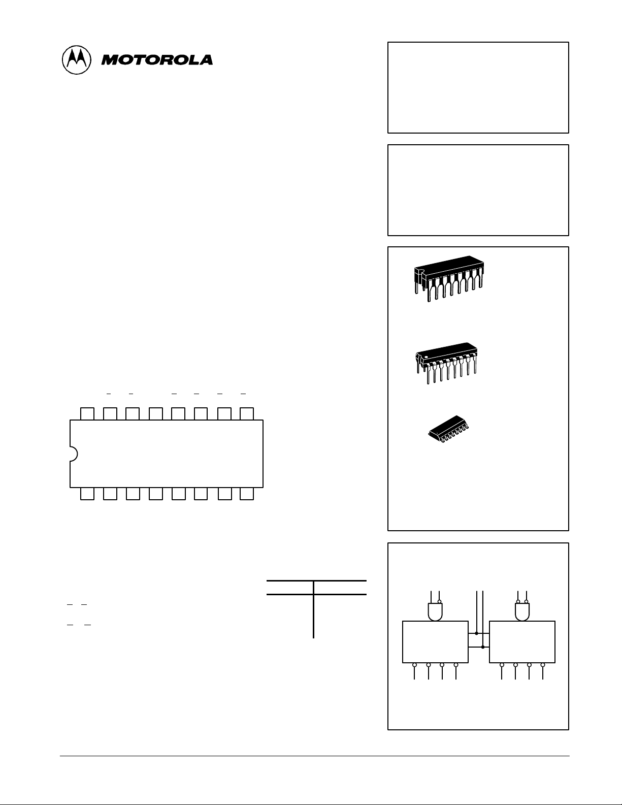
CONNECTION DIAGRAM DIP (TOP VIEW)
V
EbEbA0O
CC
16 15
123456
E
a
14 13 12 11 10 9
EaA1O3aO2aO1aO0aGND
3b
O
O
2b
O
1b
7
0b
NOTE:
The Flatpak version
has the same pinouts
(Connection Diagram) as
the Dual In-Line Package.
8
SN54 /74LS155
SN54 /74LS156
DUAL 1-OF-4 DECODER/
DEMULTIPLEXER
LS156-OPEN-COLLECTOR
LOW POWER SCHOTTKY
J SUFFIX
CERAMIC
16
1
16
1
16
1
ORDERING INFORMATION
SN54LSXXXJ Ceramic
SN74LSXXXN Plastic
SN74LSXXXD SOIC
CASE 620-09
N SUFFIX
PLASTIC
CASE 648-08
D SUFFIX
SOIC
CASE 751B-03
PIN NAMES LOADING (Note a)
HIGH
A0, A
E
, E
a
E
a
O
0–O3
NOTES:
a) 1 TTL Unit Load (U.L.) = 40 µA HIGH/1.6 mA LOW.
b) The Output LOW drive factor is 2.5 U.L. for Military (54) and 5 U.L. for Commercial (74)
Temperature Ranges. The HIGH level drive for the LS156 must be established by an external
resistor.
Address Inputs
1
Enable (Active LOW) Inputs
b
Enable (Active HIGH) Input
Active LOW Outputs (Note b)
0.5 U.L.
0.5 U.L.
0.5 U.L.
10 U.L.
LOW
0.25 U.L.
0.25 U.L.
0.25 U.L.
5 (2.5) U.L.
FAST AND LS TTL DAT A
5-1
LOGIC SYMBOL
1 2 13 3 1415
EE
A
DECODER a DECODER b
0123 0123
7 6 5 4 9 10 11 12
0
A
1
VCC = PIN 16
GND = PIN 8
A
0
A
1
Page 2
SN54/74LS155 • SN54/74LS156
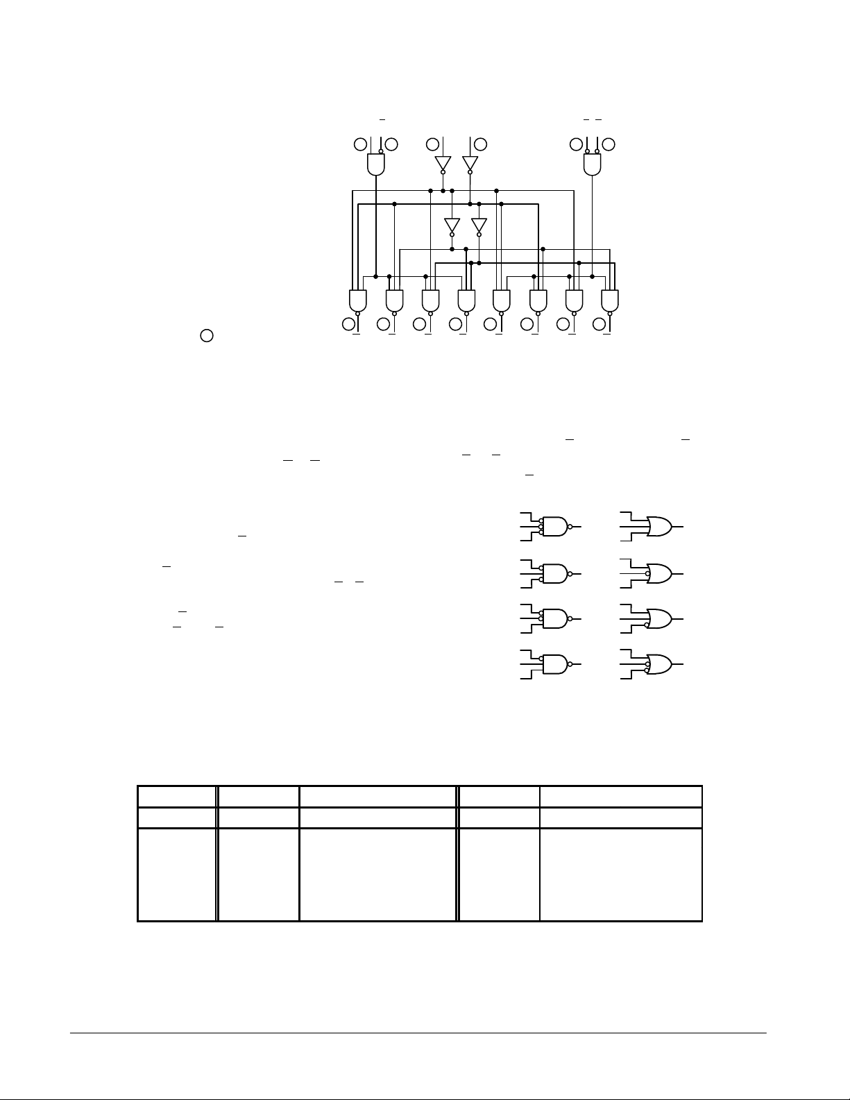
LOGIC DIAGRAM
VCC = PIN 16
GND = PIN 8
= PIN NUMBERS
EaE
a
67
O0aO1aO2aO3aO0bO
FUNCTIONAL DESCRIPTION
The LS155 and LS156 are Dual 1-of-4 Decoder/Demultiplexers with common Address inputs and separate gated
Enable inputs. When enabled, each decoder section accepts
the binary weighted Address inputs (A0, A1) and provides four
mutually exclusive active LOW outputs (O
0–O3
). If the Enable
requirements of each decoder are not met, all outputs of that
decoder are HIGH.
Each decoder section has a 2-input enable gate. The
enable gate for Decoder “a” requires one active HIGH input
and one active LOW input (Ea•E
). In demultiplexing applica-
a
tions, Decoder “a” can accept either true or complemented
data by using the E
for Decoder “b” requires two active LOW inputs (E
or Ea inputs respectively. The enable gate
a
b•Eb
). The
LS155 or LS156 can be used as a 1-of-8 Decoder/Demultiplexer by tying Ea to E
as (A2). The other E
and relabeling the common connection
b
and Ea are connected together to form
b
the common enable.
The LS155 and LS156 can be used to generate all four
minterms of two variables. These four minterms are useful in
some applications replacing multiple gate functions as shown
in Fig. a. The LS156 has the further advantage of being able to
A0A
1
13 15
3
45 9 11 1210
1bO2bO3b
EbE
b
1412
AND the minterm functions by tying outputs together. Any
number of terms can be wired-AND as shown below.
f = (E + A0 + A1) ⋅ (E + A
(E + A
where E = Ea + E
+ A1)
0
a
E
A
0
A
1
E
A
0
A
1
E
A
0
A
1
E
A
0
A
1
+ A1) ⋅ (E + A0 + A1) ⋅
0
; E = Eb + E
b
E
A
0
O
0
A
1
E
A
O
0
1
A
1
E
A
O
0
2
A
1
E
A
O
0
3
A
1
O
0
O
1
O
2
O
3
Figure a
TRUTH TABLE
ADDRESS ENABLE “a” OUTPUT “a” ENABLE “b” OUTPUT “b”
A
A
0
X X L X H H H H H X H H H H
X XXHHHHHXHHHHH
LLHLLHHHL LLHHH
HLHLHLHHLLHLHH
LHHLHHLHLLHHLH
HHHLHHHLLLHHHL
H = HIGH Voltage Level
L = LOW Voltage Level
X = Don’t Care
E
1
E
O
O
O
O
E
E
O
O
O
a
a
0
1
2
3
b
b
0
1
O
2
FAST AND LS TTL DATA
5-2
3
Page 3
SN54/74LS155
VILI
LOW Volt
V
pg
VOHOutput HIGH Volt
CC
,
OH
,
IN IH
VOLOutput LOW Volt
V
V
V
IIHI
HIGH C
t
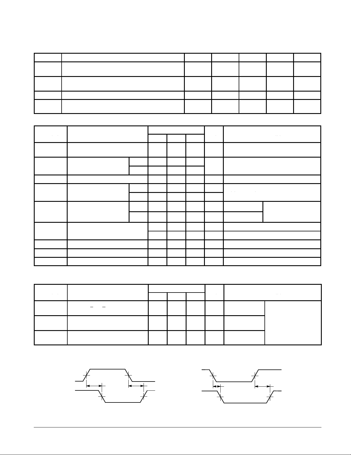
GUARANTEED OPERATING RANGES
Symbol Parameter Min Typ Max Unit
V
CC
T
A
I
OH
I
OL
DC CHARACTERISTICS OVER OPERATING TEMPERATURE RANGE (unless otherwise specified)
Symbol Parameter
V
IH
V
IK
I
IL
I
OS
I
CC
Note 1: Not more than one output should be shorted at a time, nor for more than 1 second.
Supply Voltage 54
Operating Ambient Temperature Range 54
Output Current — High 54, 74 –0.4 mA
Output Current — Low 54
Limits
Min Typ Max
Input HIGH Voltage 2.0 V
nput
Input Clamp Diode Voltage –0.65 –1.5 V VCC = MIN, IIN = –18 mA
nput
Input LOW Current –0.4 mA VCC = MAX, VIN = 0.4 V
Short Circuit Current (Note 1) –20 –100 mA VCC = MAX
Power Supply Current 10 mA VCC = MAX
age
age
age
urren
54 0.7
74 0.8
54 2.5 3.5 V
74 2.7 3.5 V
54, 74 0.25 0.4 V IOL = 4.0 mA
74 0.35 0.5 V IOL = 8.0 mA
74
74
74
20 µA VCC = MAX, VIN = 2.7 V
0.1 mA VCC = MAX, VIN = 7.0 V
4.5
4.75
–55
0
Unit Test Conditions
Guaranteed Input HIGH Voltage for
All Inputs
Guaranteed Input LOW Voltage for
All Inputs
VCC = MIN, IOH = MAX, VIN = V
or VIL per Truth Table
5.0
5.0
25
25
5.5
5.25
125
70
4.0
8.0
VCC = VCC MIN,
=
IN
IL
per Truth Table
or
IH
IH
V
°C
mA
AC CHARACTERISTICS (T
= 25°C)
A
Symbol Parameter
t
PLH
t
PHL
t
PLH
t
PHL
t
PLH
t
PHL
Propagation Delay
Address, E
Propagation Delay
Address to Output
Propagation Delay
Ea to Output
1.3 V
V
V
IN
OUT
or Eb to Output
a
Figure 1 Figure 2
t
PHL
1.3 V
Limits
Min Typ Max
10
19
17
19
18
18
AC WAVEFORMS
1.3 V
t
PLH
1.3 V
FAST AND LS TTL DATA
5-3
15
30
26
30
27
27
V
Unit Test Conditions
ns Figure 1
ns Figure 2
ns Figure 1
V
IN
OUT
1.3 V
t
PHL
1.3 V
1.3 V
VCC = 5.0 V
CL = 15 pF
t
PLH
1.3 V
Page 4
SN54/74LS156
VILI
LOW Volt
V
pg
VOLOutput LOW Volt
V
V
V
IIHI
HIGH C
t
R
L
kΩ
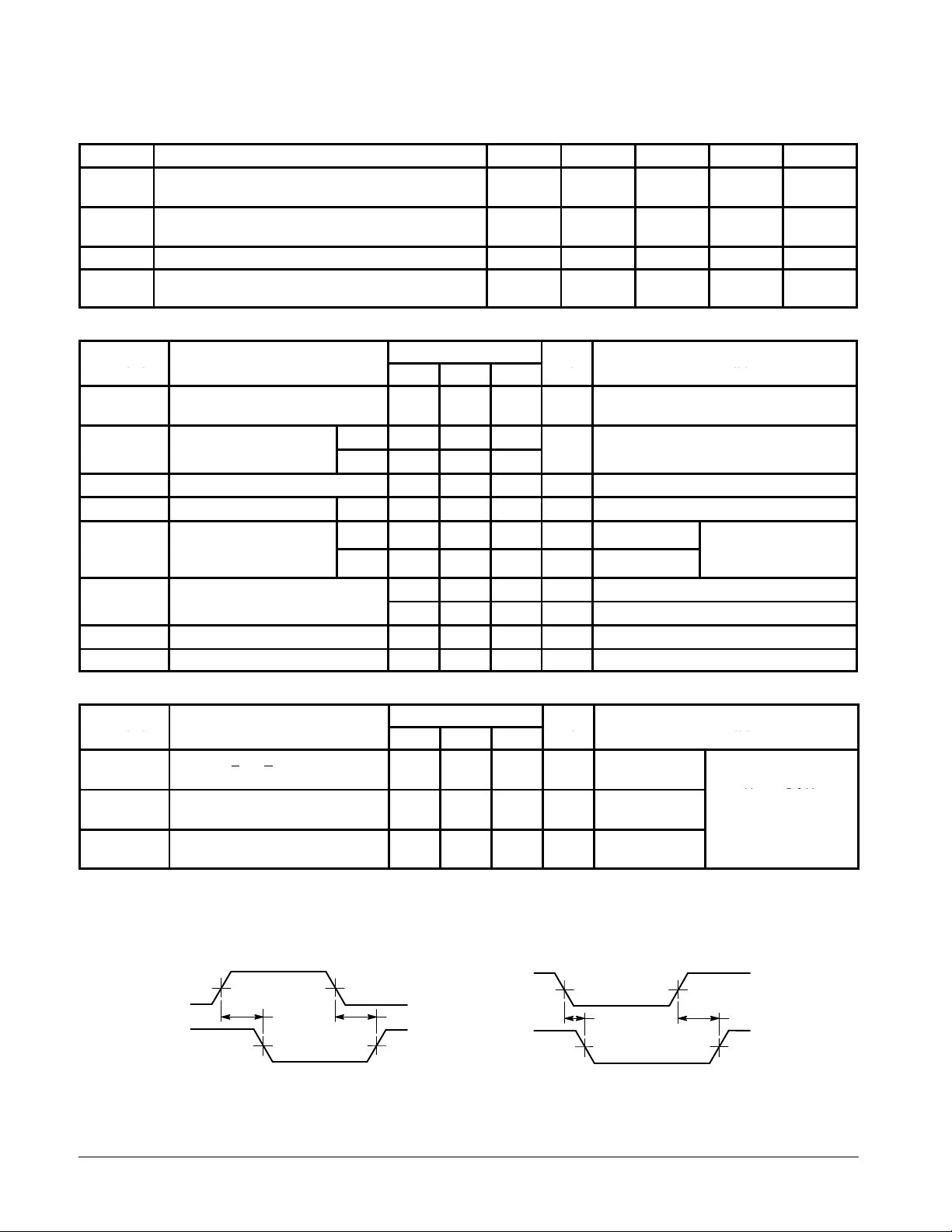
GUARANTEED OPERATING RANGES
Symbol Parameter Min Typ Max Unit
V
CC
T
A
V
OH
I
OL
DC CHARACTERISTICS OVER OPERATING TEMPERATURE RANGE (unless otherwise specified)
Symbol Parameter
V
IH
V
IK
I
OH
I
IL
I
CC
Supply Voltage 54
Operating Ambient Temperature Range 54
Output Voltage — High 54, 74 5.5 V
Output Current — Low 54
Limits
Min Typ Max
Input HIGH Voltage 2.0 V
nput
Input Clamp Diode Voltage –0.65 –1.5 V VCC = MIN, IIN = –18 mA
Output HIGH Current 54, 74 100 µA VCC = MIN, VOH = MAX
nput
Input LOW Current –0.4 mA VCC = MAX, VIN = 0.4 V
Power Supply Current 10 mA VCC = MAX
age
age
urren
54 0.7
74 0.8
54, 74 0.25 0.4 V IOL = 4.0 mA
74 0.35 0.5 V IOL = 8.0 mA
74
74
74
20 µA VCC = MAX, VIN = 2.7 V
0.1 mA VCC = MAX, VIN = 7.0 V
4.5
4.75
–55
0
Unit Test Conditions
Guaranteed Input HIGH Voltage for
All Inputs
Guaranteed Input LOW Voltage for
All Inputs
5.0
5.0
25
25
5.5
5.25
125
70
4.0
8.0
VCC = VCC MIN,
=
IN
IL
per Truth Table
or
IH
V
°C
mA
AC CHARACTERISTICS (T
Symbol Parameter
t
PLH
t
PHL
t
PLH
t
PHL
t
PLH
t
PHL
Propagation Delay
Address, E
Propagation Delay
Address to Output
Propagation Delay
Ea to Output
1.3 V
V
OUT
V
IN
or Eb to Output
a
= 25°C)
A
Limits
Min Typ Max
25
34
31
34
32
32
Unit Test Conditions
40
51
46
51
48
48
ns Figure 1
ns Figure 2
ns Figure 1
AC WAVEFORMS
t
PHL
1.3 V
1.3 V
t
PLH
1.3 V
V
V
IN
OUT
1.3 V
t
PHL
1.3 V
Figure 1 Figure 2
1.3 V
VCC = 5.0 V
CL = 15 pF
= 2.0
R
= 2.0 kΩ
t
PLH
1.3 V
FAST AND LS TTL DATA
5-4
 Loading...