

Page 1
RETRIGGERABLE MONOSTABLE
MULTIVIBRATORS
SN54/74LS122
SN54/74LS123
These dc triggered multivibrators feature pulse width control by three methods. The basic pulse width is programmed by selection of external resistance
and capacitance values. The LS122 has an internal timing resistor that allows
the circuits to be used with only an external capacitor. Once triggered, the basic pulse width may be extended by retriggering the gated low-level-active (A)
or high-level-active (B) inputs, or be reduced by use of the overriding clear.
• Overriding Clear Terminates Output Pulse
• Compensated for V
and Temperature Variations
CC
• DC Triggered from Active-High or Active-Low Gated Logic Inputs
• Retriggerable for Very Long Output Pulses, up to 100% Duty Cycle
• Internal Timing Resistors on LS122
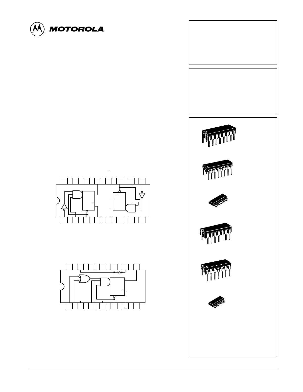
SN54/74LS123 (TOP VIEW)
(SEE NOTES 1 THRU 4)
1R
ext/
1
C
V
CC
16 15
123456
1A
C
ext
1B 1
1Q 2Q
ext
14 13 12 11 10 9
Q
Q
CLR
1Q
CLR
SN54/74LS122 (TOP VIEW)
(SEE NOTES 1 THRU 4)
R
ext/
C
V
CC
14 13 12 11 10 9
ext
NC C
ext
CLR
CLR
Q
Q
2Q 2
C
NC R
R
2
ext
int
Q
R
int
2B
7
2
ext/
C
ext
Q
8
2A
8
GND
RETRIGGERABLE MONOSTABLE
MULTIVIBRATORS
LOW POWER SCHOTTKY
J SUFFIX
CERAMIC
16
1
16
1
16
1
14
1
14
1
CASE 620-09
N SUFFIX
PLASTIC
CASE 648-08
D SUFFIX
SOIC
CASE 751B-03
J SUFFIX
CERAMIC
CASE 632-08
N SUFFIX
PLASTIC
CASE 646-06
Q
CLR
123456
A1 A2 B1 B2 CLR Q
NC — NO INTERNAL CONNECTION.
NOTES:
1. An external timing capacitor may be connected between C
2. To use the internal timing resistor of the LS122, connect R
3. For improved pulse width accuracy connect an external resistor between R
VCC with R
4. T o obtain variable pulse widths, connect an external variable resistance between R
and VCC.
open-circuited.
int
and R
ext
to VCC.
int
7
GND
ext/Cext
(positive).
ext/Cext
FAST AND LS TTL DAT A
5-1
and
int/Cext
D SUFFIX
14
1
SOIC
CASE 751A-02
ORDERING INFORMATION
SN54LSXXXJ Ceramic
SN74LSXXXN Plastic
SN74LSXXXD SOIC
Page 2
SN54/74LS122 • SN54/74LS123
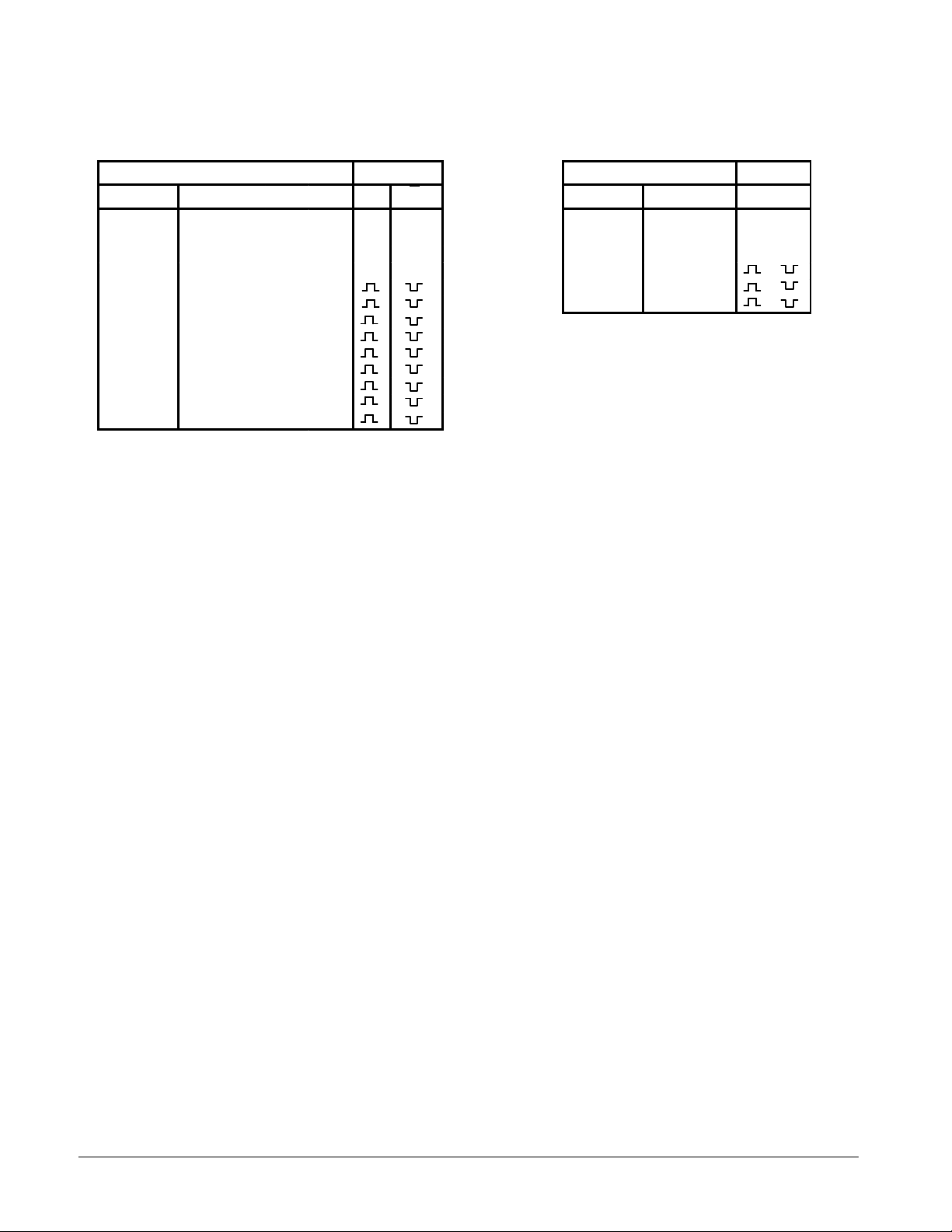
LS122
FUNCTIONAL TABLE
INPUTS OUTPUTS
CLEAR A1 A2 B1 B2 Q Q
L X X X X L H
X H HXXLH
X XXLXLH
X XXXLLH
H LX↑H
H LXH↑
H XL↑H
H XLH↑
H H↓HH
H ↓ ↓HH
H ↓HHH
↑ LXHH
↑ XLHH
TYPICAL APPLICATION DATA
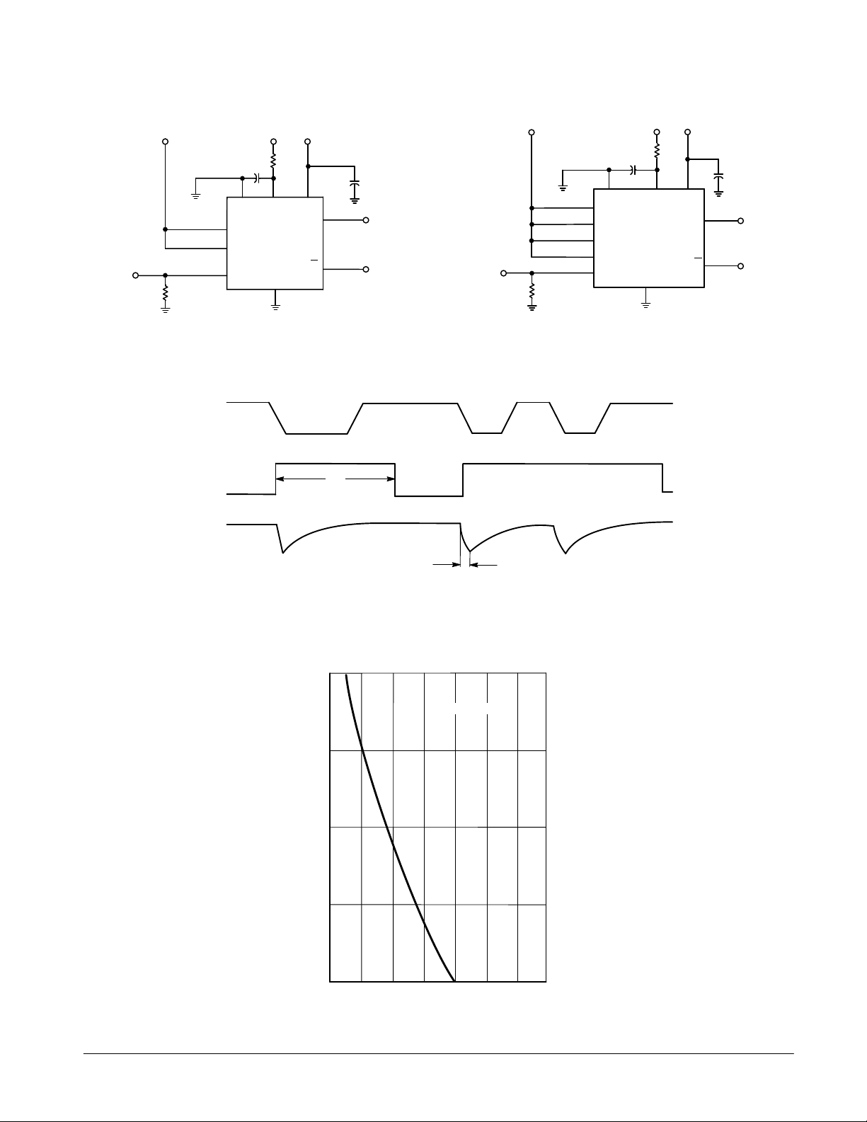
The output pulse tW is a function of the external components, C
of C
and R
ext
≥1000 pF, the output pulse at VCC = 5.0 V and VRC =
ext
ext
or C
ext
and R
on the LS122. For values
int
5.0 V (see Figures 1, 2, and 3) is given by
If C
ext
The C
tW = K R
ext Cext
is on pF and R
terminal of the LS122 and LS123 is an internal
ext
where K is nominally 0.45
is in kΩ then tW is in nanoseconds.
ext
connection to ground, however for the best system performance C
Care should be taken to keep R
should be hard-wired to ground.
ext
ext
and C
as close to the
ext
monostable as possible with a minimum amount of inductance
between the R
ext/Cext
junction and the R
ext/Cext
pin. Good
groundplane and adequate bypassing should be designed
into the system for optimum performance to insure that no
false triggering occurs.
It should be noted that the C
pin is internally connected
ext
to ground on the LS122 and LS123, but not on the LS221.
Therefore, if C
is hard-wired externally to ground, substitu-
ext
tion of a LS221 onto a LS123 socket will cause the LS221 to
become non-functional.
The switching diode is not needed for electrolytic capacitance application and should not be used on the LS122 and
LS123.
To find the value of K for C
≥ 1000 pF, refer to Figure 4.
ext
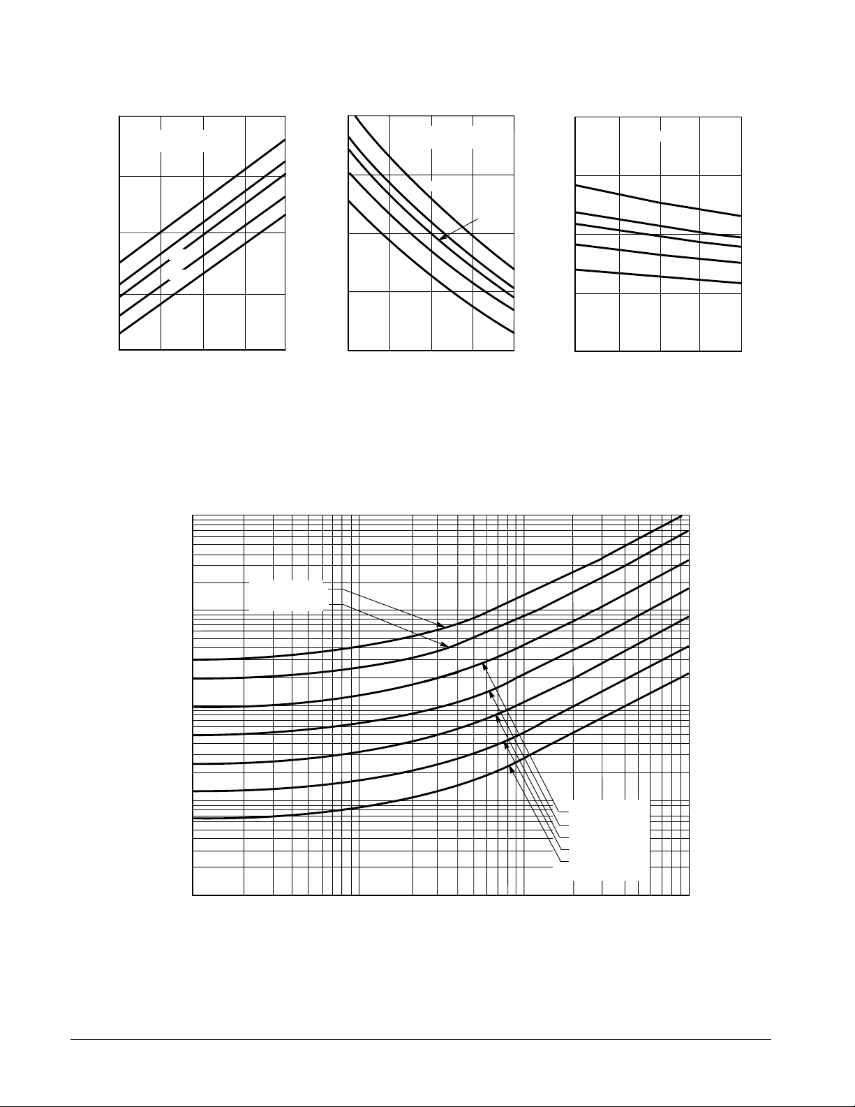
V ariations on VCC or VRC can cause the value of K to change,
as can the temperature of the LS123, LS122. Figures 5 and
6 show the behavior of the circuit shown in Figures 1 and 2 if
LS123
FUNCTIONAL TABLE
INPUTS OUTPUTS
CLEAR A B Q Q
L X X L H
X H XLH
X X LLH
H L ↑
H ↓ H
↑ L H
separate power supplies are used for VCC and VRC. If VCC is
tied to VRC, Figure 7 shows how K will vary with VCC and
temperature. Remember, the changes in R
ext
and C
ext
with
temperature are not calculated and included in the graph.
As long as C
(SN74LS122/123) or 5K ≤ R
the change in K with respect to R
If C
≤ 1000 pF the graph shown on Figure 8 can be used
ext
≥ 1000 pF and 5K ≤ R
ext
≤ 160 K (SN54LS122/123),
ext
is negligible.
ext
≤ 260K
ext
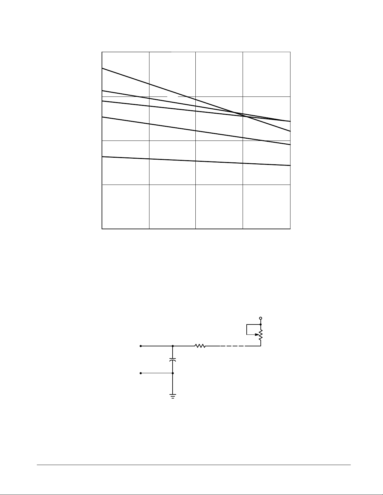
to determine the output pulse width. Figure 9 shows how K will
change for C
≤ 1000 pF if VCC and VRC are connected to the
ext
same power supply. The pulse width tW in nanoseconds is
approximated by
tW = 6 + 0.05 C
(pF) + 0.45 R
ext
ext
(kΩ) C
+ 1 1.6 R
ext
ext
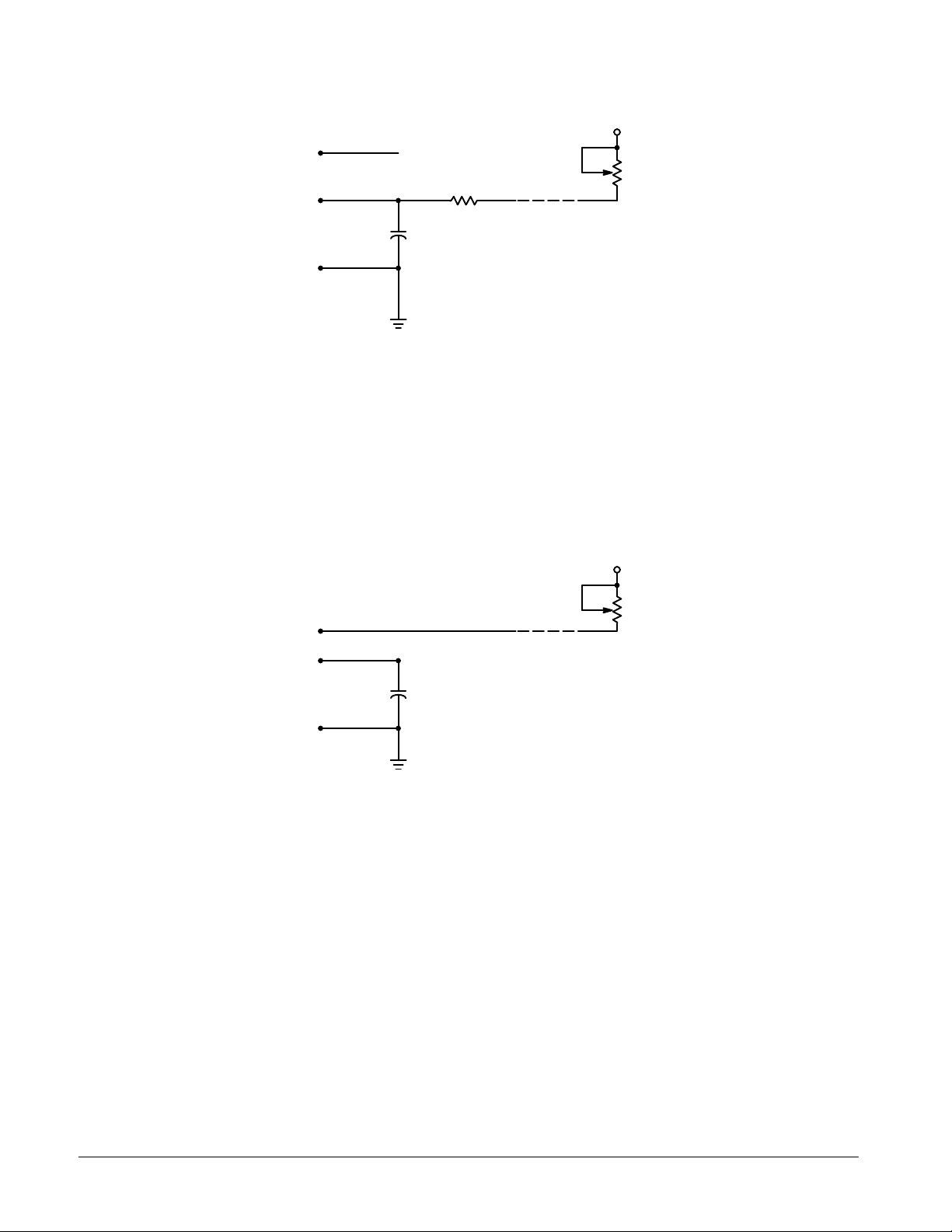
In order to trim the output pulse width, it is necessary to
include a variable resistor between VCC and the R
or between VCC and the R
and 12 show how this can be done. R
pin of the LS122. Figure 10, 1 1,
ext
remote should be kept
ext
ext/Cext
pin
as close to the monostable as possible.
Retriggering of the part, as shown in Figure 3, must not
occur before C
have any effect. The discharge time of C
guaranteed to be less than 0.22 C
C
(pF).
ext
is discharged or the retrigger pulse will not
ext
ext
in nanoseconds is
ext
(pF) and is typically 0.05
For the smallest possible deviation in output pulse widths
from various devices, it is suggested that C
be kept
ext
≥ 1000 pF.
FAST AND LS TTL DATA
5-2
Page 3
SN54/74LS122 • SN54/74LS123
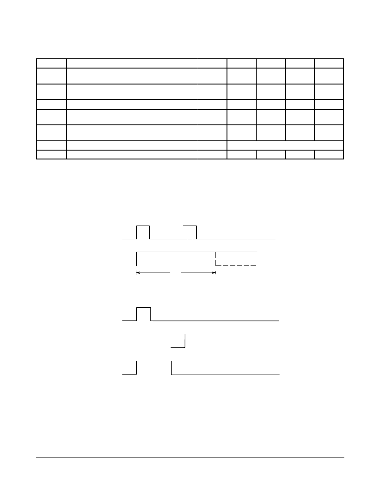
GUARANTEED OPERATING RANGES
Symbol Parameter Min Typ Max Unit
V
CC
T
A
I
OH
I
OL
R
ext
C
ext
R
ext/Cext
Supply Voltage 54
Operating Ambient Temperature Range 54
Output Current — High 54, 74 –0.4 mA
Output Current — Low 54
External Timing Resistance 54
External Capacitance 54, 74 No Restriction
Wiring Capacitance at R
ext/Cext
Terminal 54, 74 50 pF
74
74
74
74
4.5
4.75
–55
0
5.0
5.0
5.0
5.0
25
25
5.5
5.25
125
70
4.0
8.0
180
260
WAVEFORMS
V
°C
mA
kΩ
B INPUT
Q OUTPUT
RETRIGGER
PULSE
t
W
(See Application Data)
OUTPUT WITHOUT RETRIGGER
EXTENDING PULSE WIDTH
B INPUT
CLEAR INPUT CLEAR PULSE
OUTPUT WITHOUT CLEAR PULSE
Q OUTPUT
OVERRIDING THE OUTPUT PULSE
FAST AND LS TTL DATA
5-3
Page 4
SN54/74LS122 • SN54/74LS123
VILI
LOW Volt
V
pg
VOHOutput HIGH Volt
CC
,
OH
,
IN IH
VOLOutput LOW Volt
V
V
V
IIHI
HIGH C
t
ICCP
t
A
V
MAX
PLH
pg y,
C
ext
0
PLH
pg y,
ext
PLH
pg y,
ext
p,
ext
,
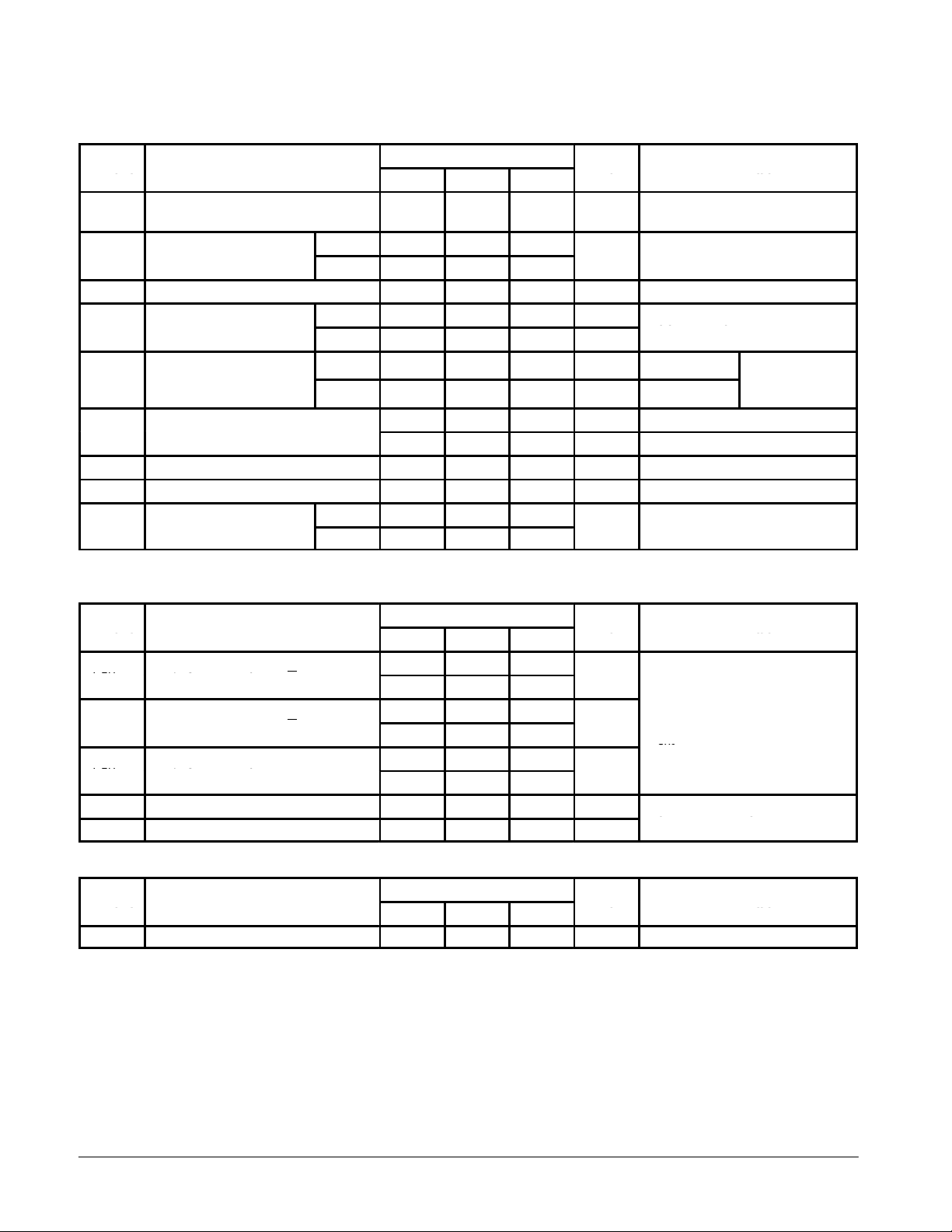
DC CHARACTERISTICS OVER OPERATING TEMPERATURE RANGE (unless otherwise specified)
Limits
Symbol Parameter
V
IH
V
IK
I
IL
I
OS
Note 1: Not more than one output should be shorted at a time, nor for more than 1 second.
Input HIGH Voltage 2.0 V
nput
Input Clamp Diode Voltage –0.65 –1.5 V VCC = MIN, IIN = –18 mA
nput
Input LOW Current –0.4 mA VCC = MAX, VIN = 0.4 V
Short Circuit Current (Note 1) –20 –100 mA VCC = MAX
ower Supply Curren
age
age
age
urren
54 0.7
74 0.8
54 2.5 3.5 V
74 2.7 3.5 V
54, 74 0.25 0.4 V IOL = 4.0 mA
74 0.35 0.5 V IOL = 8.0 mA
LS122 11
LS123 20
Min Typ Max
20 µA VCC = MAX, VIN = 2.7 V
0.1 mA VCC = MAX, VIN = 7.0 V
Unit Test Conditions
Guaranteed Input HIGH Voltage for
All Inputs
Guaranteed Input LOW Voltage for
All Inputs
VCC = MIN, IOH = MAX, VIN = V
or VIL per Truth Table
m
CC
=
IH
VCC = VCC MIN,
=
or
IN
IL
per Truth Table
IH
AC CHARACTERISTICS (T
Symbol Parameter
t
PLH
t
PHL
t
PLH
t
PHL
t
PLH
t
PHL
t
Wmin
tWQ A to B to Q 4.0 4.5 5.0 µs
Propagation Delay, A to Q
Propagation Delay, A to Q
Propagation Delay, B to Q
Propagation Delay, B to Q
Propagation Delay, Clear to Q
Propagation Delay, Clear to Q
A or B to Q 116 200 ns
AC SETUP REQUIREMENTS (T
Symbol Parameter
t
W
Pulse Width 40 ns
= 25°C, VCC = 5.0 V)
A
= 25°C, VCC = 5.0 V)
A
Limits
Min Typ Max
23 33
32 45
23 44
34 56
28 45
20 27
Limits
Min Typ Max
Unit Test Conditions
ns
C
= 0
ext
CL = 15 pF
ns
ns
Unit Test Conditions
R
= 5.0 kΩ
ext
RL = 2.0 kΩ
C
= 1000 pF, R
ext
CL = 15 pF, RL = 2.0 kΩ
= 10 kΩ,
ext
FAST AND LS TTL DATA
5-4
Page 5
SN54/74LS122 • SN54/74LS123
V
CC
0.1
µ
F
/
V
CC
Q
Q
P
out
C
ext
CLR
B2
B1
A2
A1
C
ext
V
RC
R
ext
R
C
LS122
GND
ext
ext
V
V
CC
P
in
51
Ω
V
RC
R
ext
C
ext
C
extRext
CLR
1/2 LS123
B
A
C
ext
GND
V
CC
0.1
µ
F
/
V
CC
Q
Q
P
out
P
in
CC
51
Ω
Figure 1 Figure 2
P
in
P
out
t
W
10
1
µ
ext
0.1
EXTERNAL CAPACITANCE, C ( F)
0.01
0.001
0.3 0.35 0.4 0.45 0.5 0.55
Figure 3
5K ≤ R
K
Figure 4
RETRIGGER
≤ 260K
ext
FAST AND LS TTL DATA
5-5
Page 6
SN54/74LS122 • SN54/74LS123
0.55
VRC = 5 V
C
= 1000 pF
ext
0.5
–55
°
°
0
25°C
70°C
125
°
100000
C
C
C
V
CC
CC
K
0.45
0.4
0.35
4.5 5 5.5
Figure 5. K versus V
0.55
0.5
VCC = 5 V
C
= 1000 pF
ext
–55°C
0°C
K
0.45
0.4
0.35
4.5 5 5.5
70°C
125°C
V
RC
Figure 6. K versus V
RC
25°C
0.55
C
= 1000 pF
ext
0.5
K
0.45
0.4
0.35
4.5 5 5.5
–55
°
C
°
C
0
°
C
25
70
°
C
125°C
VCC = V
RC
Figure 7. K versus VCC and V
RC
10000
1000
, OUTPUT PULSE WIDTH (ns)
W
t
100
10
1 10 100 1000
R
ext
R
ext
= 260 k
= 160 k
Ω
Ω
R
= 80 k
Ω
ext
R
= 40 k
Ω
ext
R
= 20 k
Ω
ext
R
= 10 k
Ω
ext
R
= 5 k
Ω
ext
C
, EXTERNAL TIMING CAPACITANCE (pF)
ext
Figure 8
FAST AND LS TTL DATA
5-6
Page 7
0.65
SN54/74LS122 • SN54/74LS123
C
= 200 pF
ext
–55
°
C
0.6
K
0.55
0.5
4.5 4.75 5 5.25 5.5
25
70
125
0°C
°
°
°
C
C
C
VCC VOLTS
Figure 9
R
PIN 7
OR 15
C
PIN 6
OR 14
ext
ext
Figure 10. LS123 Remote Trimming Circuit
FAST AND LS TTL DATA
5-7
V
CC
R
ext
REMOTE
Page 8
SN54/74LS122 • SN54/74LS123
PIN 9
PIN 13
PIN 11
OPEN
C
ext
R
ext
V
CC
R
ext
REMOTE
Figure 11. LS122 Remote Trimming Circuit Without R
PIN 9
PIN 13
PIN 11
Figure 12. LS122 Remote Trimming Circuit with R
ext
V
CC
R
ext
REMOTE
int
FAST AND LS TTL DATA
5-8
 Loading...