

Page 1
DUAL JK NEGATIVE
OPERATING MODE
EDGE-TRIGGERED FLIP-FLOP
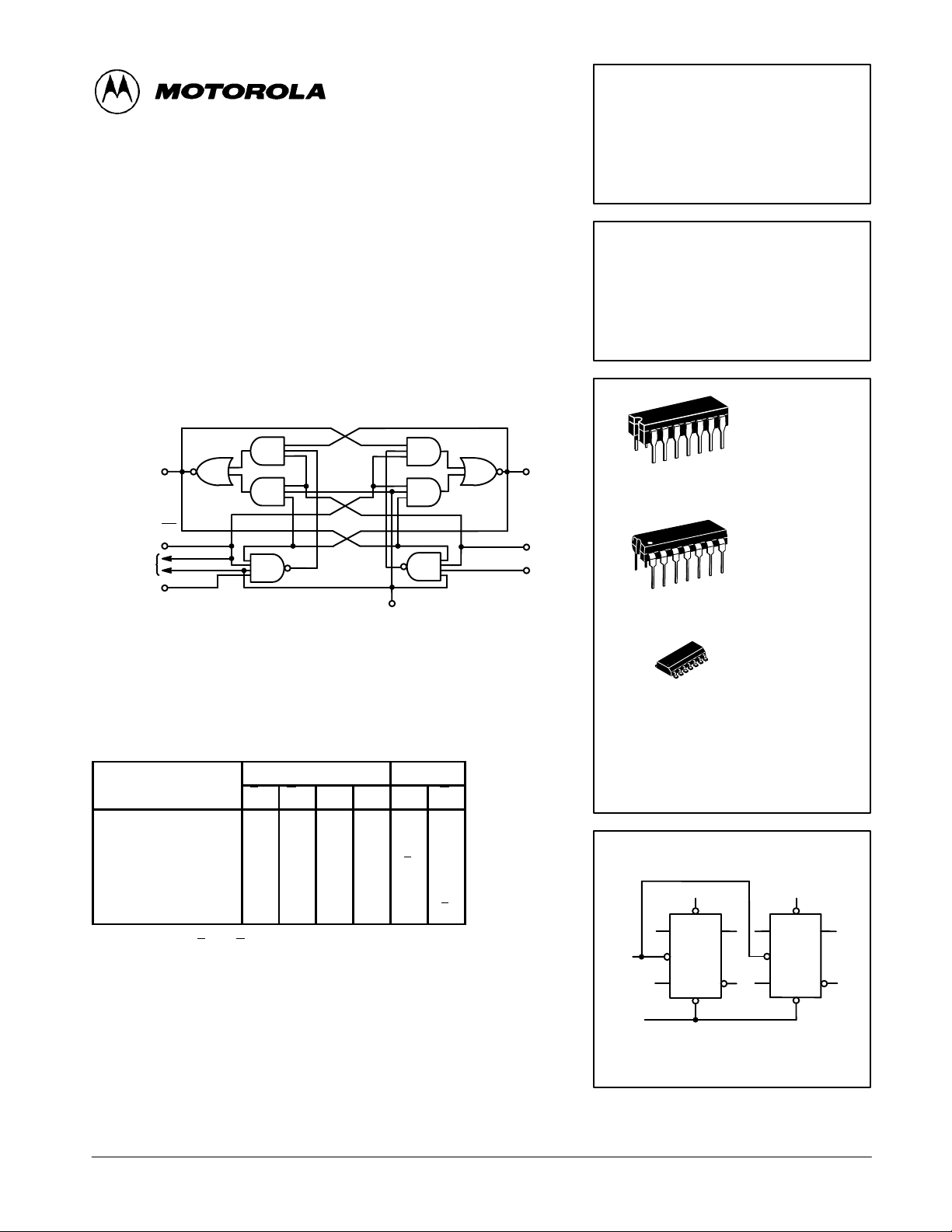
The SN54/74LS1 14A of fers common clock and common clear inputs and
individual J, K, and set inputs. These monolithic dual flip-flops are designed
so that when the clock goes HIGH, the inputs are enabled and data will be
accepted. The logic level of the J and K inputs may be allowed to change when
the clock pulse is HIGH and the bistable will perform according to the truth
table as long as minimum set-up times are observed. Input data is transferred
to the outputs on the negative-going edge of the clock pulse.
LOGIC DIAGRAM (Each Flip-Flop)
Q
5(9)
6(8)
Q
SN54/74LS1 14A
DUAL JK NEGATIVE
EDGE-TRIGGERED FLIP-FLOP
LOW POWER SCHOTTKY
J SUFFIX
CERAMIC
14
1
CASE 632-08
CLEAR (C
TO
OTHER
FLIP-FLOP
J
3(11)
)
D
13
CLOCK (CP)
MODE SELECT — TRUTH TABLE
INPUTS OUTPUTS
SDC
Set
Reset (Clear)
*Undetermined
Toggle
Load “0” (Reset)
Load “1” (Set)
Hold
* Both outputs will be HIGH while both S
are unpredictable if S
H, h = HIGH Voltage Level
L, I = LOW Voltage Level
X = Don’t Care
l, h (q) = Lower case letters indicate the state of the referenced input (or output)
l, h (q) = one set-up time prior to the HIGH to LOW clock transition.
D
L
H
L
H
H
H
H
and CD go HIGH simultaneously.
D
J K Q Q
D
H
X
X
H
L
X
L
H
H
H
H
and CD are LOW, but the output states
X
X
X
h
h
l
h
h
l
l
l
L
L
H
H
H
q
q
H
L
L
H
q
q
4(10)
SET (SD)
K
2(12)
14
1
14
1
CASE 646-06
CASE 751A-02
ORDERING INFORMATION
SN54LSXXXJ Ceramic
SN74LSXXXN Plastic
SN74LSXXXD SOIC
LOGIC SYMBOL
4
13
S
D
J
CP
K
Q
Q
C
D
3
2
1
11
5
12
6
N SUFFIX
PLASTIC
D SUFFIX
SOIC
10
S
D
Q
J
CP
Q
K
C
D
9
8
VCC = PIN 14
GND = PIN 7
FAST AND LS TTL DAT A
5-1
Page 2
SN54/74LS114A
VILI
LOW Volt
V
pg
54
2.5
3.5
V
VOHOutput HIGH Voltage
CC
,
OH
,
IN IH
VOLOutput LOW Volt
V
V
V
IIHI
HIGH C
t
PLH
pg y, ,
C
L
pF
V
V
GUARANTEED OPERATING RANGES
Symbol Parameter Min Typ Max Unit
V
CC
T
A
I
OH
I
OL
DC CHARACTERISTICS OVER OPERATING TEMPERATURE RANGE (unless otherwise specified)
Symbol Parameter
V
IH
V
IK
I
IL
I
OS
I
CC
Note 1: Not more than one output should be shorted at a time, nor for more than 1 second.
AC CHARACTERISTICS (T
Symbol Parameter
f
MAX
t
PLH
t
PHL
AC SETUP REQUIREMENTS (T
Symbol Parameter
t
W
t
W
t
s
t
h
Supply Voltage 54
Operating Ambient Temperature Range 54
Output Current — High 54, 74 –0.4 mA
Output Current — Low 54
Limits
Min Typ Max
Input HIGH Voltage 2.0 V
nput
Input Clamp Diode Voltage –0.65 –1.5 V VCC = MIN, IIN = –18 mA
nput
Input LOW Current
Output Short Circuit Current (Note 1) –20 –100 mA VCC = MAX
Power Supply Current 6.0 mA VCC = MAX
Maximum Clock Frequency 30 45 MHz
Propagation Delay, Clock,
Clear, Set to Output
Clock Pulse Width High 20 ns
Clear, Set Pulse Width 25 ns
Setup Time 20 ns
Hold Time 0 ns
age
age
J, K
Set
Clear
urren
A
Clock
J, K
Set
Clear
Clock
J, K
Set
Clear, Clock
= 25°C, VCC = 5.0 V)
= 25°C, VCC = 5.0 V)
A
54 0.7
74 0.8
74 2.7 3.5 V
54, 74 0.25 0.4 V IOL = 4.0 mA
74 0.35 0.5 V IOL = 8.0 mA
Limits
Min Typ Max
15 20 ns
15 20 ns
Limits
Min Typ Max
74
74
74
20
60
120
160
0.1
0.3
0.6
0.8
–0.4
–0.8
–1.6
4.5
4.75
–55
0
Unit Test Conditions
Guaranteed Input HIGH Voltage for
All Inputs
Guaranteed Input LOW Voltage for
All Inputs
VCC = MIN, IOH = MAX, VIN = V
or VIL per Truth Table
µA VCC = MAX, VIN = 2.7 V
mA VCC = MAX, VIN = 7.0 V
mA VCC = MAX, VIN = 0.4 V
Unit Test Conditions
Unit Test Conditions
5.0
5.0
25
25
5.5
5.25
125
70
4.0
8.0
VCC = VCC MIN,
=
IN
IL
per Truth Table
VCC = 5.0 V
= 15
C
= 15
F
= 5.0
CC
or
IH
IH
V
°C
mA
FAST AND LS TTL DATA
5-2
 Loading...