

Page 1
SMTHDTxx
ApplicationSpecific Discretes
A.S.D.
FEATURES
UND IRECTIONA L CROWBA R
PROTECTION.
PEAKPULSECURRENT:
IPP= 75A , 10/1000µs.
HOLDINGCURRENT= 150mA.
BREAKDOWNVOLTAGE:
SMTHDT58= 58V.
SMTHDT80= 80V.
SMTHDT120= 120V.
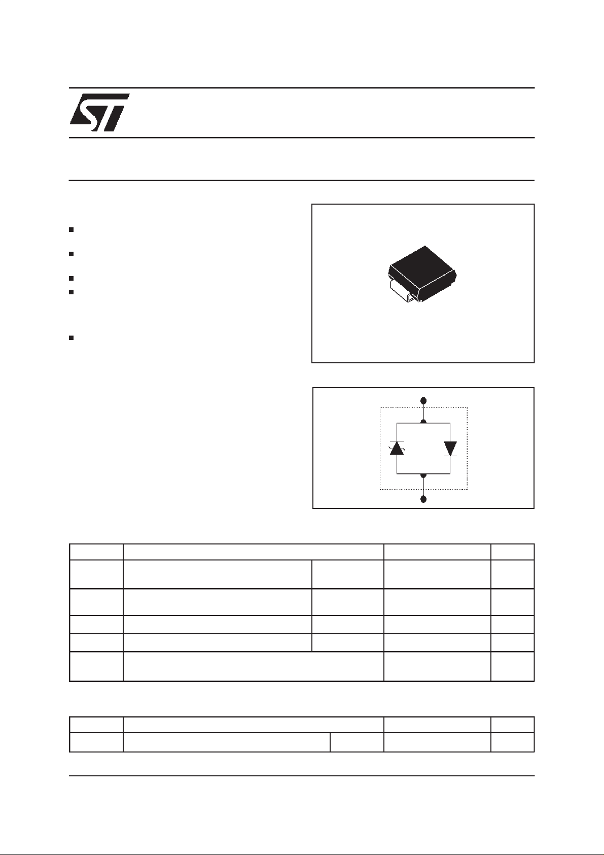
PACKAGES:
SMTHDTxx= SURFACEMOUNTPACKAGE.
DESCRIPTION:TRIBALANCED PROTECTION
Dedicated protection devices for ISDN LINE
CARDand high speeddata telecomlines.
Usedwiththerecommendedconfigurationusing
3 components,theywill provide=
-Dualbidirectionnalprotection,with fixed
breakdownvoltage in bothcommonand
differentialmodes.
-Low capacitancesfromlines to ground.
-Verygood capacitancebalance: ∆C= 30 pF.
TM
DISCRETE SOLUTION FOR ISDN PROTECTION
TRISIL
SMC
FUNCTIONAL DIAGRAM.
A
K
ABSOLUTE RATINGS(limitingvalues) (-40°C ≤ T
Symbol Parameter Value Unit
I
PP
I
TSM
di/dt
dv/dt
T
stg
T
THERMAL RESISTANCES
Symbol Parameter Value Unit
(j-l)
R
th
April 1999 - Ed: 1A
Peakpulse current
Non repetitive surge peak on-state
current
Criticalrateof riseof on-statecurrent
Criticalrateof riseof off-statevoltage
Storageand operatingjunctiontemperaturerange
j
Junction-leadsThermalResistance
≤ +85°C)
amb
10/1000µs
8/20 µs
tp= 20ms 30 A
Nonrepetitive 100 A/µs
67%V
BR
SMC 200 °C/W
75
150
5KV/µs
- 40 to + 150
+ 150
A
°C
°C
1/6
Page 2
SMTHDTxx
Symbol Parameter
V
RM
V
BR
V
BO
I
H
V
T
V
F
I
BO
I
PP
V
F
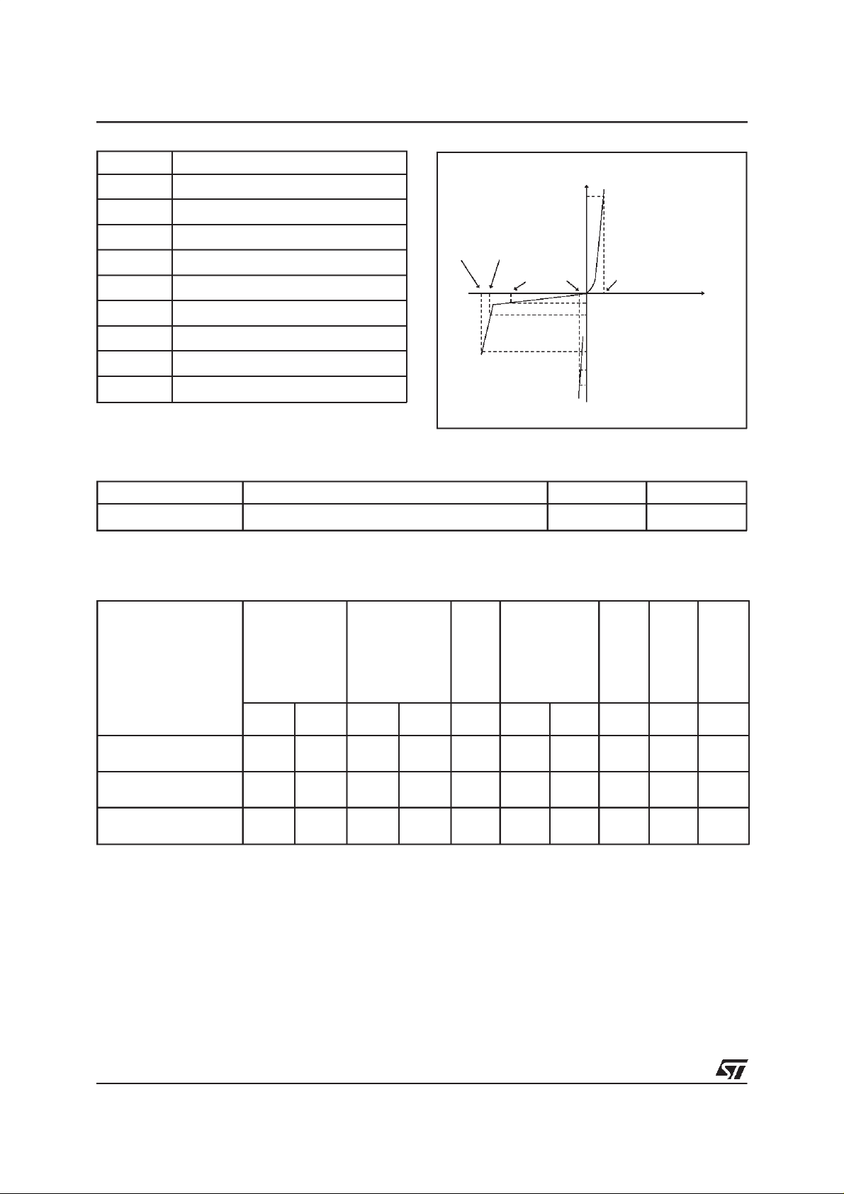
Stand-offvoltage
Breakdownvoltage
Breakovervoltage
Holdingcurrent
On-statevoltage
ForwardVoltageDrop
Breakovercurrent
Peak pulsecurrent
ForwardVoltageDrop
VV
BOVBR
V
RM
PARAMETERSRELATED TO THE DIODE.
Parameter Test conditions Value Unit
V
F
IF= 5A, TP=500µs5V
I
I
F
I
RM
1mA
I
H
I
BO
I
T
I
PP
V
V
T
F
V
PARAMETERSRELATED TO THE PROTECTIONTRISIL.
Types IR@V
RM
V
BR @IR
V
BO
I
BO
IH VT C
max min max min max min max max
note1 note1 note1 note1 note2 note3
µA V V mA V mA mA mA V pF
SMTHDT58 10 56 58 1 80 150 800 150 5 400
SMTHDT80 10 68 80 1 120 150 800 150 5 250
SMTHDT120 10 102 120 1 180 150 800 150 5 200
Allparameters tested at 25 °C, except whereindicated.
Note 1: Seethe reference test circuitfor I
Note 2: Squarepulse Tp = 500µs-I
Note 3: V
= 1V,F =1MHz.
R
T
and VBOparameters.
H,IBO
= 5A.
2/6
Page 3

REFERENCETESTCIRCUIT FOR IH,IBOandVBOparameters:
Tp = 20ms
Auto
Transfor mer
220V/2A
static
relay.
K
V
out
220V
Transfor mer
220V/ 800V
5A
I,I
BO H
measure
TESTPROCEDURE :
PulseTest duration(Tp = 20ms):
- For Bidirectionaldevices= SwitchK isclosed
- For Unidirectionaldevices = SwitchKis open.
Selection
V
OUT
- DevicewithV
-V
- Devicewith V
-V
BR
OUT
BR
OUT
≤ 150 Volt
= 250V
≥ 150 Volt
= 480V
RMS,R1
RMS,R2
=140Ω.
= 240 Ω.
R1
140
R2
240
D.U.T
V
BO
measure
SMTHDTxx
FUNCTIONALHOLDING CURRENT (I
Vbat = 48V
This isa GO-NOGOTestwhich allowsto confirmthe holding current(IH) levelina functionaltest
circuit.This test can be performedif thereferencetest circuitcan’tbeimplemented.
TESTPROCEDURE :
1) Adjustthe current level at the I
2) Firethe D.U.Twith a surgeCurrent: Ipp = 25A , 10/700µs.
3) TheD.U.Twill comebackto theOFF-Statewithin a duration of 50 ms max.
) TEST CIRCUIT= GO- NOGOTEST.
H
25 15
Switch
A
20
D.U.T
220nF
50
K
Surge Generator
10/700 sec
Vp =1KV / Ipp = 25A
valueby shortcircuitingthe AKof the D.U.T.
H
F
Vp =
1KV
3/6
Page 4

SMTHDTxx
APPLICATIONNOTE
ISDN PROTECTION.
LINE A
A
3.TPUxx
or
3.SMTHDTxx
B
LINE B
TRIPOLE PROTECTION FULL BALANCED PROTECTION
RECOMMENDEDCONFIGURATION FOR TRIBALANCED PROTECTION MODE.
CAPACITANCECHARACTERISTICS
Type CONFIGURATION C
GND
LINE A
LINE B
A
pF
C
C
pF
C
A
GND
C
B
B
∆C
pF
LINEA LINE B Max Max Max
SMTHDT58 48 0 80 60 30
SMTHDT80 56 0 70 50 30
SMTHDT120 110 0 70 50 30
4/6
Page 5

APPLICATIONNOTE
DiscreteISDN Protectionsolution
LINE A
3 TPUxx
3 SMTHDTxx
LINE B
or
SMTHDTxx
A
GND
TRANSFORMER
B
EQUIVALENT PROTECTIONFUNCTION
U InterfaceProtection
A
TPUxx
B
This topologyassumes the samebreakdown voltagelevel in positive and negative for differential orcommonmodesurge.
RorPTC
GND
RorPTC
S InterfaceProtection
A
TPUxx
B
A
TPUxx
B
GND
GND
RorPTC
RorPTC
RorPTC
RorPTC
5/6
Page 6

SMTHDTxx
ORDERCODE
SM THDT 80
Surface
Mount
PACKAGEMECHANICAL DATA
SMC
E1
E
C
E2
Unidirectionnal
D
L
MARKING
Package Type Marking
SMC
SMTHDT58
SMTHDT80
SMTHDT120
W01
W03
W05
Breakdown
Voltage
REF. DIMENSIONS
Millimeters Inches
Min. Max. Min. Max.
A1 1.90 2.45 0.075 0.096
A2 0.05 0.20 0.002 0.008
b 2.90 3.2 0.114 0.126
c 0.15 0.41 0.006 0.016
E 7.75 8.15 0.305 0.321
A1
E1 6.60 7.15 0.260 0.281
E2 4.40 4.70 0.173 0.185
A2
b
D 5.55 6.25 0.218 0.246
L 0.75 1.60 0.030 0.063
FOOTPRINT DIMENSIONS(in millimeters)
3.3
2.0 4.2 2.0
Informationfurnished is believed tobe accurateand reliable. However, STMicroelectronics assumesno responsibilityfor theconsequences of
use of such information nor forany infringementof patentsor otherrightsof thirdparties which mayresult fromitsuse. No license is granted by
implication or otherwise under any patent or patent rights of STMicroelectronics. Specifications mentioned in this publication are subject to
change without notice. This publication supersedes and replacesall informationpreviously supplied.
STMicroelectronics products are not authorized for use as critical components in life support devices or systems withoutexpress writtenapproval of STMicroelectronics.
The ST logo is a registered trademarkof STMicroelectronics
1999 STMicroelectronics - Printed inItaly - Allrights reserved.
STMicroelectronics GROUP OF COMPANIES
Australia -Brazil - China - Finland - France - Germany - Hong Kong - India - Italy - Japan - Malaysia
Malta -Morocco - Singapore - Spain - Sweden - Switzerland - United Kingdom - U.S.A.
http://www.st.com
6/6
 Loading...