

Datasheet SMP1307-001, SMP1307-004, SMP1307-005, SMP1307-011, SMP1307-027 Datasheet (ALPHA)
Page 1
Alpha Industries, Inc. [781] 935-5150 • Fax [617] 824-4579 • Email sales@alphaind.com • www.alphaind.com 1
Specifications subject to change without notice. 1/01A
Very Low Distortion Attenuator
Plastic Packaged PIN Diodes
Features
■ Low Distortion Design
■ Frequency Range from HF to > 2 GHz
■ Designed for CATV AGC Applications
■ Designed for High Volume Wireless
Applications
Description
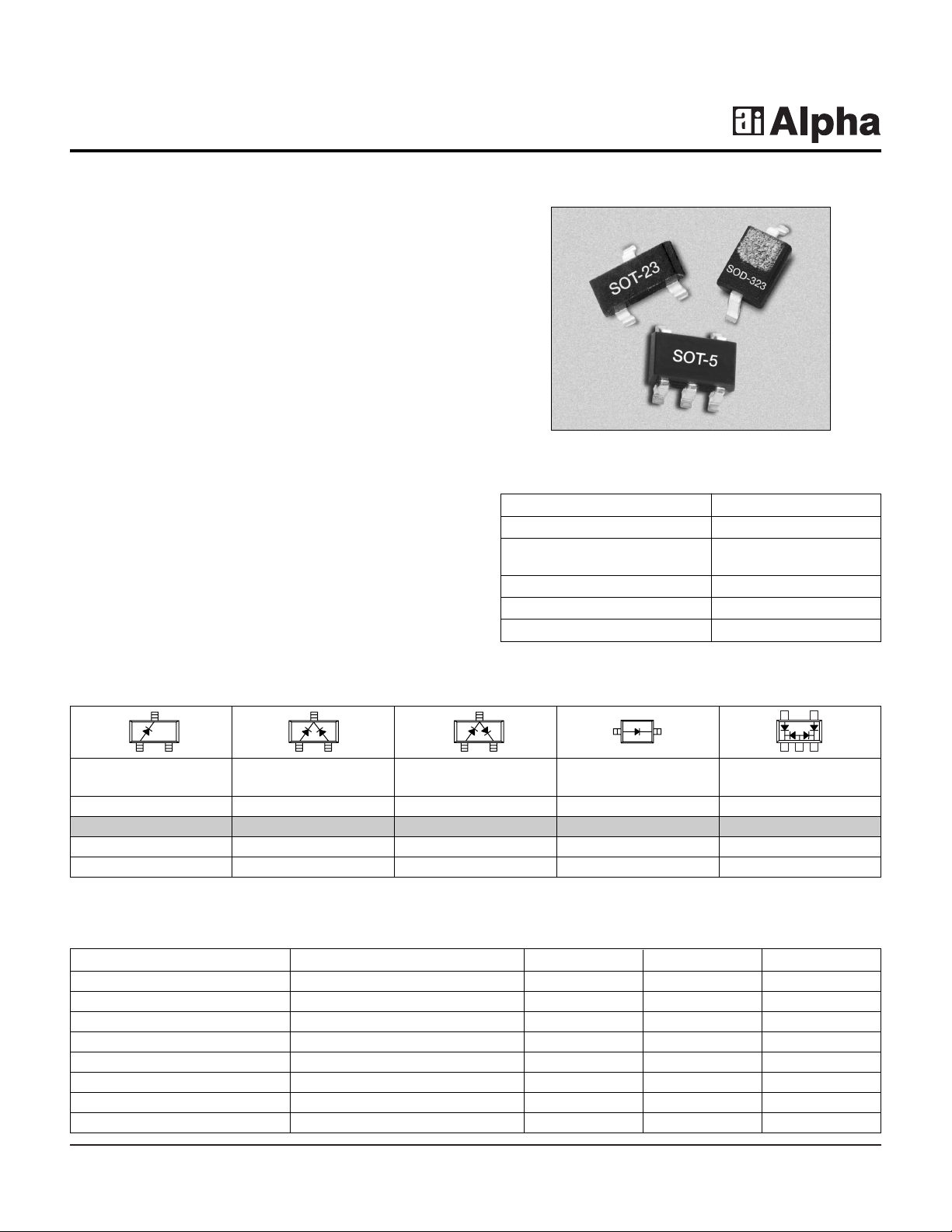
The SMP1307 series of plastic packaged, surface
mountable, low capacitance (0.3 pF) silicon PIN diodes
are designed for use in attenuator applications from 5 MHz
to beyond 2 GHz.The thick 175 µm I region of these PIN
diodes makes them very attractive for use in very low
distortion PI and TEE attenuators commonly used in TV
distribution applications. The 1.5 µS typical carrier
lifetime of these diodes results in resistance of 100 Ω
maximum at 1 mA and 10 Ωmaximum at 10 mA.Av ailable
in a selection of plastic packages, as a single diode in the
small footprint SOD-323, and in a variety of configurations
in the SOT-23.Also availab le in a SO T-5 (SMP1307-027)
package as a four diode arra y designed f or insertion in the
commonly used 4 diode PI attenuator circuit.
SMP1307 Series
Characteristic Value
Reverse Voltage (VR) 200 V
Power Dissipation @ 25°C Lead 250 mW
Temperature (PD)
Storage Temperature (TST) -65°C to +150°C
Operating Temperature (TOP) -65°C to +150°C
ESD Human Body Model Class 1C
Absolute Maximum Ratings
Single Common Series Pair Single PI
Cathode
Marking: PJ1 Marking: PJ3 Marking: PJ2 Marking: PJM
SOT-23 SOT-23 SOT-23 SOD-323 SOT-5
♦ SMP1307-001 ♦ SMP1307-004 ♦ SMP1307-005 ♦ SMP1307-011 ♦ SMP1307-027
LS= 1.5 nH LS= 1.5 nH LS= 1.5 nH LS= 1.5 nH
♦ Available through distribution.
Parameter Condition Typ. Max. Unit
Reverse Current (IR)V
R
= 200 V 10 µA
Capacitance (CT) F = 1 MHz, V = 30 V 0.30 pF
Resistance (RS) F = 100 MHz, I = 1 mA 75 100 Ω
Resistance (RS) F = 100 MHz, I = 10 mA 15 Ω
Resistance (RS) F = 100 MHz, I = 100 mA 3.0 Ω
Forward Voltage (VF) IF = 10 mA 0.85 V
Carrier Lifetime (TI) IF = 10 mA 1.5 µS
I Region Width 175 µm
Electrical Specifications at 25°C
Page 2
2 Alpha Industries, Inc. [781] 935-5150 • Fax [617] 824-4579 • Email sales@alphaind.com • www.alphaind.com
Specifications subject to change without notice. 1/01A
Very Low Distortion Attenuator Plastic Packaged PIN Diodes SMP1307 Series
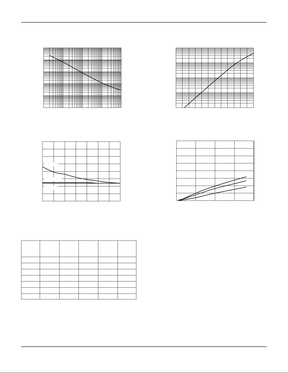
Series Resistance vs. Current @ 100 MHz
0.01 0.1 1 10 100
Forward Current (mA)
Series Resistance (Ω)
0.1
1
10
100
1000
10000
01251020 10050
Capacitance vs. Reverse Voltage
0
0.2
0.4
0.6
0.1
0.3
0.5
0.7
0.8
Reverse Voltage (V)
Capacitance (pF)
100 MHz
1 MHZ
1 GHz
400 500 600 700 800 900 1000
DC Characteristic
0.01
0.1
1
10
100
Forward Voltage (mV)
Forward Current (mA)
0 500 1000 1500 2000
Conductance vs. Frequency
and Reverse Voltage
Frequency (MHz)
Conductance (µS)
0
50
100
150
200
250
300
350
400
0 V
10 V
40 V
Typical Performance Data
RRRRR
I
F
-55°C -15°C +25°C +65°C +100°C
(mA) (ΩΩ)(
ΩΩ
)(
ΩΩ
)(
ΩΩ
)(
ΩΩ
)
0.02 2386.0 2360.0 2546.0 2520.0 2440.0
0.10 572.0 598.0 632.0 633.0 639.0
0.30 203.0 219.0 236.0 239.0 242.0
1.00 66.1 71.2 79.3 83.6 85.4
10.00 9.1 10.0 10.9 12.2 12.9
20.00 5.6 6.0 6.6 7.4 7.8
100.00 2.2 2.4 2.6 3.0 3.2
Resistance vs. Temperature @ 100 MHz
Page 3

Very Low Distortion Attenuator Plastic Packaged PIN Diodes SMP1307 Series
Alpha Industries, Inc. [781] 935-5150 • Fax [617] 824-4579 • Email sales@alphaind.com • www.alphaind.com 3
Specifications subject to change without notice. 1/01A
SMP1307-027 4 Diode PI Attenuator
The SMP1307-027 employs 4 PIN diode junctions in a
5-lead SOT package. It is configured for ease of
insertion in the PI attenuator circuit commonly used for
broadband TV distribution systems , cov ering a frequency
range from 5 MHz to beyond 1 GHz.
A broadband attenuator was designed using the
SMP1307-027 showing good performance to 2 GHz.The
attenuator was evaluated with a 50 Ω source and load
impedance. The following figure shows the circuit
diagram and measured performance.
C
1
10,000 pF
C
2
10,000 pF
C
4
10,000 pF
C
5
10,000 pF
C
6
10,000 pF
C
3
10,000 pF
R
2
1 k
R
1
1 k
R
3
1 k
R
5
560
R
4
1 k
R
6
560
D
1
D
2
D
3
D
4
V
TUNE
0–20 V
V
REF
5 V
RF
Output
RF
Input
A 4 diode PI attenuator utilizing individual SMP1307-011 PIN diodes is described in the “A Wideband General Purpose PIN Diode Attenuator”Application Note.
D1–D4SMP1307-027
-50
-40
-30
-20
-10
0
0 0.5 1.0 1.5 2.0
Frequency (GHz)
Attenuation (dB)
V
CTL
= 20 V
V
CTL
= 15 V
V
CTL
= 10 V
V
CTL
= 5 V
V
CTL
= 0 V
SMP1307-027 Attenuation vs. Frequency
45
123
Page 4

4 Alpha Industries, Inc. [781] 935-5150 • Fax [617] 824-4579 • Email sales@alphaind.com • www.alphaind.com
Specifications subject to change without notice. 1/01A
Very Low Distortion Attenuator Plastic Packaged PIN Diodes SMP1307 Series
SOD-323
0.090 (2.30 mm) MIN.
0.108 (2.74 mm) MAX.
0.045 (1.15 mm) MIN.
0.053 (1.35 mm) MAX.
0.050
(1.25 mm) MAX.
0.006
(0.15 mm) TYP.
0.008 (0.20 mm) NOM.
0.004 (0.10 mm) MAX.
0.010 (0.25 mm) MIN.
0.010
(0.25 mm) MIN.
0.016
(0.40 mm) MAX.
0.063 (1.60 mm) MIN.
0.071 (1.80 mm) MAX.
CATHODE
INDICATOR
21
SOT-23
3
2
1
0.035 (0.89 mm) MIN.
0.044 (1.12 mm) MAX.
0.0005 (0.01 mm) MIN.
0.004 (0.10 mm) MAX.
0.012 (0.30 mm) MIN.
0.020 (0.50 mm) MAX.
0.003 (0.080 mm) MIN.
0.008 (0.20 mm) MAX.
8˚ MAX.
0.022 (0.55 mm) REF.
0.110 (2.80 mm) MIN.
0.120 (3.04 mm) MAX.
0.083 (2.10 mm) MIN.
0.104 (2.64 mm) MAX.
0.037 (0.95 mm) REF.
0.047 (1.20 mm) MIN.
0.055 (1.40 mm) MAX.
0.076 (1.92 mm) REF.
0.020 (0.51 mm) REF.
SOT-5
0.110 (2.79 mm) MIN.
0.118 (3.00 mm) MAX.
0.014
(0.36 mm)
MIN.
0.020
(0.51 mm)
MAX.
0.102
(2.59 mm)
MIN.
0.118
(3.00 mm)
MAX.
0.060
(1.52 mm)
MIN.
0.069
(1.75 mm)
MAX.
0.037
(0.94 mm) REF.
0.037
(0.94 mm) REF.
123
45
0.004 (0.10 mm) MIN.
0.024 (0.61 mm) MAX.
0.134
(3.4 mm)
10˚ MAX.
0.035
(0.89 mm)
MIN.
0.057
(1.49 mm)
MAX.
0.000 (0.00 mm) MIN.
0.006 (0.15 mm) MAX.
0.035 (0.89 mm) MIN.
0.051 (1.30 mm) MAX.
 Loading...