

Page 1

1
Characteristics subject to change without notice 2057 1.x 8/16/01
SMH4044
SUMMIT
MICROELECTRONICS, Inc.
Preliminary
©SUMMIT MICROELECTRONICS, Inc., 2001 • 300 Orchard City Dr., Suite 131 • Campbell, CA 95008 • Phone 408-378-6461 • FAX 408-378-6586 • www.summitmicro.com
!!
!!
! IPMI Implementation
""
""
" IPMB Interface
""
""
" Software Controlled Power-Up/-Down
""
""
" Status Reporting: 5V, 3.3V, V1, V2, Healthy,
Signal Valid, Reset
""
""
" 2k-Bit E2PROM Memory
!!
!!
! Full Voltage Control for Hot Swap Applications
""
""
" Detect, Monitors and Controls up to 4 inde-
pendent supplies
!!
!!
! 14V High Side Driver Generation Allows use of
Low On Resistance N-Channel FETs
Compact PCI Hot-Swap Controller
With IPMI Support
FEATURES
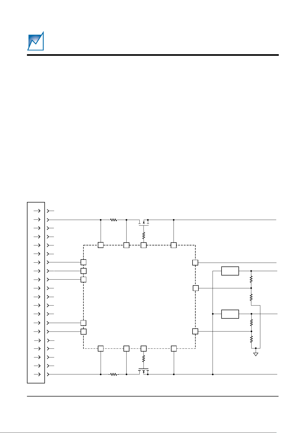
SIMPLIFIED APPLICATION DRAWING
!!
!!
! Under-Voltage Lockout
!!
!!
! Electronic Circuit Breakers
""
""
" Programmable Over-current Levels
!!
!!
! Card Insertion Detection
!!
!!
! Card Voltage Sequencing
!!
!!
! Flexible Reset Control
""
""
" Low Voltage Resets
""
""
" Host Reset Filtering
""
""
" Soft Reset
!!
!!
! Adjustable Power On Slew Rate
Simplified Application Drawing — Triple Voltage Hot Swap (12V, 5V, 3.3V)
1N4148
VCC
HST_
3V_MON
CARD_3V_MON
CARD_5V_MON
SGNL_VLD#
HEALTHY#
DRVREN#
VGATE5
VGATE3
GND
BD_SEL2#
BD_SEL1#
MONITOR1
MONITOR 2
CBI_3
CBI_5
LOCAL_PCI_RST
SMH4044
12V
5V
3.3V
10Ω
4.7kΩ
0.33µF
330kΩ
0.1µF
12V
5V
3.3V
CompactPCI
Backplane
2057 SAD-A
IPMB_SDA
IPMB_SCL
GAO
GA1
GA2
SDA
SCL
A0
A1
A2
26
27
42
44
7
11
41
6
12
20
16
15
18
19
35
36
30
29
33
34
40
45
Page 2

2
SMH4044
2057 1.x 8/16/01
SUMMIT MICROELECTRONICS, Inc.
Preliminary
Simplified Application Drawing — Triple Voltage Hot Swap (5V, 3.3V, 1.8V)
DESCRIPTION
The SMH4044 is a fully integrated hot swap controller that
provides complete power control for add-in cards ranging
in use for basic hot swap systems to high availability
systems. It detects proper insertion of the card and
senses valid supply voltage levels at the backplane.
Utilizing external low on-resistance N-channel MOSFETs, card power is ramped by two high-side driver
outputs that are slew-rate limited at 250V/s.
The SMH4044 continuously monitors the host supplies,
the add-in card supplies and the add-in card currents. If
the SMH4044 detects the current is higher than the
programmed value it will shut down the MOSFETs and
issue a fault status to the host.
The internal 256 × 8 E
2
PROM can be used as configuration memory for the individual card or as general purpose
memory.
Programming of configuration, control and calibration
values by the user can be simplified with the interface
adapter and Windows GUI software obtainable from
Summit Microelectronics.
VCC
HST_3V_MON
CARD_3V_MON
CARD_5V_MON
SGNL_VLD#
HEALTHY#
VGATE5
VGATE3
GND
BD_SEL2#
BD_SEL1#
MONITOR1
MONITOR 2
CBI_3
CBI_5
LOCAL_PCI_RST
SMH4044
1.8V
5V
3.3V
1.8V
5V
3.3V
CompactPCI
Backplane
2057 SAD-B
42
44
41
6
20
16
15
18
19
35
36
30
29
33
34
40
Page 3
3
2057 1.x 8/16/01
SMH4044
SUMMIT MICROELECTRONICS, Inc.
Preliminary
Simplified Application Drawing — Hot Swap with PUP LDO Sensing
VCC
HST_3V_MON
CARD_3V_MON
CARD_5V_MON
SGNL_VLD#
HEALTHY#
VGATE5
VGATE3
GND
BD_SEL2#
BD_SEL1#
MONITOR 2
CBI_3
CBI_5
LOCAL_PCI_RST
SMH4044
5V
3.3V
5V
3.3V
CompactPCI
Backplane
2057 SAD-C
MONITOR 1
LDO
LDO
2.8V
1.8V
42
44
41
6
20
16
15
18
19
35
36
30
29
33
34
40
Page 4
4
SMH4044
2057 1.x 8/16/01
SUMMIT MICROELECTRONICS, Inc.
Preliminary
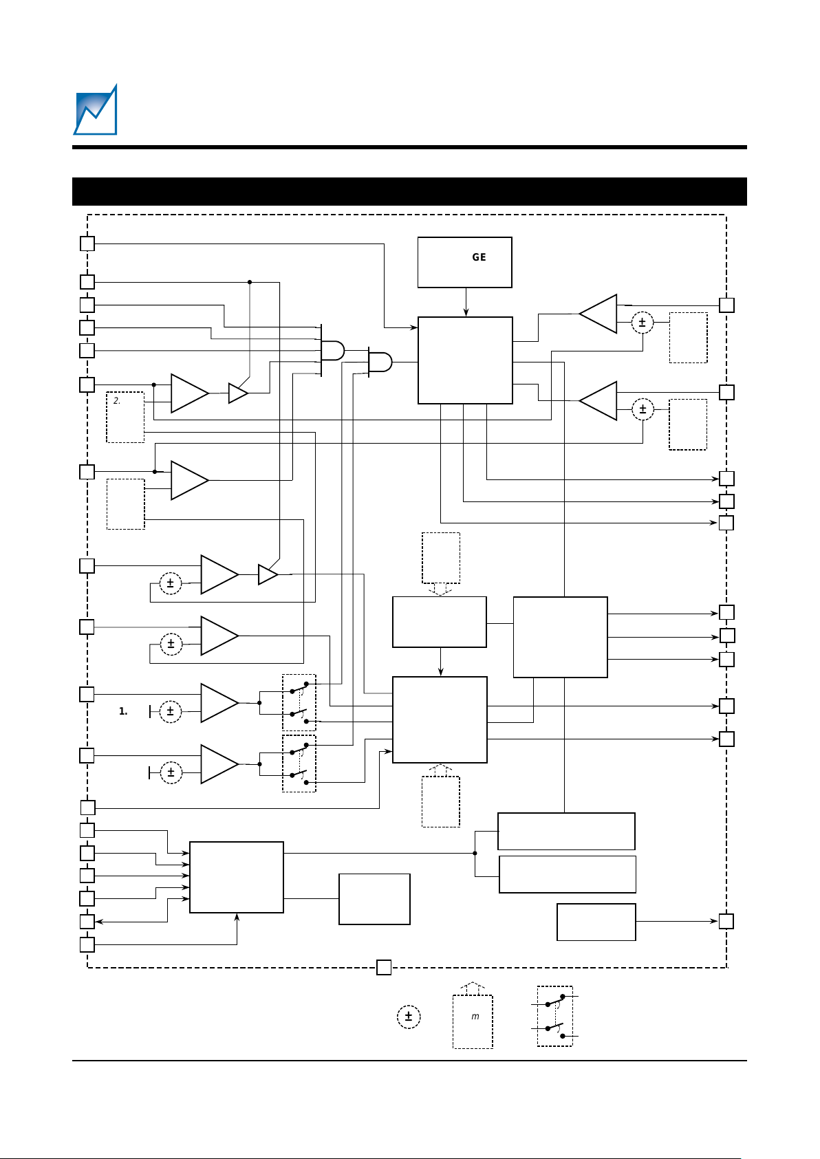
FUNCTIONAL BLOCK DIAGRAM
A0
A1
A2
SCL
SDA
PWR_EN
+
–
VCC
HST_3V_MON
+
–
CARD_3V_MON
CARD_5V_MON
LOCAL_PCI_RST
LOCAL_PCI_RST#
ISLEW
SGNL_VLD#
HEALTHY#
DRVREN#
FAULT#
VGATE5
VGATE3
1VREF
GND
BD_SEL2#
BD_SEL1#
±
±
2.65V
2.80V
2.95V
3.10V
4.625V
4.375V
+
–
+
–
PCI_RST#
+
–
MONITOR1
MONITOR 2
±
±
+
–
1.25V
1.25V
VSEL
RESET
CONTROLLER
25ms
50ms
100ms
200ms
3.2s
1.6s
0.8s
Off
WATCHDOG
TIMER
CS#
I2C
INTERFACE
+
–
CBI_3
CBI_5
+
–
25mV
50mV
75mV
125mV
25mV
50mV
75mV
125mV
±
±
CHARGE
PUMP
SLEW
RATE
CONTROLLER
CONTROL REGISTER
STATUS REGISTER
4K E
2
PROM
16
15
4
33
30
21
40
6
7
11
12
27
26
32
29
8
20
19
45
1
2
34
41
36
44
46
3
18
42
35
BANDGAP
CONTROL
LOGIC
2057 BD
±
25ms
50ms
100ms
200ms
Programmable Functions
Page 5
5
2057 1.x 8/16/01
SMH4044
SUMMIT MICROELECTRONICS, Inc.
Preliminary
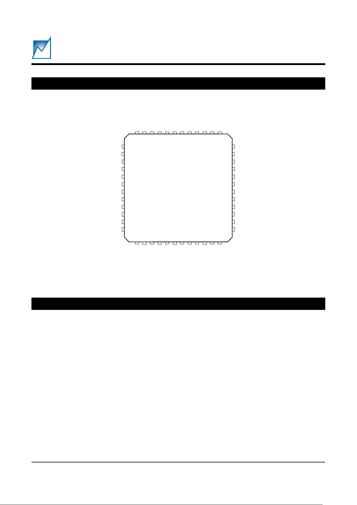
PIN CONFIGURATION
PIN DESCRIPTIONS
A0, A1, A2 (7, 11, 12)
Address inputs 0, 1 and 2 are used to set the three-bit
device address of the memory array. The state of these
inputs will determine the device address for the memory
if it is on a two-wire bus with multiple memories with the
same device type identifier.
SCL (27)
The SCL input is used to clock data into and out of the
memory array. In the write mode, data must remain stable
while SCL is HIGH. In the read mode, data is clocked out
on the falling edge of SCL.
SDA (26)
The SDA pin is a bidirectional pin used to transfer data into
and out of the SMH4044. Data changing from one state
to the other may occur only when SCL is LOW, except
when generating START or STOP conditions. SDA is an
open-drain output and may be wire-ORed with any number of open-drain outputs.
CARD_3V_MON (33)
This input monitors the card-side 3.3V supply. If the input
falls below V
TRIP
then the HEALTHY# and SGNL_VLD#
outputs are de-asserted and the reset outputs are driven
active.
CARD_5V_MON (40)
This input monitors the card-side 5V supply. If the input
falls below V
TRIP
then the HEALTHY# and SGNL_VLD#
outputs are de-asserted and the reset outputs are driven
active.
CBI_3 (36)
CBI_3 is the circuit breaker input for the low supply. With
a series resistor placed in the supply path between
HST_3V_MON and CBI_3, the circuit breaker will trip
whenever the voltage across the resistor exceeds 50mV.
FAULT#
1VREF
VSEL
PWR_EN
nc
MONITOR 1
A0
LOCAL_PCI_RST#
nc
nc
A1
A2
CBI_3
HST_3V_MON
VGATE3
CARD_3V_MON
CS#
nc
MONITOR 2
LOCAL_PCI_RST
nc
SCL
SDA
nc
nc
nc
BD_SEL2#
BD_SEL1#
nc
GND
HEALTHY#
SGNL_VLD#
PCI_RST#
ncncnc
nc
nc
ISLEW
DRVREN#
CBI_5ncVCC
VGATE5
CARD_5V_MON
ncncnc
1
2
3
4
5
6
7
8
9
10
11
12
1314151617181920212223
24
36
35
34
33
32
31
30
29
28
27
26
25
4847464544434241403938
37
2057 PCon
Page 6

6
SMH4044
2057 1.x 8/16/01
SUMMIT MICROELECTRONICS, Inc.
Preliminary
CBI_5 (44)
CBI_5 is the circuit breaker input for the supply voltage.
With a series resistor placed in the supply path between
the 5V early power and CBI_5, the circuit breaker will trip
whenever the voltage across the resistor exceeds 50mV.
HST_3V_MON (35)
This input monitors the host 3.3V supply and it is used as
a reference for the circuit breaker comparator. If VCC3
falls below V
TRIP
then SGNL_VLD# is de-asserted, the
high side drivers are disabled, and LOCAL_PCI_RST# is
asserted.
ISLEW (46)
A Diode-connected NFET input. It may be used to adjust
the 250V/s default slew rate of the high-side driver
outputs.
PCI_RST# (21)
A TTL level reset input signal from the host interface. A
high to low transition (held low longer than 40ns) will
initiate a reset sequence. The LOCAL_PCI_RST# and
LOCAL_PCI_RST outputs will be driven active for a
minimum period of t
PURST
. If the PCI_RST# input is still
held low after t
PURST
times out the reset outputs will
continue to be driven until PCI_RST# is released.
PWR_EN (4)
A TTL level input that allows the host to enable or disable
the power to the individual card. During initial power up
this signal would start in a low state, and then be driven
high during software initialization. If this signal is driven
low then the power supply control outputs will be driven
into the inactive state and the reset signals asserted. In
a non-High Availability system this input can be tied high.
The PWR_EN input is also used to reset the SMH4044
circuit breakers. After an over-current condition is
detected the VGATE outputs can be turned back on by
first taking PWR_EN low then returning it high.
VSEL (3)
A TTL level input used to determine which of the host
power supply inputs will be monitored for valid voltage and
reset generation. This is a static input and the pin should
be tied to VCC or ground through a resistor. VSEL is high
for 3.3V power, and low for 5V or mixed mode power.
V
CC
(42)
The power supply input. It is monitored for power integrity.
If it falls below the 5V sense threshold (V
TRIP
) and the
VSEL input is low then the SGNL_VLD# and HEALTHY#
signals are de-asserted, the high side drivers disabled,
and reset outputs asserted. On a CompactPCI board this
must be connected to early power.
GND (18)
Power supply return line. Ground should be applied at the
same time as early power.
BD_SEL1#, BD_SEL2# (16, 15)
These are active low TTL level inputs with internal pullups to V
CC
. When pulled low they indicate full board
insertion. On the host side the signals should be directly
tied to ground. In a High Availability application these
inputs can be the last pins to mate with the backplane.
Alternatively, they can be actively driven by the host, or
be connected to switches interfaced to the board ejectors,
or any combination. Both inputs must be low before the
SMH4044 will begin to turn on the card side voltage.
DRVREN# (45)
An open-drain, active-low output that indicates the status
of the 3V and 5V high side driver outputs (VGATE5 and
VGATE3). This signal may also be used as a switching
signal for the 12V supply.
FAULT# (1)
An open-drain, active-low output. It will be driven low
whenever an over-current condition is detected. It will be
reset when the PWR_EN signal is brought low.
HEALTHY# (19)
An open-drain, active-low output indicating card side
power inputs are above their reset trip levels.
LOCAL_PCI_RST# (8)
An open-drain active-low output. It is used to reset the
card side circuitry on the add-in card. It is active
whenever the card-side monitor inputs are below their
respective V
TRIP
levels. It may also be driven low by a low
input on the PCI_RST# pin.
Page 7

7
2057 1.x 8/16/01
SMH4044
SUMMIT MICROELECTRONICS, Inc.
Preliminary
*COMMENT
Stresses listed under Absolute Maximum Ratings may cause permanent damage to the device. These are stress ratings only, and
functional operation of the device at these or any other conditions
outside those listed in the operational sections of this specification is not
implied. Exposure to any absolute maximum rating for extended
periods may affect device performance and reliability.
Temperature Under Bias ...................... –55°C to 125°C
Storage Temperature ........................... –65°C to 150°C
Lead Solder Temperature (10 secs) .................. 300 °C
Terminal Voltage with Respect to GND:
V0, V1, V2, and V3.......... –0.3V to 6.0V
All Others ...................... –0.3V to 6.0V
ABSOLUTE MAXIMUM RATINGS*
RECOMMENDED OPERATING CONDITIONS
Temperature –40ºC to 85ºC.
Voltage 2.7V to 5.5V
LOCAL_PCI_RST (29)
An open-drain (PFET) active-high output. It operates
together with with LOCAL_PCI_RST#, providing an active high reset signal which is required by many 8051 style
MCUs. It is active whenever the card-side monitor inputs
are below their respective V
TRIP
levels. It may also be
driven active by a low input on the PCI_RST# pin.
SGNL_VLD# (20)
An open-drain, active-low output that indicates card side
power is valid and the internal card side PCI_RST# timer
has timed out.
VGATE3 (34)
A slew rate limited high side driver output for the 3.3V
external power FET gate. The output-voltage is generated
by an on-board charge pump.
VGATE5 (41)
A slew rate limited high side driver output for the 5V
external power FET gate. The output voltage is generated
by an on-board charge pump.
1V
REF
(2)
This output provides a 1V reference for pre-charging the
bus signal pins. Implementing a simple unity gain
amplifier circuit will allow pre-charging a large number of
pins.
MONITOR1, MONITOR2 (6, 30)
Voltage sensor inputs which will detect voltages and
compare them to the internal 1.25V reference. The
sensors can be independently configured to sense over
voltage or under voltage and can be used as either Host
side voltage sensors or Card side voltage sensors.
CS# (32)
An active low Chip Select input. This signal must be
asserted during I
2
C communications. The CS# signal
allows external decoding to be used to extend the number
of SMH4044 devices on the same serial bus from 8 —
using the Address inputs — to an unlimited number. Bus
Capacitive and Resistance loading must be considered
when using multiple I2C devices on the same bus. Please
refer to generic I2C documentation ("Bus Interface") in
this Data Sheet for further information.
Page 8

8
SMH4044
2057 1.x 8/16/01
SUMMIT MICROELECTRONICS, Inc.
Preliminary
DC OPERATING CHARACTERISTICS
(Over Recommended Operating Conditions; Voltages are relative to GND)
2057 Elect Table
lobmySretemaraPsnoitidnoC.niM.pyT.xaMstinU
V
CC
egatlovgnitarepOylnoteserdilavroF1 V
I
1CC
)gnitarepo(tnerrucylppuS 1Am
I
2CC
gnitirw(tnerrucylppuS 3Am
V
PIRT
V
PIRT
V(sleveldlohserht
5CC
)
noitarugifnocV526.405.4526.457.4V
noitarugifnocV573.452.4573.405.4V
V
PIRT
V(sleveldlohserht
3CC
)
noitarugifnocV01.320.301.371.3V
noitarugifnocV59.278.259.220.3V
noitarugifnocV08.227.208.278.2V
noitarugifnocV56.275.256.227.2V
NOM_V5_DRAC
noitarugifnocVm05
V
5CC
+pirt
Vm05
V
noitarugifnocVm05–
V
5CC
–pirt
Vm05
V
NOM_V3_DRAC
noitarugifnocVm05
V
3CC
+pirt
Vm05
V
noitarugifnocVm05–
V
3CC
–pirt
Vm05
V
2ROTINOM,1ROTINOM2.152.13.1V
V
TSHRT
siseretsyhtnioppirT 02Vm
I
IL
tnerrucegakaeltupnI 2Aµ
I
OL
tnerrucegakaeltuptuO 1Aµ
V
LI
egatlovwoltupnI1.0– 8.0V
V
HI
egatlovhgihtupnI2V
CC
V1+V
V
LO
egatlovwoltuptuOV
CC
I,V5=
LO
Am1.2=4.0V
V
HO
egatlovhgihtuptuOV
CC
I,V5=
HO
Aµ004–=4.2V
V
SRLO
tuptuo#TESER_ICP_LACOL
egatlovwol
I
LO
Am2.3=4.0V
V
SRHO
egatlovhgihtuptuoTESERI
HO
Aµ008=
V
5CC
–
V57.0
V
V
SRHO
tuptuo5ETAGV,3ETAGV
egatlov
I
HO
Aµ02=214151V
FERV1egatlovtuptuoecnerefeRdaoloN59.000.150.1V
V
BC
egatlovpirtrekaerbtiucriC
(V
CC
5_IBC– ro)
NOM_v3_TSH(5_IBC– )
noitarugifnocVm521001521051Vm
noitarugifnocVm57065709Vm
noitarugifnocVm05040506Vm
noitarugifnocVm52025203Vm
Page 9

9
2057 1.x 8/16/01
SMH4044
SUMMIT MICROELECTRONICS, Inc.
Preliminary
DEVICE OPERATION
POWER UP SEQUENCE
The SMH4044 is an integrated power controller for any hot
swappable add-in card. It provides all the signals and
control functions to be compatible with CompactPCI Hot
Swap requirements for basic hot swap systems, full hot
swap boards, and high availability systems.
Insertion Process
As the add-in board is inserted into the backplane,
physical connections are made with the chassis in order
to properly discharge any voltage potentials to ground.
The board will first contact the long pins on the backplane
that provide early power (5V, 3.3V and ground). Depending upon the board configuration, early power and ground
should be routed to the SMH4044. As soon as power is
applied the SMH4044 will assert the reset outputs to the
card side circuits, turn off the VGATE3 and VGATE5
outputs (disabling the external power FETs) and assert
1VREF. This signal can be used to pre-charge the I/O pins
before they begin to mate with the bus signals. The open
collector HEALTHY# output will be de-asserted. It should
be actively pulled high by an external pull-up resistor
(minimum 10kΩ).
The next pins to mate are the I/Os, and the balance of the
power pins if they are not already mated. The I/Os will
have been pre-charged by the 1VREF output.
The BD_SEL# pins are the last inputs to be driven to their
true state. In most systems these will most likely be
driven to ground when the short pins are mated. This
would indicate the card is fully inserted and the power-up
sequence can begin. If, however, the design is based on
high availability requirements, the two pins can be actively driven by the host or combined with a switch input
indicating the ejector handles are fully engaged.
Sequencing
Once the proper card insertion has been assured the
SMH4044 will check the status of the Power Enable signal
from the host. This input can be used to power down
individual cards on the bus via software control. It must
by held high in order for the SMH4044 to enable power
sequencing to the card.
When these conditions have been met, the SMH4044 will
drive the VGATE3 and VGATE5 outputs to turn on the
external 3 volt and 5 volt power FETs. The slew rate of
these outputs is controlled to 250V/s. Different slew rates
can be accommodated by either adding an additional
capacitor between the MOSFET gate and ground or by
injecting current into the ISLEW input. All circuitry on the
card is held in a reset condition until the 5V (or 3.3V)
supply is stable and the reset interval timer has timed out.
At this point, the reset signals are de-asserted, and proper
operation of the card commences. See Figure 1, Table
1, and Flow Chart 1.
The SMH4044 will monitor the card’s backend voltages.
Once they are at or above the card V
TRIP
levels the
SMH4044 will drive the HEALTHY# output low.
Card Removal Process
The card removal process operates in the opposite
sequence. For non-high-availability cards the action of
card removal disconnects the BD_SEL# (short pins) from
ground and the SMH4044 will instantly shutdown the
VGATE outputs, change the HEALTHY# status, and
assert the LOCAL_PCI_RST and LOCAL_PCI_RST#
outputs.
Because connectors to the host backplane employ staggered pins, power will still be applied to the SMH4044 and
the I/O interface circuits. The LOCAL_PCI_RST and
LOCAL_PCI_RST# signals will place the interface circuits into a high impedance condition. The pre-charge
voltage will be applied to the I/Os enabling a graceful
disengagement from the active bus. Once the I/O pins are
free of the backplane, power can be removed from the
SMH4044 and other early power devices by releasing the
long pins.
The removal process is slightly different for a highavailability system. As the ejector handle is rotated the
ejector switch will open, causing a change of state that will
activate the ENUM# signal to the host. In response to this
notification the host will de-assert a hardware controlled
BD_SEL# signal. This action will turn on an indicator LED
on the card, notifying the operator it is now safe to proceed
with the removal of the card. The sequence will then follow
that outlined for the non-high-availability removal process.
Power Configurations
The SMH4044 can be used in 5V only, 3.3V-only and
mixed voltage systems. For systems with a single power
supply, connect VCC and HST_3V_MON together to the
bus power line. Also connect CARD_3V_MON and
CARD_5V_MON together to the card side power. Now the
state of VSEL determines the reset level that will be used
to signal valid power. For 3.3V systems tie VSEL to VCC,
for 5V systems tie VSEL to ground.
Page 10

10
SMH4044
2057 1.x 8/16/01
SUMMIT MICROELECTRONICS, Inc.
Preliminary
Table 1. Card Insertion Timing
Figure 1. Card Insertion Timing Diagram
2057 Table01
lobmySretemaraPsnoitidnoC.niM.pyT.xaMstinU
t
DPTV
V
PIRT
yalednwodrewopot15sµ
t
RTV
V
PIRT
yaledtuptuoteserot15sµ
t
RPLRP
#TSR_ICP_LACOLot#TSR_ICP 1.01sµ
t
WELS
etarwelS 052s/V
t
ESH
yalednorewopot#LES_DB
noitarugifnocsm52025203sm
noitarugifnocsm05040506sm
noitarugifnocsm00108001021sm
noitarugifnocsm002061002042sm
t
TSRUP
htdiweslupTESER
noitarugifnocsm52025203sm
noitarugifnocsm05040506sm
noitarugifnocsm00108001021sm
noitarugifnocsm002061002042sm
t
DW
noitarudremitgodhctaW
noitarugifnocs8.046.08.069.0s
noitarugifnocs6.182.16.129.1s
noitarugifnocs2.365.22.348.3s
t
HCTILG
htdiweslupnoitcejerhctilG 04sn
t
FCO
tuptuo#TLUAFottnerrucrevO 1sµ
t
GVCO
ffoetagottnerrucrevO 1sµ
t
CTBC
tnatsnocemitrekaerbtiucriCgnitarepO61sµ
VCC &
HST_3V_MON
LOCAL_PCI_RST#
BD_SEL1# &
BD_SEL2#
VGATE3 &
VGATE5
DRVREN#
CARD_3V_MON &
CARD_5V_MON
HEALTHY#
V
RVALID
V
TRIP
V
TRIP
t
HSE
t
SLEW
V
OHVG
t
PURST
SGNL_VLD#
2057 Fig01
Page 11

11
2057 1.x 8/16/01
SMH4044
SUMMIT MICROELECTRONICS, Inc.
Preliminary
Figure 2. Sequence Diagram Flow Chart
2057 Fig02
VCC ≥ 1V
Assert Outputs
LOCAL_PCI_RST &
LOCAL_PCI_RST#
Shut Off Signals
DRVREN#,
HEALTHY#,
SGNL_VLD#,
VGATE3 &
VGATE5
Monitor
BD_SEL1# &
BD_SEL2#
For Insertion
YES
HIGH
LOW
NO
HIGH
LOW
Monitor
VSEL
Input Level
Monitor
HOST_3V_MON
Input Level
Monitor
V
CC
&
HOST_3V_MON
Input Level
Turn On Signals
DRVREN#,
VGATE3 &
VGATE5
Monitor
CARD_3V_MON &
CARD_3V_MON:
≥ VTRIP?
LOW
OK
LOW
OK
Turn On
SGNL_VLD
Turn On
HEALTHY#
Start Timer
t
PURST
t
PURST
Timeout?
NO
YES
PCI_RST
Released?
NO
YES
Release
Resets
Page 12

12
SMH4044
2057 1.x 8/16/01
SUMMIT MICROELECTRONICS, Inc.
Preliminary
MONITOR INPUTS
The SMH4044 has a total of 8 comparators that are used
to monitor the health of the Host platform supplies and the
Card-side (backend) voltages. In hot swap applications
each supply going to the backend logic needs to be
monitored at three points.
The first point is at the source on the Host connector, V
CC
and HST_3V_MON. If this voltage is not within specification the down stream sequencing of powering-on the
backend logic will not proceed.
The next stage (the CBI inputs) is one step closer to the
backend logic to monitor the current flowing into the
backend logic. This cannot exceed the specification;
however, If it does, then the SMH4044 must turn off the
source to the backend logic.
The CARD_5V_MON and CARD_3V_MON inputs are
used to sense the actual voltage level in the backend
logic. If either comparator detects a low voltage condition
the backend logic will be placed in a reset condition
(LOCAL_PCI_RST and LOCAL_PCI_RST# asserted),
but the VGATE outputs will remain active so long as the
Host voltage and current sense are valid.
Two other monitor inputs, MONITOR1 and MONITOR2,
can be used as additional voltage sensors on either the
Host side or the Card side. When either or both of these
monitor inputs are used on the Host side, their status will
be logically ANDed with the VCC and HST_3V_MON logic.
When either or both are configured to be used as Card side
monitors, their status will be logically ANDed with the
CARD_5V_MON and CARD_3V_MON logic.
This allows the device to be configured in a variety of ways
such as:
A. 4 Host Side, 2 Card Side Monitors
B. 1 Host Side, 3 Card Side Monitors
C. 1 Host Side, 4 Card Side Monitors
The Programmable Monitor Inputs are compared to the
internal 1.25V reference, simplifying the monitoring of
voltages higher than VCC or lower than ground.
In most cases, these monitor inputs will be set to monitor
an under-voltage condition, as are the other voltage
monitors on the chip. Both MONITOR1 and MONITOR2
can be configured to detect over-voltage conditions as
well.
WATCHDOG TIMER
The SMH4044 has an internal Watchdog Timer with a
programmable watchdog interval of 0.8, 1.6 or 3.2 seconds. The watchdog is reset each time a valid I
2
C address
command is received by the SMH4044. Each time the
SMH4044 generates an acknowledge on the I2C bus, it will
reset the Watchdog Timer. The Watchdog Timer will also
be reset on any CS# edge.
V
CC
vs. HST_3V_MON
The VCC input is the supply input and in a CompactPCI
application this pin must connect to an early power pin on
the Host connector. The HST_3V_MON input is strictly
a voltage monitoring input, not a supply input. The
operating supply voltage range on the VCC pin is 2.7V to
5.5V, but it will only monitor a 5V supply. This is not an
issue with a dual supply application, but in a single supply
application these two pins must be shorted and VSEL
properly set.
Programmable V
TRIP
Thresholds
The Host voltage monitors and the backend voltage
monitors are programmable (by the factory) and provide
a number of options to the end user. The VCC monitor V
TRIP
level can be selected for either a 5% or 10% supply with
default values of 4.375V or 4.625V. The HST_3V_MON
V
TRIP
level can be programmed to 2.65V, 2.8V, 2.95V or
3.1V.
The CARD_5V_MON and CARD_3V_MON thresholds
are set in relation to their corresponding Host voltage
monitor thresholds. Their offset can be either 50mV or –
50mV. This allows the designer to select 50mV if they
want a collapse in the backend voltage to trigger a local
reset condition prior to the Host supply collapsing and
powering down the board without warning. Alternatively
they can choose –50mV to trigger a board shutdown
based on the Host power supply falling out of spec.
Also see Figure 3
Over-current Circuit Breaker
The SMH4044 provides a circuit breaker function to
protect against short circuit conditions or exceeding the
supply limits. By placing a series resistor between the
Host supply and the CBI pins, the breakers will trip
whenever the voltage drop across the series resistor is
greater than the programmed value (25, 50, 75 or 125mV)
for more than 16µs.
Also see Figure 4.
MONITORING THE POWER SUPPLY HEALTH
Page 13

13
2057 1.x 8/16/01
SMH4044
SUMMIT MICROELECTRONICS, Inc.
Preliminary
Reset Control
While in the power sequencing mode, the reset outputs
are the last to be released. When they are released all
conditions of a successful power-up sequence must have
been met:
1) VCC and HST_3V_MON are at or above their respective VTRIP levels (MONITOR1 and/or MONITOR2 are
above 1.25 V if configured as Host Side monitors);
2) BD_SEL# inputs are low;
Figure 3. Loss-of-Voltage Timing Sequence
Figure 4. Circuit Breaker Timing Sequence
3) CARD_3V_MON and CARD_5V_MON are at or above
their respective trip levels (MONITOR1 and/or MONITOR2 are above 1.25 V if configured as CARD Side
monitors);
4) PWR_EN is high; and
5) PCI_RST# is high.
The PCI-RST# input must be high for the reset outputs to
be released. Assuming all of the conditions listed above
have been met and t
PURST
has expired, a low input of
greater than 40ns duration on the PCI_RST# input will
initiate a reset cycle. The duration of the reset cycle will
be determined by the PCI_RST# input. If PCI_RST# low
is shorter than t
PURST
, the reset outputs will be driven
active for t
PURST
. If PCI_RST# is longer than t
PURST
the
reset outputs will remain active until PCI_RST# is released.
Also see Figure 5.
SOFTWARE CONTROL AND STATUS REPORTING
The SMH4044 features advanced software control and
status reporting over the serial interface. This is accomplished through writes and reads to a status register
located at word address 02
HEX
, device address 1001
BIN
.
The status register can be read any time the SMH4044 is
not in a nonvolatile write cycle. All of the bits in the register
are read-only except for bit 5. When read this bit indicates
the state of the VGATE5 and VGATE3 outputs. It can also
be written to a “1” to turn on the VGATE5 and VGATE3
outputs if the PWR_EN pin is low. A write to the other bits
in the status register is ignored.
The status register bit assignments are as follows:
Bit 7: Indicates the state of the HEALTHY# output. If
HEALTHY# is low then this bit will be low. This bit is readonly.
Bit 6: Indicates the state of the SGNL_VLD# output. If
SGNL_VLD # is low then this bit will be low. This bit is readonly.
Bit 5: Indicates whether VGATE5 and VGATE3 are on. If
they are high then this bit will read high. If they are low and
the PWR_EN pin is low then this bit can be written high
to turn them on. The bit can also be written low to turn them
off but only if the PWR_EN pin is low.
Bit 4: Indicates whether the SMH4044 is in reset. If the
part is in reset then the bit will read high. This bit is readonly.
VCC or
HST_3V_MON
LOCAL_PCI_RST#
VGATE3 &
VGATE5
CARD_3V_MON or
CARD_5V_MON
DRVREN# &
SGNL_VLD#
t
VTPD
t
VTR
V
TRIP
2057 Fig03
V
TRIP
PWR_EN
VGATE3 &
VGATE5
CBI_3 or
CBI_5
FAULT#
t
CBTC
2057 Fig04
Page 14

14
SMH4044
2057 1.x 8/16/01
SUMMIT MICROELECTRONICS, Inc.
Preliminary
Figure 5. Host-initiated Reset Timing
Bit 3: Indicates the state of MONITOR2. If it is out of range
then the bit will read high. This bit is read-only.
Bit 2: Indicates the state of MONITOR1. If it is out of range
then the bit will read high. This bit is read-only.
Bit 1: Indicates the state of CARD_5V_MON. If it is below
the trip point then the bit will read low. This bit is read-only.
Bit 0: Indicates the state of CARD_3V_MON. If it is below
the trip point then the bit will read low. This bit is read-only.
LOCAL_PCI_RST#
t
PURST
2057 Fig05
LOCAL_PCI_RST
PCI_RST#
t
PRLPR
t
PURST
Page 15

15
2057 1.x 8/16/01
SMH4044
SUMMIT MICROELECTRONICS, Inc.
Preliminary
Table 2. Memory Timing
Figure 6. Memory Timing
2057 Table02
lobmySretemaraPsnoitidnoC.niM.xaMstinU
f
LCS
ycneuqerfkcolcLCS 0001zHk
t
WOL
doirepwolkcolC 7.4sµ
t
HGIH
doirephgihkcolC 0.4sµ
t
FUB
)1(emiteerfsuBnoissimsnartwenerofeB7.4sµ
t
ATS:US
emitputesnoitidnoctratS 7.4sµ
t
ATS:DH
emitdlohnoitidnoctratS 0.4sµ
t
OTS:US
emitputesnoitidnocpotS 7.4sµ
t
AA
tuptuodilavotegdekcolC)nelcyc(ADSdilavotwolLCS3.05.3sµ
t
HD
)1(emitdlohtuOataDegnahcADSot)1+nelcyc(wolLCS3.0sµ
t
R
)1(emitesirADSdnaLCS 0001sn
t
F
)1(emitllafADSdnaLCS 003sn
t
TAD:US
)1(emitputesnIataD 052sn
t
TAD:DH
)1(emitdlohnIataD 0sn
IT)1(ADSdnaLCSretlifesioNnoisserppusesioN001sn
t
RW
emitelcycetirW 5sm
Note: (1) These values are guaranteed by design.
BUS INTERFACE
GENERAL DESCRIPTION
The I2C bus is a two-way, two-line serial communication
between different integrated circuits. The two lines are:
a serial Data line (SDA) and a serial Clock line (SCL). All
Summit Microelectronics parts support a 100kHz clock
rate, and some support the alternative 400kHz clock.
Check Table 2 for the value of f
SCL
. The SDA line must
be connected to a positive supply by a pull-up resistor
located on the bus. Summit parts have Schmitt Trigger
inputs on both lines. See Figure 6 and Table 2 for
waveforms and timing on the bus. One bit of Data is
transferred during each Clock pulse. The Data must
remain stable when the Clock is high.
t
F
t
R
t
LOW
t
HIGH
t
HD:STA
t
SU:STA
t
BUF
t
DH
t
HD:DAT
t
SU:DAT
t
SU:STO
SCL
SDA In
SDA Out
t
AA
2057 Fig06
Page 16

16
SMH4044
2057 1.x 8/16/01
SUMMIT MICROELECTRONICS, Inc.
Preliminary
Start and Stop Conditions
Both Data and Clock lines remain high when the bus is not
busy. Data transfer between devices may be initiated with
a Start condition only when SCL and SDA are high. A highto-low transition of the Data line while the Clock line is high
is defined as a Start condition. A low-to-high transition of
the Data line while the Clock line is high is defined as a
Stop condition. See Figure 7.
Protocol
The protocol defines any device that sends data onto the
bus as a Transmitter, and any device that receives data
as a Receiver. The device controlling data transmission
is called the Master, and the controlled device is called
the Slave. In all cases the Summit Microelectronic
devices are Slave devices, since they never initiate any
data transfers.
Acknowledge
Data is always transferred in 8-Bit bytes. Acknowledge
(ACK) is used to indicate a successful data transfer. The
Transmitting device will release the bus after transmitting
eight bits. During the ninth clock cycle the Receiver will
pull the SDA line low to Acknowledge that it received the
eight bits of data (See Figure 8). The termination of a
Master Read sequence is indicated by a non-Acknowledge (NACK), where the Master will leave the Data line
high.
In the case of a Read from a Summit part, when the last
byte has been transferred to the Master, the Master will
leave the Data line high for a NACK. This will cause the
Summit part to stop sending data, and the Master will
issue a Stop on the clock pulse following the NACK.
In the case of a Write to a Summit part the Master will send
a Stop on the clock pulse after the last Acknowledge. This
will indicate to the Summit part that it should begin its
internal nonvolatile write cycle.
Basic Read and Write
The first byte from a Master is always made up of a seven
bit Slave address and the Read/Write bit. The R/W bit tells
the Slave whether the Master is reading data from the bus
or writing data to the bus (1 = Read, 0 = Write). The first
four of the seven address bits are called the Device Type
Identifier (DTI). The DTI for the SMH4044 is 1010
BIN
. T he
next two bits are used to select one-of-four possible
devices on the bus. The next bit is the block select bit.
The SMH4044 will issue an Acknowledge after recognizing a Start condition and its DTI.
In the Read mode the SMH4044 transmits eight bits of
data, then releases the SDA line, and monitors the line for
an Acknowledge signal. If an Acknowledge is detected,
and no Stop condition is generated by the Master, the
SMH4044 will continue to transmit data. If an Acknowledge is not detected (NACK), the SMH4044 will terminate
further data transmission. See Figure 10.
In the Write mode the SMH4044 receives eight bits of
data, then generates an Acknowledge signal. It will
continue to generate ACKs until a Stop condition is
generated by the Master. See Figure 11.
Figure 9. Typical Master Address Byte Transmission
Figure 8. Acknowledge Timing
Figure 7. I2C Start and Stop Timing
2057 Fig07
SCL
SDA In
START
Condition
STOP
Condition
SCL
SDA
Trans
SDA
Rec
1
2
3
8
9
ACK
2057 Fig08
SCL
SDA
1
2
3
8
9
4
5
6
7
1
0
1
R/W
0
x
x
x
ACK
2057 Fig09
Page 17

17
2057 1.x 8/16/01
SMH4044
SUMMIT MICROELECTRONICS, Inc.
Preliminary
Random Address Read
Random address Read operations allow the Master to
access any memory location in a random fashion. This
operation involves a two-step process. First, the Master
issues a Write command which includes the Start condition and the Slave address field (with the R/W bit set to
Write) followed by the address of the word it is to read.
This procedure sets the internal address counter of the
SMH4044 to the desired address. After the word address
Acknowledge is received by the Master, it immediately
reissues a Start condition followed by another Slave
address field with the R/W bit set to Read. The SMH4044
will respond with an Acknowledge and then transmit the
8 data bits stored at the addressed location. At this point
the Master sets SDA high (NACK) and generates a Stop
condition. The SMH4044 discontinues data transmission
and reverts to its standby power mode.
Sequential Read
Sequential Reads can be initiated as either a current
address Read or a random access Read. The first word
is transmitted as with the other byte Read modes (current
address byte Read or random address byte Read).
However, the Master now responds with an Acknowledge, indicating that it requires additional data from the
SMH4044. The SMH4044 continues to output data for
each Acknowledge received. The Master terminates the
sequential Read operation with a NACK and issues a Stop
condition.
During a sequential Read operation the internal address
counter is automatically incremented with each Acknowledge signal. For Read operations all address bits are
incremented, allowing the entire array to be read using a
single Read command. After a count of the last memory
address the address counter will rollover and the memory
will continue to output data.
Figure 10. Basic Read
Figure 11. Basic Write
Master
SDA
Slave
S
T
A
R
T
1
0
R
/
W
1
0
A
C
K
xx
x
R
xxxxxxxx
A
C
K
xx xx
N
A
C
K
S
T
O
P
Optional
2057 Fig10
Master
SDA
Slave
S
T
A
R
T
1
0
R
/
W
1
0
A
C
K
xx
x
W
xxxxxxxx
xx xx
A
C
K
A
C
K
S
T
O
P
2057 Fig11
Page 18

18
SMH4044
2057 1.x 8/16/01
SUMMIT MICROELECTRONICS, Inc.
Preliminary
HARDWARE FOR PROGRAMMING
The end user can use the summit SMX3200 programming
cable and software that have been developed to operate
with a standard personal computer. The programming
cable interfaces directly between a PC’s parallel port and
the target application. The application’s values are
entered via an intuitive graphical user interface employing
drop-down menus.
After the desired settings for the application are determined the software will generate a hex file that can be
transferred to the target device or downloaded to Summit.
If it is downloaded to Summit a customer part number will
be assigned and the file will be used to customize the
devices during the final electrical test operations.
Figure 12. Programming Hookup
Pin 9, 5V
Pin 7, 10V
Pin5, Reserved
Pin3, GND
Pin 1, GND
Pin 10, Reserved
Pin 8, Reserved
Pin 6, Reserved
Pin 4, SDA
Pin 2, SCL
Top view of straight 0.1" × 0.1" closed
side connector SMX3200 interface
Positive Supply
Supply Return
V
CC
GND
A0
A1
A2
SDA
SCL
9
7
5
3
1
10
8
6
4
2
SMH4044
2057 Fig12
C1
0.1µF
Page 19

19
2057 1.x 8/16/01
SMH4044
SUMMIT MICROELECTRONICS, Inc.
Preliminary
PACKAGE
48 PIN TQFP PACKAGE
Pin 1
DETAIL "A"
DETAIL "B"
B
0.007 - 0.011
(0.17 - 0.27)
0.02
(0.5)
BSC
0.039
(1.00)
0.018 - 0.030
(0.45 - 0.75)
0.047
(1.2)
MAX
0.037 - 0.041
(0.95 - 1.05)
0.004 - 0.008
(0.09 - 0.20)
0.354
(9.00)
0.276
(7.00)
BSC
BSC
[A]
[B]
[B]
[A]
48 Pin TQFP
Ref. JEDEC MS-026
A
Inches
(Millimeters)
ORDERING INFORMATION
SMH4044
F
Base Part Number
Package
F = TQFP
Page 20

20
SMH4044
2057 1.x 8/16/01
SUMMIT MICROELECTRONICS, Inc.
Preliminary
NOTICE
SUMMIT Microelectronics, Inc. reserves the right to make changes to the products contained in this publication in order
to improve design, performance or reliability. SUMMIT Microelectronics, Inc. assumes no responsibility for the use of
any circuits described herein, conveys no license under any patent or other right, and makes no representation that
the circuits are free of patent infringement. Charts and schedules contained herein reflect representative operating
parameters, and may vary depending upon a user’s specific application. While the information in this publication has
been carefully checked, SUMMIT Microelectronics, Inc. shall not be liable for any damages arising as a result of any
error or omission.
SUMMIT Microelectronics, Inc. does not recommend the use of any of its products in life support or aviation applications
where the failure or malfunction of the product can reasonably be expected to cause any failure of either system or to
significantly affect their safety or effectiveness. Products are not authorized for use in such applications unless
SUMMIT Microelectronics, Inc. receives written assurances, to its satisfaction, that: (a) the risk of injury or damage has
been minimized; (b) the user assumes all such risks; and (c) potential liability of SUMMIT Microelectronics, Inc. is
adequately protected under the circumstances.
This document supersedes all previous versions.
© Copyright 2001 SUMMIT Microelectronics, Inc.
I2C is a trademark of Philips Corporation.
 Loading...