

Page 1
SMDA03LC
05074
Only One Name Means ProTek’Tion™
LOW CAPACITANCE TVS ARRAY
APPLICATIONS
✔ SCSI & IDE Interfaces
✔ Parallel & Serial Port Protection (RS-232)
✔ Ethernet - 10/100 Base T
✔ Test & Measurement Equipment
✔ Industrial Control: Low Voltage Sensors
IEC COMPATIBILITY (EN61000-4)
✔ 61000-4-2 (ESD): Air - 15kV, Contact - 8kV
✔ 61000-4-4 (EFT): 40A - 5/50ns
✔ 61000-4-5 (Surge): 12A, 8/20µs - Level 1(Line-Gnd) & Level 2(Line-Line)
FEATURES
✔ 500 Watts Peak Pulse Power per Line (tp=8/20µs)
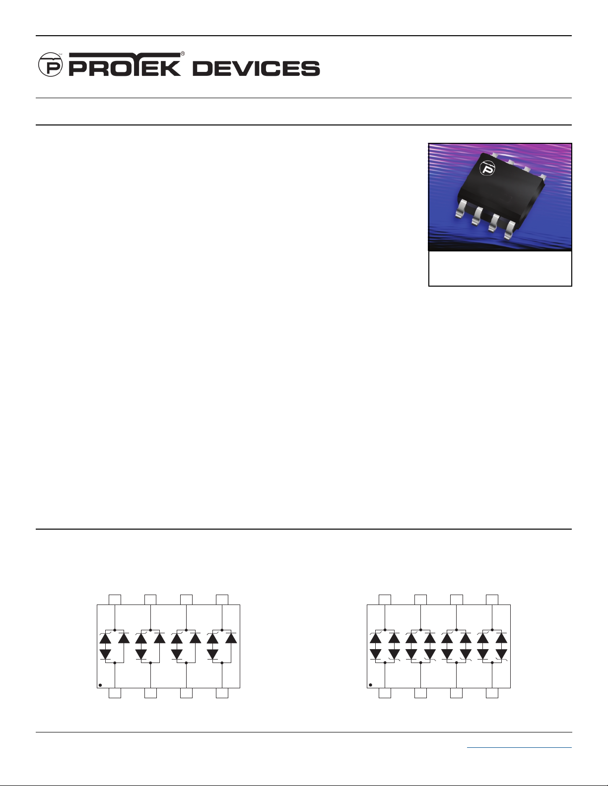
✔ Unidirectional & Bidirectional Configurations
✔ Available in Multiple Voltage Types Ranging From 3V to 24V
✔ Protects Up to Four (4) Lines
✔ ESD Protection > 40 kilovolts
✔ ✔
✔
LOW CAPACITANCE: 15pF
✔ ✔
thru
SMDA24LCC
SO-8
MECHANICAL CHARACTERISTICS
✔ Molded JEDEC SO-8 Package
✔ Weight 15 milligrams (Approximate)
✔ Flammability rating UL 94V-0
✔ 12mm Tape and Reel Per EIA Standard 481
✔ Marking: Logo, Marking Code, Date Code & Pin One Defined By Dot on Top of Package
PIN CONFIGURATIONS
UNIDIRECTIONAL BIDIRECTIONAL
8
1
7
2
6
3
5
4
8
1
7
2
6
3
5
4
105074.R5 8/03 www.protekdevices.com
Page 2
DEVICE CHARACTERISTICS
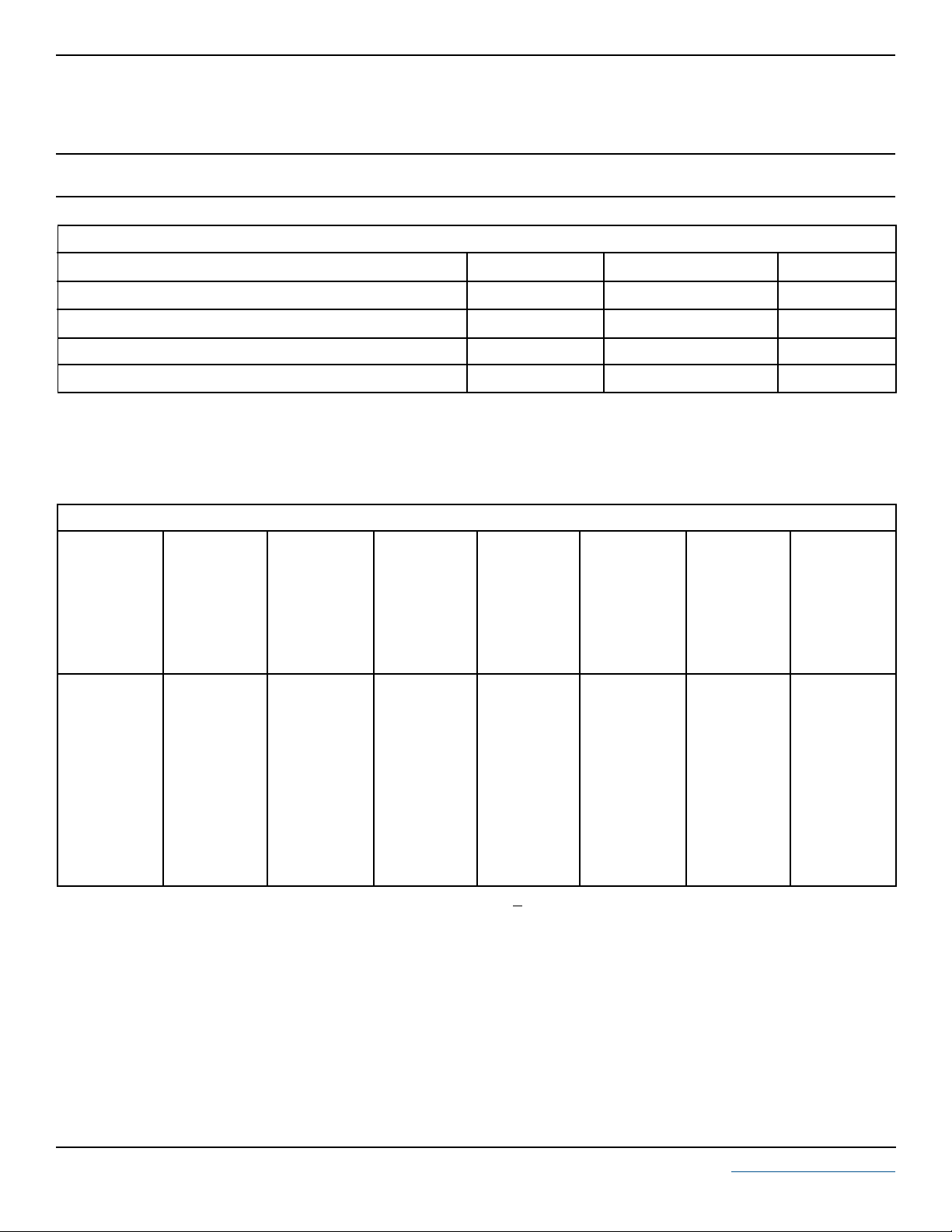
MAXIMUM RATINGS @ 25°C Unless Otherwise Specified
SMDA03LC
thru
SMDA24LCC
PARAMETER
Peak Pulse Power (tp = 8/20µs) - See Figure 1
Operating Temperature
Storage Temperature
Forward Voltage @ 50mA, 300µs - Square Wave (Note 1) Volts1.5V
Note 1: Only applies to unidirectional devices.
SYMBOL VALUE
P
PP
T
J
T
STG
F
500 Watts
-55°C to 150°C
-55°C to 150°C
ELECTRICAL CHARACTERISTICS PER LINE @ 25°C Unless Otherwise Specified
PA RT
NUMBER
(See Note 1)
SMDA03LC
SMDA03LCC
SMDA05LC
SMDA05LCC
SMDA08LC
SMDA08LCC
SMDA12LC
SMDA12LCC
SMDA15LC
SMDA15LCC
SMDA24LC
SMDA24LCC
DEVICE
MARKING
SLA
SLB
SLC
SLD
SLE
SLF
SLG
SLH
SLJ
SLK
SLL
SLM
RATED
STAND-OFF
VOLTAGE
V
WM
VOLTS
3.3
3.3
5.0
5.0
8.0
8.0
12.0
12.0
15.0
15.0
24.0
24.0
MINIMUM
BREAKDOWN
VOLTAGE
@ 1mA
V
(BR)
VOLTS
4.5
4.5
6.0
6.0
8.5
8.5
13.3
13.3
16.7
16.7
26.7
26.7
MAXIMUM
CLAMPING
VOLTAGE
(See Fig. 2)
@ IP = 1A
V
C
VOLTS
7.0
7.0
9.8
9.8
13.4
13.4
19.0
19.0
24.0
24.0
43.0
43.0
MAXIMUM
CLAMPING
VOLTAGE
(See Fig. 2)
@8/20µs
VC @ I
PP
10.9V @ 43.0A
10.9V @ 43.0A
13.5V @ 42.0A
13.5V @42.0A
16.9V @ 34.0A
16.9V @ 34.0A
25.9V @ 27.0A
25.9V @ 27.0A
30.0V @ 17.0A
30.0V @ 17.0A
49.0V @ 12.0A
49.0V @ 12.0A
MAXIMUM
LEAKAGE
CURRENT
@V
I
D
µA
125
125
20
20
10
10
1
1
1
1
1
1
WM
UNITS
°C
°C
MAXIMUM
CAPACITANCE
0V @ 1 MHz
C
pF
15
15
15
15
15
15
15
15
15
15
15
15
Note 1: Part numbers with a “C” suffix are bidirectional devices, i.e., SMDA03LCC.
2 www.protekdevices.com05074.R5 8/03
Page 3

GRAPHS
SMDA03LC
thru
SMDA24LCC
10,000
1,000
100
- Peak Pulse Power - Watts
PP
P
10
0.1 1 10 100 1,000 10,000
FIGURE 2
120
PP
100
80
60
40
- Peak Pulse Current - % of I
20
PP
I
0
0 5 10 15 20 25 30
PULSE WAVE FORM
t
f
Peak Value I
-t
e
td = t
t - Time - µs
PP
IPP/2
TEST
WAVEFORM
PARAMETERS
tf = 8µs
td = 20µs
PEAK PULSE POWER VS PULSE TIME
FIGURE 1
500W 8/20µs Waveform
td - Pulse Duration - µs
POWER DERATING CURVE
FIGURE 3
100
80
60
40
% Of Rated Power
20
0
0 25 50 75 100 125 150
- Lead Temperature - °C
T
L
Peak Pulse Power
8/20µs
Average Power
OVERSHOOT & CLAMPING VOLTAGE FOR SMDA05LC
FIGURE 4
20
10
0
-10
5 Volts per Division
-20
ESD Test Pulse: 5 kilovolt, 1/30ns (waveform)
3 www.protekdevices.com05074.R5 8/03
Page 4

SMDA03LC
thru
SMDA24LCC
APPLICATION NOTE
The SMDAxxLC & SMDAxxLCC Series are TVS arrays designed to protect I/O or data lines from the damaging effects of ESD, EFT and other types
of surges. This product series provides both unidirectional and bidirectional protection, with a surge capability of 500 Watts PPP per line for an 8/20µs
waveform and ESD protection > 40kV.
UNIDIRECTIONAL COMMON-MODE CONFIGURATION(Figure 1)
The SMDAxxLC Series provides up to four (4) lines of protection in a common-mode
configuration as depicted in Figure 1.
Circuit connectivity is as follows:
✔ Line 1 is connected to Pin 5.
✔ Line 2 is connected to Pin 6.
✔ Line 3 is connected to Pin 7.
✔ Line 4 is connected to Pin 8.
✔ Pins 1-4 are connected to ground.
BIDIRECTIONAL COMMON-MODE CONFIGURATION (Figure 2)
Ideal for Ethernet applications, SMDAxxLCC Series provides up to four (4) lines of
protection in a common-mode configuration as depicted in Figure 2.
Circuit connectivity is as follows:
✔ TPIN is connected to Pin 5.
✔ TPIP is connected to Pin 6.
✔ TPON is connected to Pin 1.
✔ TPOP is connected to Pin 2.
✔ Pins 3, 4, 7 & 8 are connected to ground.
CIRCUIT BOARD LAYOUT RECOMMENDATIONS
Circuit board layout is critical for Electromagnetic
Compatibility (EMC) protection. The following
guidelines are recommended:
✔ The protection device should be placed near the
input terminals or connectors, the device will
divert the transient current immediately before it
can be coupled into the nearby traces.
Figure 1. Unidirectional Common-Mode Protection
LINE 1
LINE 2
LINE 3
LINE 4
8
1
7
2
6
3
GND PLANE
Figure 2. Bidirectional Common-Mode Protection
TPIN
5
4
✔ The path length between the TVS device and the
protected line should be minimized.
✔ All conductive loops including power and ground
loops should be minimized.
✔ The transient current return path to ground
should be kept as short as possible to reduce
parasitic inductance.
✔ Ground planes should be used whenever
possible. For multilayer PCBs, use ground vias.
TPIP
8
ETHERNET REPEATER
12
TPON
TPOP
4 www.protekdevices.com05074.R5 8/03
7
6
34
5
Page 5

PACKAGE OUTLINE & DIMENSIONS
SMDA03LC
thru
SMDA24LCC
8
G
-T-
0.010” (0.25 MM)
8 PL
PACKAGE OUTLINE
-A-
5
M
P
0.010” (0.25 MM)
4 PL
-B-
1
4
M
B
PACKAGE DIMENSIONS
MILLIMETERS
SO-8
INCHES
DIM MIN MAX MIN MAX
D
C
K
S
S
M
T
B
A
MOUNTING PAD
0.050” ± 0.005”
A
B
R X 45º
C
D
0º - 10º
F
G
J
F
J
K
P
R
NOTES
1. - T - = Seating Plane and Datum Surface.
0.030” ± 0.005”
2. Dimensions “A” and “B” are Datum.
3. Dimensions “A” and “B” do not include mold protrusion.
4. Maximum mold protrusion is 0.015” (0.380 mm) per side.
5. Dimensioning and tolerances per ANSI Y14.5M, 1982.
6. Dimensions are exclusive of mold flash and metal burrs.
4.80
3.80
1.35
0.35
0.40
1.27 BSC
0.18
0.10
5.80
0.25
5.00
4.00
1.75
0.49
1.250
1.27 BSC
0.25
0.25
6.20
0.50
0.189
0.150
0.054
0.014
0.016
0.05 BSC
0.007
0.004
0.229
0.010
0.196
0.157
0.068
0.019
0.049
0.05 BSC
0.009
0.008
0.244
0.019
0.160” ± 0.005”
0.045” ± 0.005”
COPYRIGHT © ProTek Devices 2003
SPECIFICATIONS: ProTek reserves the right to change the electrical and or mechanical
characteristics described herein without notice (except JEDEC).
DESIGN CHANGES: ProTek reser ves the right to discontinue product lines without notice, and that
the final judgement concerning selection and specifications is the buyer’s and that in furnishing
engineering and technical assistance, ProTek assumes no responsibility with respect to the
selection or specifications of such products.
0.245” MIN
TAPE & REEL/BULK ORDERING NOMENCLATURE
1. Surface mount product is taped and reeled in accordance
with EIA-481.
2. Suffix-T7 = 7 Inch Reel - 1,000 pieces per 12mm tape,
i.e.,
SMDA05LC-T7.
3. Suffix-T13 = 13 Inch Reel - 2,500 pieces per 12mm tape,
i.e.,
SMDA05LC-T13.
4. No Suffix = Product Shipped in Tubes of 98 pcs per Tube.
Outline & Dimensions: Rev 1 - 11/01, 06009
ProTek Devices
2929 South Fair Lane, Tempe, AZ 85282
Tel: 602-431-8101 Fax: 602-431-2288
E-Mail: [email protected]
Web Site: www.protekdevices.com
5 www.protekdevices.com05074.R5 8/03
 Loading...