

Page 1
Mechanical
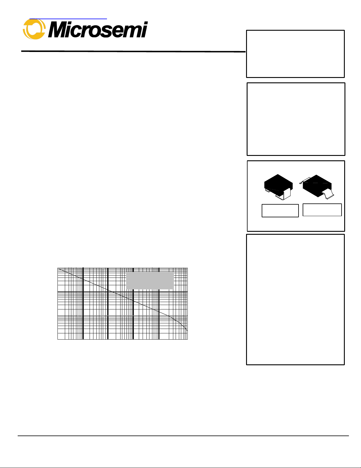
tp Pulse Time
P
PP
Peak Pulse Power
kW
(Wave Form - See
Non- Repetitive
查询SMCG/J6072A供应商
8700 E. Thomas Road
Scotsdale, AZ 85252
Phone: (480) 941-6300
Fax: (480) 947-1503
FEATURES:
• BIDIRECTIONAL
• 1500 WATTS PEAK POWER
• VOLTAGE RANGE FROM 5.5V TO 185V
• LOW INDUCTANCE
• LOW PROFILE PACKAGE FOR SURFACE MOUNTING
DESCRIPTION:DESCRIPTION:
These Transient Voltage Suppressor devices are a series of Bi-directional Silicon
Transient Suppressors used in AC applications where large voltage transients can
permanently damage voltage-sensitive components.
These devices are manufactured using two silicon PN, junctions in a back to back
configuration. They are characterized by their high surge capability, fast response
time, and low impedance, (R
The SMC series, rated for 1500 watts during a one millisecond pulse, can be used to
protect sensitive circuits against transients induced by lighting and inductive load
switching. The response time of TAZ clamping action is less than (5x10
therefore, they can protect Integrated Circuits, MOS devices, Hybrids, and other
voltage-sensitive semiconductors and components. This series of devices has also
been proven very effective as EMP and ESD suppressors.
) for clamping surge.
on
-9
) sec;
SMCG/J6036
thru
SMCG/J6072A
5.5 thru 185 Volts
1500 Watts
Transient Voltage
Suppressors
MAXIMUM RATINGS:MAXIMUM RATINGS:
1500 watts of peak pulse power dissipation at 25°°C
t
clamping
Operating and Storage Temperature: -65°° to +150°°C
Steady state power dissipation: 5.0 watts at T
Repetition rate (duty cycle): .01%
-
(0 volts to V
100
10
1.0
0.1
100ns
min): less than 5 x 10⁻⁹ seconds
(BR)
= 25°°C, at mounting plane.
L
1µs
Peak Pulse Power vs Pulse Time
10µs
Figure 1
100µs 1ms
Figure 2)
10ms
DO-214AB
DO-215AB
Characteristics
CASE: Molded, Surface
Mountable.
TERMINALS: Gull-wing or C-Bend
(modified J-bend) leads, tin lead
plated
POLARITY: No markings on
bi-directional devices.
PACKAGING: 16mm tape (See EIA
Std. RS-481.)
THERMAL RESISTANCE: 20°°C/W
(typical) junction to lead (tab) at
mounting plane.
MSC1364.PDF 01/06/00
Page 2
ELECTRICAL CHARACTERISTICS ELECTRICAL CHARACTERISTICS @ 25°c
Rated
BREAKDOWN
MAXIMUM
MAXIMUM
PEAK
Maximum
MICROSEMI
MICROSEMI
SMCG/J6036
thru
SMCG/J6072A
PART
NUMBER
MODIFIED
"G"
BEND LEAD
SMCG6036
SMCG6036A
SMCG6037
SMCG6037A
SMCG6038
SMCG6038A
SMCG6039
SMCG6039A
SMCG6040
SMCG6040A
SMCG6041
SMCG6041A
SMCG6042
SMCG6042A
SMCG6043
SMCG6043A
SMCG6044
SMCG6044A
SMCG6045
SMCG6045A
SMCG6046
SMCG6046A
SMCG6047
SMCG6047A
SMCG6048
SMCG6048A
SMCG6049
SMCG6049A
SMCG6050
SMCG6050A
SMCG6051
SMCG6051A
SMCG6052
SMCG6052A
SMCG6053
SMCG6053A
SMCG6054
SMCG6054A
SMCG6055
SMCG6055A
SMCG6056
SMCG6056A
SMCG6057
SMCG6057A
PART
NUMBER
MODIFIED
"J"
BEND LEAD
SMCJ6036
SMCJ6036A
SMCJ6037
SMCJ6037A
SMCJ6038
SMCJ6038A
SMCJ6039
SMCJ6039A
SMCJ6040
SMCJ6040A
SMCJ6041
SMCJ6041A
SMCJ6042
SMCJ6042A
SMCJ6043
SMCJ6043A
SMCJ6044
SMCJ6044A
SMCJ6045
SMCJ6045A
SMCJ6046
SMCJ6046A
SMCJ6047
SMCJ6047A
SMCJ6048
SMCJ6048A
SMCJ6049
SMCJ6049A
SMCJ6050
SMCJ6050A
SMCJ6051
SMCJ6051A
SMCJ6052
SMCJ6052A
SMCJ6053
SMCJ6053A
SMCJ6054
SMCJ6054A
SMCJ6055
SMCJ6055A
SMCJ6056
SMCJ6056A
SMCJ6057
SMCJ6057A
Stand-Off
Voltage
V
RM
(See Note 1)
VOLTS MIN MAX mA
5.5 6.75 8.25
6.0 7.13 7.88
6.5 7.38 9.02
7.0 7.79 8.61
7.0 8.19 10.00
7.5 8.65 9.55
8.0 9.0 11.0
8.5 9.5 10.5
8.5 9.9 12.1
9.0 10.5 11.6
9.0 10.8 13.2
10.0 11.4 12.6
10.0 11.7 14.3
11.0 12.4 13.7
11.0 13.5 16.5
12.0 14.3 15.8
12.0 14.4 17.5
13.0 15.2 16.8
14.0 16.2 19.8
15.0 17.1 18.9
16.0 18.0 22.0
17.0 19.0 21.0
17.0 19.8 24.2
18.0 20.9 23.1
19.0 21.6 26.4
20.0 22.8 25.2
21.0 24.3 29.7
22.0 25.7 28.4
24.0 27.0 33.0
25.0 28.5 31.5
26.0 29.7 36.3
28.0 31.4 34.7
29.0 32.4 39.6
30.0 34.2 37.8
31.0 35.1 42.9
33.0 37.1 41.0
34.0 38.7 47.3
36.0 40.9 45.2
38.0 42.3 51.7
40.0 44.7 49.4
41.0 45.9 56.1
43.0 48.5 53.6
45.0 50.4 61.6
47.0 53.2 58.8
VOLTAGE
V
@ I
(BR)
VOLTS
T
10
10
10
10
10
10
1
1
1
1
1
1
1
1
1
1
1
1
1
1
1
1
1
1
1
1
1
1
1
1
1
1
1
1
1
1
1
1
1
1
1
1
1
1
CLAMPING
VOLTAGE
VC @ I
(1 mSEC)
VOLTS
11.7 1000 128 .061
11.3 1000 132 .061
12.5 500 120 .065
12.1 500 124 .065
13.8 200 109 .068
13.4 200 112 .068
15.0 50 100 .073
14.5 50 103 .073
16.2 10 93 .075
15.6 10 96 .075
17.3 5 87 .078
16.7 5 90 .078
19.0 5 79 .081
18.2 5 82 .081
22.0 5 68 .084
21.2 5 71 .084
23.5 5 64 .086
22.5 5 67 .068
26.5 5 56.5 .088
25.2 5 59.5 .088
29.1 5 51.5 .090
27.7 5 54 .090
31.9 5 47 .092
30.6 5 49 .092
34.7 5 43 .094
33.2 5 45 .094
39.1 5 38.5 .095
37.5 5 40 .096
43.5 5 34.5 .097
41.4 5 36 .097
47.7 5 31.5 .098
45.7 5 33 .098
52.0 5 29 .099
49.9 5 30 .099
56.4 5 26.5 .100
53.9 5 28 .100
61.9 5 24 .101
59.3 5 25.3 .101
67.8 5 22.2 .101
64.8 5 23.2 .101
73.5 5 20.4 .102
70.1 5 21.4 .102
80.5 5 18.6 .103
77.0 5 19.5 .103
PP
STANDOFF
CURRENT
I
@ V
D
RM
µA
PULSE
CURRENT
(See Fig. 2)
I
PP
A %/°C
Temperature
Coefficient
α
V(BR)
MSC1364.PDF 01/06/00
Page 3

ELECTRICAL CHARACTERISTICS ELECTRICAL CHARACTERISTICS @ 25°C
SMCG/J6036
thru
SMCG/J6072A
MICROSEMI
PART
NUMBER
MODIFIED
"G"
BEND LEAD
SMCG6058
SMCG6058A
SMCG6059
SMCG6059A
SMCG6060
SMCG6060A
SMCG6061
SMCG6061A
SMCG6062
SMCG6062A
SMCG6063
SMCG6063A
SMCG6064
SMCG6064A
SMCG6065
SMCG6065A
SMCG6066
SMCG6066A
SMCG6067
SMCG6067A
SMCG6068
SMCG6068A
SMCG6069
SMCG6069A
SMCG6070
SMCG6070A
SMCG6071
SMCG6071A
SMCG6072
SMCG6072A
MICROSEMI
PART
NUMBER
MODIFIED
"J"
BEND LEAD
SMCJ6058
SMCJ6058A
SMCJ6059
SMCJ6059A
SMCJ6060
SMCJ6060A
SMCJ6061
SMCJ6061A
SMCJ6062
SMCJ6062A
SMCJ6063
SMCJ6063A
SMCJ6064
SMCJ6064A
SMCJ6065
SMCJ6065A
SMCJ6066
SMCJ6066A
SMCJ6067
SMCJ6067A
SMCJ6068
SMCJ6068A
SMCJ6069
SMCJ6069A
SMCJ6070
SMCJ6070A
SMCJ6071
SMCJ6071A
SMCJ6072
SMCJ6072A
Rated
Stand-Off
Voltage
V
RM
(See Note 1)
VOLTS MIN MAX mA
48.0 55.8 68.2
53.0 58.9 65.1
55.0 61.2 74.8
58.0 64.6 71.4
60.0 67.5 82.5
64.0 71.3 78.8
66.0 73.8 90.2
70.0 77.9 86.1
73.0 81.9 100.0
75.0 86.5 95.5
81.0 90.0 110.0
82.0 95.0 105.0
90.0 99.0 121.0
94.0 105.0 116.0
95.0 108.0 132.0
100.0 114.0 126.0
105.0 117.0 143.0
110.0 124.0 137.0
121.0 135.0 165.0
128.0 143.0 158.0
137.0 153.0 187.0
145.0 162.0 179.0
145.0 162.0 198.0
150.0 171.0 189.0
155.0 171.0 210.0
160.0 181.0 200.0
165.0 180.0 220.0
170.0 190.0 210.0
175.0 198.0 242.0
185.0 209.0 231.0
BREAKDOWN
VOLTAGE
V
@ I
(BR)
VOLTS
T
MAXIMUM
CLAMPING
VOLTAGE
VC @ I
PP
(1 mSEC
VOLTS
1
1
1
1
1
1
1
1
1
1
1
1
1
1
1
1
1
1
1
1
1
1
1
1
1
1
1
1
1
1
89.0 5 16.9 .104
85.0 5 17.7 .104
98.0 5 15.3 .104
92.0 5 16.3 .104
108.0 5 13.9 .105
103.0 5 14.6 .105
118.0 5 12.7 .105
113.0 5 13.3 .105
131.0 5 11.4 .106
125.0 5 12.0 .106
144.0 5 10.4 .106
137.0 5 11.0 .106
158.0 5 9.5 .107
152.0 5 9.9 .107
176.0 5 8.5 .107
168.0 5 8.9 .107
191.0 5 7.8 .107
182.0 5 8.2 .107
223.0 5 6.7 .108
213.0 5 7.0 .108
258.0 5 5.8 .108
245.0 5 6.1 .108
274.0 5 5.5 .108
261.0 5 5.7 .108
292.0 5 5.1 .108
278.0 5 5.4 .108
308.0 5 4.9 .108
294.0 5 5.1 .108
344.0 5 4.3 .108
328.0 5 4.6 .108
MAXIMUM
STANDOFF
CURRENT
I
@ V
D
RM
µA
PEAK
PULSE
CURRENT
(See Fig. 2)
I
PP
Maximum
Temperature
Coefficient
α
V(BR)
A
%/°C
Microsemi Corp.'s SMC Series (1500W) surface mountable packages are designed specifically for transient voltage suppression. The wide
leads assure a large surface contact and low resistance path for surge current flow to ground. These high-speed transient voltage
suppressors can be used to effectively protect sensitive components such as integrated circuits and MOS devices.
Note 1: A TAZ is normally selected according to the rated "Stand Off Voltage" V
which should be equal to or greater than the DC or continuous
RM
peak operating voltage level.
MSC1364.PDF 01/06/00
Page 4

TRANSIENT VOLTAGE SUPPRESSORSTRANSIENT VOLTAGE SUPPRESSORS
t - Time - msec
I
PP
Peak Pulse Current - % I
PP
VR = Rated
t
100
50
0
r
Peak Value I
Half Value I
Test Wave Form
PP
t
10 X 1000 Wave Form
PP
as Defined by R.E.A
1
Figure 2
Pulse Waveform
Parameters
tr = 10 µsec
= 1000 µsec
p
2
SMCG/J6036
thru
SMCG/J6072A
100%
)
PP
75
) or Current (I
50
PP
25
0
In Percent of 25ºC Rating
3
Peak Pulse Power (P
0
50
T - Temperature - º C
100
FIGURE 3
Derating Curve
150
200
10000
5000
2000
1000
500
200
100
50
20
10
VR = 0
Stand-Off Voltage
5.0 10 20 50 100 200
V
Breakdown Voltage - Volts
BR
Figure 4
TYPICAL CAPACITANCE
VS BREAKDOWN VOLTAGE
MSC1364.PDF 01/06/00
 Loading...