

Page 1
DS19002 Rev. 11 - 2 1 of 3 SMBJ5.0(C)A - SMBJ170(C)A
SMBJ5.0(C)A - SMBJ170(C)A
600W SURFACE MOUNT TRANSIENT VOLTAGE
SUPPRESSOR
Maximum Ratings
@ TA= 25°C unless otherwise specified
Characteristic Symbol Value Unit
Peak Pulse Power Dissipation
(Non repetitive current pulse derated above T
A
=25°C)
(Note 1)
P
PK
600 W
Peak Forward Surge Current, 8.3ms Single Half Sine
Wave Superimposed on Rated Load (JEDEC Method)
(Notes 1, 2, & 3)
I
FSM
100 A
Instantaneous Forward Voltage @IPP= 35A VBR<100V
(Notes 1, 2, & 3) V
BR
³100V
V
F
3.5
5.0
V
V
Operating and Storage Temperature Range
T
j,TSTG
-55 to +150 °C
Features
·
Case: SMB, Transfer Molded Epoxy
·
Terminals: Solderable per MIL-STD-202,
Method 208
·
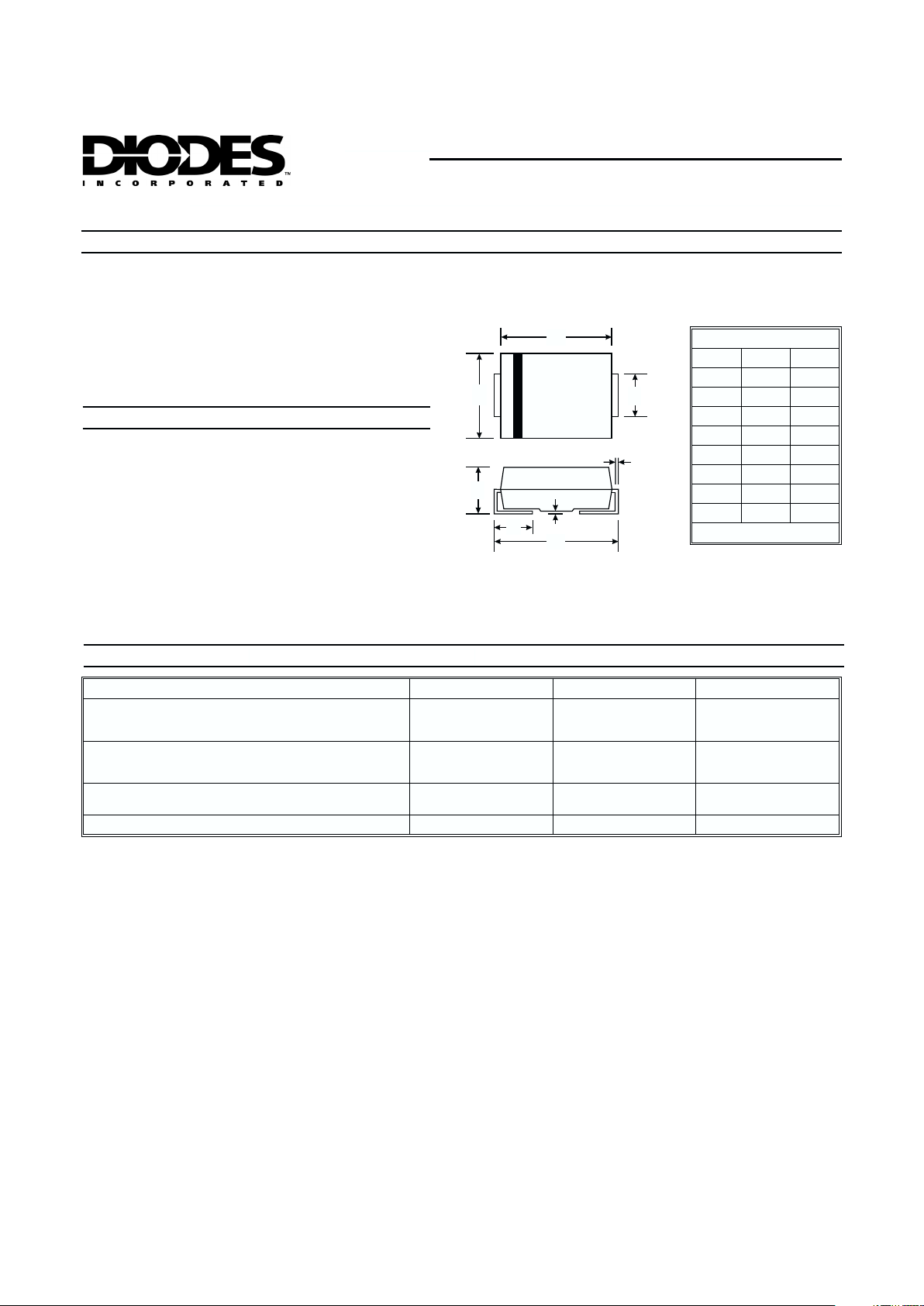
Polarity Indicator: Cathode Band
(Note: Bi-directional devices have no polarity
indicator.)
·
Marking: Date Code and Marking Code
See Page 3
· Weight: 0.1 grams (approx.)
· Ordering Info: See Page 3
·
600W Peak Pulse Power Dissipation
·
5.0V - 170V Standoff Voltages
·
Glass Passivated Die Construction
·
Uni- and Bi-Directional Versions Available
·
Excellent Clamping Capability
·
Fast Response Time
·
Plastic Material - UL Flammability
Classification Rating 94V-0
Mechanical Data
SMB
Dim Min Max
A 3.30 3.94
B 4.06 4.70
C 1.91 2.21
D 0.15 0.31
E 5.00 5.59
G 0.10 0.20
H 0.76 1.52
J 2.00 2.62
All Dimensions in mm
A
B
C
D
G
H
E
J
Notes: 1. Valid provided that terminals are kept at ambient temperature.
2. Measured with 8.3ms single half sine-wave. Duty cycle = 4 pulses per minute maximum.
3. Unidirectional units only.
Page 2

DS19002 Rev. 11 - 2 2 of 3 SMBJ5.0(C)A - SMBJ170(C)A
Part Number
Add C For
Bi-Directional
(Note 4)
Reverse
Standoff
Voltage
Breakdown
Voltage
V
BR
@ IT(Note 5)
Test
Current
Max. Reverse
Leakage @
V
RWM
(Note 6)
Max. Clamping
Voltage @ I
pp
Max. Peak Pulse
Current
Ipp
Marking Code
V
RWM
(V)
Min (V) Max (V)
IT(mA)
I
R
(mA)
V
C
(V)
(A) BI- UNI-
SMBJ5.0(C)A
5.0 6.40 7.23 10 800 9.2 65.2 AE KE
SMBJ6.0(C)A
6.0 6.67 7.67 10 800 10.3 58.3 AG KG
SMBJ6.5(C)A
6.5 7.22 8.30 10 500 11.2 53.6 AK KK
SMBJ7.0(C)A
7.0 7.78 8.95 10 200 12.0 50.0 AM KM
SMBJ7.5(C)A
7.5 8.33 9.58 1.0 100 12.9 46.5 AP KP
SMBJ8.0(C)A
8.0 8.89 10.23 1.0 50 13.6 44.1 AR KR
SMBJ8.5(C)A
8.5 9.44 10.82 1.0 10 14.4 41.7 AT KT
SMBJ9.0(C)A
9.0 10.00 11.50 1.0 5.0 15.4 39.0 AV KV
SMBJ10(C)A
10.0 11.10 12.80 1.0 5.0 17.0 35.3 AX KX
SMBJ11(C)A
11.0 12.20 14.40 1.0 5.0 18.2 33.0 AZ KZ
SMBJ12(C)A
12.0 13.30 15.30 1.0 5.0 19.9 30.2 BE LE
SMBJ13(C)A
13.0 14.40 16.50 1.0 5.0 21.5 27.9 BG LG
SMBJ14(C)A
14.0 15.60 17.90 1.0 5.0 23.2 25.8 BK LK
SMBJ15(C)A
15.0 16.70 19.20 1.0 5.0 24.4 24.0 BM LM
SMBJ16(C)A
16.0 17.80 20.50 1.0 5.0 26.0 23.1 BP LP
SMBJ17(C)A
17.0 18.90 21.70 1.0 5.0 27.6 21.7 BR LR
SMBJ18(C)A
18.0 20.00 23.30 1.0 5.0 29.2 20.5 BT LT
SMBJ20(C)A
20.0 22.20 25.50 1.0 5.0 32.4 18.5 BV LV
SMBJ22(C)A
22.0 24.40 28.00 1.0 5.0 35.5 16.9 BX LX
SMBJ24(C)A
24.0 26.70 30.70 1.0 5.0 38.9 15.4 BZ LZ
SMBJ26(C)A
26.0 28.90 33.20 1.0 5.0 42.1 14.2 CE ME
SMBJ28(C)A
28.0 31.10 35.80 1.0 5.0 45.4 13.2 CG MG
SMBJ30(C)A
30.0 33.30 38.30 1.0 5.0 48.4 12.4 CK MK
SMBJ33(C)A
33.0 36.70 42.20 1.0 5.0 53.3 11.3 CM MM
SMBJ36(C)A
36.0 40.00 46.00 1.0 5.0 58.1 10.3 CP MP
SMBJ40(C)A
40.0 44.40 51.10 1.0 5.0 64.5 9.3 CR MR
SMBJ43(C)A
43.0 47.80 54.90 1.0 5.0 69.4 8.6 CT MT
SMBJ45(C)A
45.0 50.00 57.50 1.0 5.0 72.7 8.3 CV MV
SMBJ48(C)A
48.0 53.30 61.30 1.0 5.0 77.4 7.7 CX MX
SMBJ51(C)A
51.0 56.70 65.20 1.0 5.0 82.4 7.3 CZ MZ
SMBJ54(C)A
54.0 60.00 69.00 1.0 5.0 87.1 6.9 DE NE
SMBJ58(C)A
58.0 64.40 74.60 1.0 5.0 93.6 6.4 DG NG
SMBJ60(C)A
60.0 66.70 76.70 1.0 5.0 96.8 6.2 DK NK
SMBJ64(C)A
64.0 71.10 81.80 1.0 5.0 103.0 5.8 DM NM
SMBJ70(C)A
70.0 77.80 89.50 1.0 5.0 113.0 5.3 DP NP
SMBJ75(C)A
75.0 83.30 95.80 1.0 5.0 121.0 4.9 DR NR
SMBJ78(C)A
78.0 86.70 99.70 1.0 5.0 126.0 4.7 DT NT
SMBJ85(C)A
85.0 94.40 108.20 1.0 5.0 137.0 4.4 DV NV
SMBJ90(C)A
90.0 100.0 115.50 1.0 5.0 146.0 4.1 DX NX
SMBJ100(C)A
100.0 111.0 128.00 1.0 5.0 162.0 3.7 DZ NZ
SMBJ110(C)A
110.0 122.0 140.00 1.0 5.0 177.0 3.4 EE PE
SMBJ120(C)A
120.0 133.0 153.00 1.0 5.0 193.0 3.1 EG PG
SMBJ130(C)A
130.0 144.0 165.50 1.0 5.0 209.0 2.9 EK PK
SMBJ150(C)A
150.0 167.0 192.50 1.0 5.0 243.0 2.5 EM PM
SMBJ160(C)A
160.0 178.0 205.00 1.0 5.0 259.0 2.3 EP PP
SMBJ170(C)A
170.0 189.0 217.50 1.0 5.0 275.0 2.2 ER PR
Notes: 4. Suffix C denotes Bi-directional device.
5. V
BR
measured with ITcurrent pulse = 300ms
6. For Bi-Directional devices havingV
RWM
of 10V and under, the IRis doubled.
Page 3

DS19002 Rev. 11 - 2 3 of 3 SMBJ5.0(C)A - SMBJ170(C)A
1 10 100 1000
10
100
1000
10,000
V , REVERSE STANDOFF VOLTAGE (V)
Fi
g
.2 Typical Junction Capacitance
RWM
C , CAPACITANCE (pF)
j
T=25C
f = 1.0 MHz
j
°
V = 50 mV p-p
sig
Measured at
zero bias
Uni-directional
Bi-directional
10 X 1000 Waveform
as defined by REA
0 25 50 75 100 125 150 175 200
100
75
50
25
0
T , AMBIENT TEMPERATURE ( C)
Fi
g
. 1 Pulse DeratingCurve
A
°
PEAK PULSE DERATINGIN%OF
PEAK POWER OR CURRENT
XX = Product type marking code (See Page 2)
= Manufacturers’ code marking
YWW = Date code marking
Y = Last digit of year ex: 2 for 2002
WW=Weekcode01to52
YWW
XX
Marking Information
Notes: 4. For Packaging Details, go to our website at http://www.diodes.com/datasheets/ap02007.pdf.
Device
Packaging Shipping
SMBJXXX(C)A-13
SMB 5000/Tape & Reel
Ordering Information
(Note 4)
0.1 1.0
t PULSE WIDTH ( s)
Fi
g
. 3 Pulse RatingCurve
p
m
0.1
10 100
1.0
10
1000 10000
T=25Cj°
P , PEAK PULSE POWER (kW)
d
100
Non Repetitive
Pulse Waveform
Shown in Fig. 4
012
3
100
50
0
I , PEAK PULSE CURRENT (%I )
Ppp
t = 10 srm
Peak Value I
pp
Half Value I /2
pp
10 X 1000 Waveform
as defined by R.E.A.
t
p
t, TIME (ms)
Fi
g
. 4 Pulse Waveform
 Loading...